Table of Contents
Advertisement
Quick Links
Advertisement
Table of Contents

Summary of Contents for ADENDORFF ZX6350G
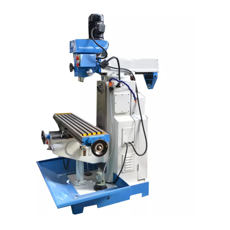
- Page 1 DRILLING/MILLING MACHINE OPERATION MANUAL...
- Page 2 A WARNING 1. Read and understand the entire instruction manual before operating machine. Always wear approved safety glasses/face shields while using this machine . Make certain the machine is properly grounded. 4. Before operating the machine, remove tie, rings watches, other jewel- ry, and roll up sleeves above the elbows.
- Page 3 plugged from the power source. 9. Use the right tool. Don't force a tool or attachment to do a job which ed for. it was not desi 10. Make certain the motor switch is in the OFF position before con- necting the machine to the power sipply.
-
Page 4: Inspection And Acceptance
1. Attention Inspection And Acceptance 1. 1 Please check carefully when open the package and make sure no parts are rmss1ng. 1. 2 Safety Please read the operation manual carefully before the installation and adjustment of the machine. When finish the installation, check all the de- tails and trial run the machine idlly before put it into operation. - Page 5 3. Opertion Instruction Before starting the machine , read carefally the operation manual 3. 1. 1 and be fully acquainted with all the details. The oprater should be familiar with all the rules and points of 3. 1. 2 attention of running and maintaining the machine. Remove all the anti - rust coating or grease from the machine.
-
Page 6: Use And Maintenance
I USAG The machine is used for cutting metals and nometals. It's suitable to drill, mill, and widely use in the field of instrument, machining repairing for cutting a single part or a batch of parts. II USE AND MAINTENANCE ( Ref er to chart 1. - Page 7 working table must be hoisted to the nearest position to the spindle when the 2 - blade milling tool is used. ° The spindle box that transmitted by the belt can be surivled at ( by gear °) , when operating, pls loose the retaining nut and pay atten ±...
-
Page 8: Operation
MANUAL OPERATION � MAIN PARA. M ETER ZX6350G � Max. drillin2 dia. C Iron) ..Max. end milling dia. 25 (Iron) Spindle taper Spindle speed number 115- 1750 (V) Spindle speed range (50/60Hz) 40-1300 (H) Distance bet een Vertical spindle... - Page 9 MAIN PARAM ZX6350(3PH) lttm ZX6350C(3PH) � 50 -I 15/l6 ( lron) Ma\ drilling dia 50 - 115/16" ( Iron) Ma\ horizontal milling width. 80 -3" 80-3 25 -1 " ( I ron ) Ma.\ ,ertical milling dia 25 - l" (I ron ) M.
- Page 10 V : THE SYSTEM O TRANSMITION CHANGED SPEED 1. Transmition of power The machine power is transmitted through gear on the shaft of motor and moving - gears to the gear of spindle . 2. Q) Vertical shaft : when change speed , first cut off power, then change the handle to the position ( you want ( Gear Head) .
- Page 11 VII ELECT C SYSTEM Electrical circuit abopt the advanced international component to make up , which make the machine easy to operate and safe. VIlI TRANSPORT AND ATT . E NTION While transporting machine must be cafeful to carry and put down. SIMPLE MALFUNCTION &...
- Page 13 - -' � l � 1520 No. 1 bearing position Rollin g � ·-VI � -,� - 1 2 -...
-
Page 14: Maintenance
Preventive Maintenance For securing the accuracy and life of the machine, we offer the follow ing maintencance charts. Frequency Item 1 . It is necessary t(? oil each lubrication point before operation. Daily 2. It is necessary to release the clamps , clean and lu- bricate the table after opertion. - Page 15 MAINTENANCE ( 1) Table saddle ways adjustment. Table a. Remove all dirt ( from area) ,..._ ___,�� b. Turn the table gib screw clockwise Adjusting while moving the table until slight drag is Screw Saddle felt ( 2) Saddle knee ways adjustment. a.
- Page 16 MAINTENANCE (3) Ram ways adjustment. '· a. Remove all dirt ( from area) b. Turn the ram gib screw clockwise ��==I Adi us ting screw while moving the ram until slight is felt - 15 -...
-
Page 17: Installation
Installation FOUNDATION PLAN Ideally this machine shoule he bolted to a concrete foundation , The machine should he placed on a solid level flo. or anti - vibration pads to prevent ang rocki movement . · r -·----- 1110 - \6-... - Page 18 Installation ZERO ZERO ... - , I<. ';_•: : : -=-".f== ==\_-' Adjust the level of the machine to make sure the allowrance is under 0. 0411000mm in the across and horizontal direction after fixing the ma chine on the base by four bolts. If necessary pads under the base. Trial Before trial tun.
- Page 21 1 1 1, fvi - � .s:v , \ 16 - i'f � � . CB - ? j • � , - t ( � � � � ' % �' t· pow er =, .J:l..._ - - - ,;-::9� fl -;; /� - .
- Page 22 C:Gear head � 2 9 �8 ""59 �63 ." , . q,_60 1> - 21 -...
- Page 23 , rizontal spindle D-Ho � - - 22 -...
- Page 24 E · G e a r b o x • �11 �\J ..10 � , <" � ,,I' � � � ' � 20 -� 54 � J Q) -, - -- - - <t3 - 23 -...
- Page 25 F : C h a n g i n g s p e e d p a r t � 2 1 - 24 -...
- Page 26 A: COLUMN PART NAME NAME QUTY QUTY BASE OIL CUP SCREW COLUMN SUPPORT( TEST) BOLT SCREW CONNECT TUBE WASHER HOLD BRACKET CONNECT TUBE SCREW WASHER T BOLT BOLT WASHER BOLT ELECTRIC PUMP COLLAR BOLT SCREW HOLE SUPPORT SUPPORT DUST COVER BOLT AROVND BRACKE SCREW...
- Page 27 NAME QU'I'Y NAME QUTY A61 BALL BEARING SHAFT COLLAR SCREW SCREW CONECAL GEAR CONICAL PIN WASHER COLLAR SCREW SHAFT COLLAR SCREW BALL BEARING SCALE RING SCREW COLLAR HANDLE LIFT BAR TOOL HOLDER CUl1ER BAR COll.AR SUPPORT BOLT COLLAR SCREW OIL CUP WASHER BEHIND COVER SCREW...
-
Page 28: Ball Bearing
B:TABLE NAME QUTY NAME QUTY HANDLE HANDLE COLLAR CLAMP BLOCK SCREW HAND BOARD WASHER HAND WHEEL BEVEL IRON SCREW ADJUST SCREW OIL COVER ffiE LEAD gJffiW" SCALE RING BALL BEARING BALL BEARING OIL CUP SCREW SUPPORT OIL CUP SCREW SUPPORT BALL BING SCALE RING WASHER... - Page 29 C:GEAR HEAD QUTY QUTY NAME NAME DRIVING SHAFT DRIVING SHAFT COLLAR OIL SEAL SCREW GEAR BALL BEARING GEAR SCREW GEAR 0-RING COLLAR RETAINING RING BEARING COLLAR GEAR BOX COVER RETAINING RING COLLAR SHAFT BEARING 431,CREW COLLAR DRIVING SHAFT BEARING GEAR RETAI NINGRING SCREW SCRE\V...
- Page 30 NAME QUTY SPRING SCREW OIL POSITION BOLT - 29 -...
- Page 31 HORIZONTAL SPINDLE NAME QUTY NAME QUTY SCREW BEARING COLLAR COVER SCREW SCREW COLLAR SPINDLE SCREW BEARING BEATING CRESCENT RING GEAR GEAR COLLAR GEAR GEAR CRESCENT RING BEARING GEAR COLLAR GEAR COLLAR GEAR CRESCENT RING SCREW DRIVING SHAFT COVER BEARING SCREW COLLAR COLLAR SCREW...
- Page 32 NAME QUTY COLLAR 0-RING SCREW BEARING COLLAR COVER SCREW PULLEY CRESCENT RING V -BELT PULLEY MOTOR WASHER MOTOR BASE BASE BOLT BOLT WASHER SHAIT -31-...
- Page 33 E:GEAR BOX QUTY QUTY NAME NAME SCALE RING SPINDLE DUST COVER HANDLE BRACKET COVER BEARING BOLT SLEEVE HANDLE BAR BEARING KNOB WASHER HANDLE SCREW HANDLE COLLAR SCREW SCALE SPRING PLATE RIVET SPRING CAP WORM GEAR SCREW BEARING SPRING SEAT }1ALL COVER �·...
- Page 34 F: CHANGE PEED PART QUTY QUTY NAME NAME COVER STEEL BALL SPRING HANDLE SCREW OIL POSITION SCREW COLLAR 0 -RING SHA IT SHAFT SHAFT CRESCENT RING LIFTFORK LIITFORK LIFTFORK COVER BOLT SCREW - 33 -...
- Page 36 List of electrical equiment Legend N aIDe & usage Technical Remark YD100L -8/4 3PH V spindte motor 0. 85/1 . 5kw vl YlOOl -4 3PH 2. 2KW 83 H. spindle motor X. axi s power feed YS6322 3PH 370W B5 motor Coolant pump AB -12 3PH 40W 121 / nun...
- Page 38 List of electrical equiment Name & usage Technical Remark Legend YDlOOL-8/4 3PH V. spindle motor 0. 85/L. 5 KW Vl H. spindle motor YIOOL-4 3PH 2. 2KW 83 X. axis power feed YS6322 3PH 370W 85 motor Coolant pump AB -12 3PH 40W 121/min DZS2 -20/330H le: IOA Circuit breaker 3PH 220V 50/60HZ...
- Page 41 • L. t f I t . I e ec r1ca equ1men IS. \l Legend Name & usagt Technical data Qt y Remark THREE -PHASE YDlOOL-8/4 INDUCTION MOTOR 3PH 0. 85/1. 5KW VI (VERTICAL) THREE -PHASE YIOOL -4 INDUCTION MOTOR 3PH 2.
- Page 42 Accuracy Testing List Allowance Measured Item Test lllustration error Value A Horizontal 0.04/1000 Flathnesss B Cross 0.04/1000 Work flatness 0.04/200 0.02 Run out of A. End spindle face B. 300mm to :spindle face 0.04 spindle bore Kick of spindle 0.02 The perpendicular between spindle A LongiLudinal 0.
-
Page 43: Packing List
.._..:. 1 ota\ -paie� \ PACKING LIST ZX6350G page 1 NAME MODEL QTY. MACHINE DRILL CHUCK q, 16 INNER HEXAGON SPANNER WEDGE SHIFTER REDUCTION SLEEVE DRAW BAR SPINDLE ARBOR S21-24 WRENCH MILL CHUCK VICE . MILUNG BAR BORING BAR OPERATION MANUAL QUALl1Y CERTIFICATE •. - Page 44 Dear Users: Thank yon for your purchase of the LOK SHUN CNC EQUIPMENT LTD.-SINO Digital Display Meter, of which the main purpose is provide detection and positioning f\mctions for machine tool processing. Before use, please read the following safety instructions and precautions for saf e, ty operation of the new digital display meter device.
- Page 46 lllnstratlon of Panel and K.iyboard Illustration of Panel and I{eyboard --- -------- - Key for cleaning the displayed Ca1>tion of the Keyboard of SDS6 value to zero ----------Keys for Axis selection ------------ Function key for gelling one half ·00000 ------------- Key for the conversion the ry ke ys for di gi t s 000 0 0 meter System/ British system...
- Page 47 fUustn1Uon of Pani;,I and l(eyboal'd Catnlogue �------------ Tool compensation function key; Catalogue In calculation function as tangent trigonometric function Fu11ctio11s ........... �.,H ....1 Key for the conversion of relative/absolute display B .. Smooth R ................15 @ @----------- (Be the same with: MIIL _ MS , MIIL _ M) Key for the selection of upper/Iowel' term or 11Iane �...
- Page 48 I, Tool Diameter Com p ensation ......, ... : ....74 ( Be the same with: 3V-MIIL _ MS ) 200 �fool Storeroon1 ............. 77 ( Be the same wit!,: LATHE ) K. The Function Of Measure For Taper ........81 (Be the same with: LATHE ) l:,.
- Page 49 We take pleasure to tell you that this machii1e tool optical digital display device you are using is the one most popular in Europe. You will be able to use this device easily after you have read this manuaL thoroughly. Thauk you! rev ers e dire ctio n cou nt.
- Page 51 A. Bask Fundlon A. Basic Funciion along the direction of arrow and let it come to touch the other edges wo, r king piece, then do the next step can determine the center position. IJ[E-· -] 7) Return to the absolute mode I]] �3l]] mDJ 1so.0001 f==f$��...
- Page 52 A. Basic MuncHon Not e: onl y the lath e ma chin e digi tal dis A, Baste Funcfion pla yer has tbe fun ctio n; tlie J>ar am eter f;i:'.'i"1? opt ion " wh etb er tlie \'\Z axi s sum min The distance of effective range of raster ruler g dis pla y"...
- Page 53 A. Daslc Function A, Basic Function 2, Press 12}---'), � to choose the 1st absolute zero of the raster ruler as the ! !,11]1 5 1 IZ/EIRI mechanical origin. ! IR/EISIEIT/ /)(I f.v.l uncertain value). 6) Input the compensation setup of the 1 '' segment I I I I 19)919151 0 I INIOI I I I 111 At this time, firstly move the I I I I 19)919151 [r]...
- Page 54 A, !Jaslc Function Finding the function of the mechanical origin · · last lime 2.First!y move the raste r ruler to the smallest val u e, and then set up 3) Key the new correction factor in: Segmented compensation. When inputting the quantity of compensation segments and the compensation length, do not make any .
- Page 55 D, Sn10oth R(lle the sa1ue with: l\IIll,J\fS � l\.fllL_h1) A, llasic Function 13. Sleep Switch (no tllis function fo1· the digital display box witi 3;· display) The switch 011 the back panel of the digital display box may once be turn off during the processing of a working piece.
- Page 56 , -B. Smooth R{Be the same with: 1\-fllL_�lS \ l\-fiJL_l\1) the plane coordinate and the start and end angles of a YZ the coordinate of a point is its position with respect . · . · .:.. ton the plane. The coordinale of zero point 0:(0, ...-::.r--1 The coordinate of PointA:(20,...
- Page 58 11, Smooth R ( Be the same with: 1\UJL _ l'\IS , i\llJL _ !\ 1) B-. Smooth R { Be the same with: .I\JlIL _ l\lS , �llIL J \ f) [/i[;il]Jilll[[J l/ifdiJJH TIU l 1rs.tpoin1. >:""'· ; _ : _ rxr:r r 1 :}:'£-"•...
- Page 60 ,� B. Smooth R(Be the �me with: :MIIL_MS ... �..,.. rt t) I , ISL(/JVJQ] 0 f'fiTT"T _=:. 7) Enter the diameter of the tool. Use a circular arc milling tool ��-�[ij Key�tEJ �'It Ii I ii%! Use a flat end milling tool 'OI®1ll 0 U[[J]UJJi] Key(£)-;.tEJ iTSD...
- Page 61 B. Smooth R(Be the some with: MllL_MS .. MllL""M) Use a flat end milling tool Ql.8:5.MQl 0 �!JOI . • I I I fr setting as Fig. ( a) �m �..C..C-W-C- Use a flat end milling tool I. · I ;Ji:l[Oj/J�O] 0 setting as Fig.
- Page 63 C. Simple R(Ge Ote snme with; lV-1\lllLJ\lS. 2V-1\l_ ! I_L = '-' ) ------ B. Smoo!b R(lJc- the same with: l\lllL_l\lS � �filL_i\l) 9) Enter the start angle of the arc. 121-(�j-,•{£)-EJ Key l!;J JO) Enter the end angle of the arc. lf.' JJ JJl+ITILI I 11) Detennine inner/outer circle mode.
- Page 64 C. Simple R{Ile lbe same with: 2V-l\111L l\1S, 2V�J\1JIL_l\1) C. Sintp1e R(De the sanie wilh: lV-i\1UL_I\lS-. 2V-i\111L_�I) 3. Select the processing plane, XY, XZ or YZ. (ARC-XY) (ARC-XZ) (ARC-YZ) 4. Enter the of the circular arc (RDDIUS) 5. Enter the diameter of the tool (TI., DLA): When processing the arc in Planes XZ and YZ, end mill is used and the processing in carried by the end edge tool so the diameter valve to be entered should be zero.(refer to step 5 m the ope;ation procedure of the smooth R function).
- Page 65 ��--=��-����- c. Sin1plc R(Be the SfUltC with: 2v-r.mL l\1S .. . 2V�l\IIIL l\f) l & f?[l:-1 i?JY[J Select the processing plane Key[§)or!]) G1JRl[]3iiJZf] �1 iR ICHYlZD 4) Select Plane XZ 0lRllI:1 Key{gj IB0]]1IlDISLJ 5) Enter the radius of the circular arc KeyiZ}--->...
- Page 66 C. S_lmple .R(Be the same with: 2V-l\JUL _I\JS .. 2\q\lilL _l' H ) C. Simple R(De: the same wllh: 2V-l\llIL_!\IS .. 2V-i\1llLJ.\1) *Take the proce ssing of an inner circul ar arc as exam ple: $?i';fet\!o the display, move the machine tool to bring the displayed valve on X i•xis into zero, then tum the Z axis star wheel to let the machine table rise or l) At first, align the tool to face just the start point( Point A or Point B)
Need help?
Do you have a question about the ZX6350G and is the answer not in the manual?
Questions and answers