Table of Contents
Advertisement
Quick Links
Instruction Manual
Cooling Water Treatment Controller
Fill in serial
number here
Supplied by:
Convergent Water Controls
2/4 Huntley Street, PO Box 7058
Alexandria NSW 2015
t: (02) 9698 3131
f: (02) 9698 3210
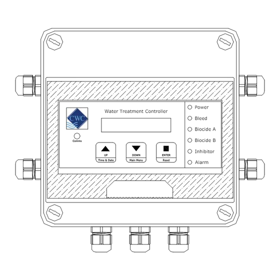
Model: DIGICHEM-XP2
Water Treatment Controller
Comms
UP
Time & Date
Main Menu
w: cwc.com.au
e: support@cwc.com.au
Power
Bleed
Biocide A
Biocide B
Inhibitor
DOWN
ENTER
Reset
Alarm
Pty Ltd
Refer to
back page
M1 ver 1.5
Advertisement
Table of Contents

Subscribe to Our Youtube Channel
Summary of Contents for CWC DIGICHEM-XP2
- Page 1 Instruction Manual Cooling Water Treatment Controller Model: DIGICHEM-XP2 Power Water Treatment Controller Bleed Biocide A Biocide B Comms Inhibitor DOWN ENTER Time & Date Main Menu Reset Alarm Fill in serial Refer to number here back page Supplied by: Convergent Water Controls...
- Page 2 Manufacturer: Convergent Water Controls Pty Ltd, Sydney Australia. Note: On-going product development at Convergent Water Controls may lead to changes in the specifications of this product. Warranty: This product is guaranteed for a period of 12 months from installation date or 18 months from Invoice date (whichever occurs first). The warranty applies to manufacturing or component defects which may cause the unit to malfunction under specified conditions.
-
Page 3: Table Of Contents
Introduction........................... 7 Installation ..........................7 2.1 Electrical Wiring ........................... 7 2.2 Conductivity Probe Installation & Maintenance................8 Controller Functionality ......................9 3.1 Menu Logic..........................9 3.2 Pushbuttons ..........................10 3.3 LED Indication ........................... 11 3.4 Comms Port..........................12 Commissioning........................13 4.1 Start-Up ............................ -
Page 4: Introduction
• High and Low Conductivity alarms with programmable delay-off timer 2. Installation Mount the DIGICHEM-XP2 on a flat vertical surface away from extreme heat, humidity or areas where temperature variations are extreme, ideally at eye- level to allow good visibility of the LCD display. Also ensure that a 240VAC mains power point is located nearby. - Page 5 The diagrams below shows the connections to the DIGICHEM-XP2 controller circuitry (release 1 & release 2). FUSE 2A/250VAC Release 1 Conductivity Probe PR+ (Brown or Red) Conductivity Probe PR- (Yellow) Conductivity Probe CM+ (Blue) Water Meter In L10: Flow Switch In...
- Page 6 R11: Biocide ‘B’ Active 240VAC (2A fused) R12: Biocide ‘B’ Neutral R13 - R18: Common Earth R19: Condenser Pump Relay common R20: Condenser Pump Relay N/O volt-free (10A/250VAC res) Fuse: 2A/250VAC (M205, 20mm x 5mm diameter) Notes on Alarm Relay Contacts : 1.
- Page 7 FUSE 2A/250VAC Release 2 Conductivity Probe Cable Screen (Grey) Conductivity Probe PR+ (Brown or Red) Conductivity Probe PR- (Yellow) Conductivity Probe CM+ (Blue) Water Meter In Flow Switch In L10: Flow Switch Common / Water Meter Common / Probe Cable Screen (Grey) L11 + L13: Alarm Relay N/O volt-free (10A/250VAC res) L12 + L13:...
-
Page 8: Conductivity Probe Installation & Maintenance
R12: Biocide ‘B’ Neutral R13 - R18: Common Earth R19: Condenser Pump Relay common R20: Condenser Pump Relay N/O volt-free (10A/250VAC res) Fuse: 2A/250VAC (M205, 20mm x 5mm diameter) Notes on Alarm Relay Contacts : 1. Alarm relay is energised (ie. L13 connected to L11) during normal operation of the unit. -
Page 9: Controller Functionality
3. Controller Functionality 3.1 Menu Logic The DIGICHEM-XP2 has an advanced but very user-friendly menu system: • The menu structure is circular • The relevant menu item, or programmed value flashes • Up & Down arrow pushbuttons allow you to scroll through the menu items and to increase/decrease programmed settings •... -
Page 10: Pushbuttons
VIEW SETTINGS FACTORY SETTINGS EXIT 3.2 Pushbuttons The DIGICHEM-XP2 has 3 pushbuttons which each have dual functions: 1. Scroll UP (Time & Date) 2. Scroll DOWN (Main Menu) 3. ENTER (Reset) • The Scroll UP and DOWN pushbuttons allows you to scroll in both directions in the circular menus. -
Page 11: Led Indication
Hence, if you have multiple controllers in the field, the Week No will be the same on all (assuming the Time & Date are programmed correctly). • To get into the menus of the DIGICHEM-XP2, hold down the Scroll DOWN (Main Menu) pushbutton. The display will count down until you access the menus. -
Page 12: Comms Port
• Alarm (red): illuminates when the alarm relay switches. If the alarm delay is timing before the alarm condition is confirmed, the LED will flash on and off. 3.4 Comms Port There is a Comms port on the front panel of the controller next to the LCD. This is used to download data from the controller, and can also used to upload new software versions should they be required. -
Page 13: Commissioning
4. Commissioning CAUTION: Refer to previous section before reading this section 4.1 Start-Up Power up the controller after installation. After a start-up sequence, the controller automatically goes into NORMAL MODE. The display should read the measured conductivity as well as the conductivity Setpoint within square brackets (which alternates with the temperature as measured by the conductivity probe), as follows: NOTE: An asterisk ‘*’... -
Page 14: Setting Time & Date
4.2 Setting Time & Date Main Menu > TIME & DATE TIME: 11:00 TIME & DATE TIME: 10:00 then TIME: 10:30 DATE: 1 Jan 2006 Press to change day DATE: 2 Jan 2006 Press to change month DATE: 2 Nov 2006 Press to change year Example: Setting time &... -
Page 15: Calibration
4.3 Calibration IMPORTANT: Select the display in either µS or TDS before proceeding. (Refer section 5.1) Calibrating the SLOPE Main Menu > CALIBRATE Take a sample of water from the sample valve on the manifold and measure the conductivity with a hand-held conductivity meter. Alternatively, insert the Conductivity probe in a buffer solution of known conductivity. - Page 16 Calibrating the ZERO The zero is factory set so should not require calibration. However, if the display reads above zero with the conductivity probe disconnected, recalibrate the zero as follows: 1. Remove the probe from the manifold. 2. Dry the electrodes of the probe, so that there is zero (or minimal) conductivity between the electrodes.
- Page 17 Resetting the CALIBRATION If you inadvertently calibrate the zero and/or slope to the incorrect values, and you cannot recover by repeating the normal calibration procedure, then you can reset the calibration and start again. Page 17 of 43...
-
Page 18: Testing Relay Outputs
4.4 Testing Relay Outputs Main Menu > TEST OUTPUTS TEST OUTPUTS Bleed O/P[OFF] Press to turn ON BIO ‘A’ O/P [OFF] Press to turn ON BIO ‘B’ O/P [OFF] Press to turn ON INHIBTR O/P [OFF] Press to turn ON AUX. -
Page 19: Manual Dose
4.5 Manual Dose Main Menu > MANUAL DOSE To perform an unattended slug dose of chemical, simply program the dose time (up to 99 minutes, in 1 minute increments) as follows: Note: The pump will not dose if there is no flow To cancel a manual dose, press and hold the ENTER (Reset) pushbutton Page 19 of 43... -
Page 20: View Settings
4.6 View Settings Main Menu > VIEW SETTINGS To view all the settings you have programmed into the controller without going into the menus themselves, you can simply scroll up and down to view them all: VIEW SETTINGS Display: [TDS] SETPOINT: 1000 HYSTERESIS 10% Press... -
Page 21: Programming Setup Menu
RESET? [NO ] FACTORY SETTINGS Press to escape RESET? [YES] CONFIRM? [NO ] Press to escape CONFIRM? [YES] Press to reset unit to Factory Settings RESET CAL? [NO ] (most recent Calibration NOT reset) Press to reset unit to Factory Settings RESET CAL? [YES] and to reset Calibration to Factory default 5. - Page 22 SETUP MENU UNITS To access menu item BLEED SETPOINT press HYSTERESIS BLEED CYCLE ALARM PARAMETERS INHIBITOR SETUP BIOCIDE SETUP PRE-BLD SETPOINT LOCKOUT SETPOINT AUX O/P ON TIMER FLOW SWITCH DATA LOGGING EXIT SETUP Setup Menu Page 22 of 43...
-
Page 23: Set Units
5.1 Set Units Main Menu > SETUP MENU > UNITS Conductivity can be displayed in either: • TDS (Total Dissolved Solids), or • μS (Microsiemens) Note: The displayed units should be selected before performing any calibration or programming of the unit. 5.2 Set Bleed Setpoint Main Menu >... -
Page 24: Set Hysteresis
valve opens when the conductivity rises above the setpoint. When this occurs, the tower water is flushed to drain and fresh make-up water dilutes the system, thus lowering the conductivity of the tower water. The valve shuts when the conductivity drops to the hysteresis value (explained in the next section). -
Page 25: Set Bleed Cycle
5.4 Set Bleed Cycle Main Menu > SETUP MENU > BLEED CYCLE When the controller calls for bleed, the solenoid valve can be programmed to bleed continuously or on a cycle until it reaches the Conductivity Setpoint. To leave the Bleed Cycle in its disabled state, proceed to the next section. If you wish to program a bleed cycle, then proceed as follows: The menu asks for a Bleed Time and a Wait Time to be programmed. -
Page 26: Alarm Parameters
5.5 Alarm Parameters Main Menu > SETUP MENU > ALARM PARAMETERS HIGH ALARM ALARM PARAMETERS To access alarm menu item LOW ALARM press NO FLOW ALARM DELAY ON ALARM BLD TIMER ALARM EXIT The controller has 5 programmable alarm functions as outlined above. If any of the alarms are activated and confirmed, the common alarm contact switches, the red Alarm LED illuminates, and the Alarm message is displayed on the LCD. -
Page 27: High Conductivity Alarm
5.5.1 High Conductivity Alarm The High Conductivity Alarm is activated if the Conductivity rises above the programmed setting, and automatically resets if the Conductivity drops below the programmed setting again. Main Menu > SETUP MENU > ALARM PARAMETERS > HIGH ALARM HIGH ALARM: 0000 HIGH ALARM HIGH ALARM: 1400... -
Page 28: No Flow Alarm
5.5.3 No Flow Alarm Main Menu > SETUP MENU > ALARM PARAMETERS > NO FLOW ALARM If the No Flow Alarm is enabled, the Alarm will activate when there is no flow detected by the optional flow switch. If the No Flow Alarm is left disabled, then the Alarm is unaffected by a no-flow condition. -
Page 29: Bld Timer Alarm
5.5.5 Bld Timer Alarm Main Menu > SETUP MENU > ALARM PARAMETERS > BLD TIMER ALARM The Bld (Bleed) Timer Alarm is the maximum acceptable bleed time for the system to reach the Setpoint. This alarm is designed to protect the system from excessive bleeding in the event of a false reading from a faulty Conductivity probe, or if the controller itself is faulty. - Page 30 INHIBITOR SETUP Inhib: [On Bleed] Inhib: [ Pulses] Inhib: [24hr/day] * Press to access settings Continuous on bleed: Pump doses continuously when measured Conductivity > Setpoint, regardless of any bleed cycle programmed. % of Time on Bleed: Pump doses on a duty cycle when measured Conductivity > Setpoint, independent from any bleed cycle programmed.
- Page 31 % of Time on Flow (24 hours/day): Pump doses on a continuous duty cycle. Duty cycle is repeating ON and OFF times, eg ON=20sec, followed by OFF=60sec & repeating (ie. 25% duty cycle). If there is not continuous flow through the manifold at all times, flow switch option AF04 should be fitted.
- Page 32 Water Meter Pulse: Pump doses proportional to pulses received from a water meter fitted in the make-up line. The DIGICHEM-XP2 activates the pump for a set time once a pre-determined number of pulses is counted, explained further in the following...
-
Page 33: Biocide Setup
5.7 Biocide Setup Main Menu > SETUP MENU > BIOCIDE SETUP Biocide is dosed according to 28 day timer programs set up by the user. There are 10 independent programs which can be programmed to operate daily, once per week, or on any number of days per week, fortnightly or once a month. - Page 34 For instance, if pump A is set up in 6 programs, pump B can only have up to 4 programs controlling it. Not all of the programs need to be allocated. If only two of the programs are required, then the other 8 will remain disabled. Pump A and Pump B work totally independently and each program has its own START TIME, followed by its own consecutive PRE-BLEED, BIOCIDE DOSING and BLEED LOCK-OUT durations.
- Page 35 Example: Setting a Biocide Dosing Program (i.e. 2) to take place in Week 2 and Week 4, on a Monday beginning at 14:15. Biocide will be dosed for 30 minutes after a pre-bleed time of 45 minutes, after which bleed lockout will occur for 4 hours. Page 35 of 43...
-
Page 36: Pre-Bleed Setpoint
5.8 Pre-Bleed Setpoint Main Menu > SETUP MENU > PRE-BLD SETPOINT PreBLD: Setp – 15% PRE-BLD SETPOINT PreBLD: Setp – 10% Example: Decreasing Pre-bleed Setpoint from Setpoint - 15% to Setpoint - 10% In the example above, the Pre-Bleed setpoint is set as the Normal Conductivity Setpoint less 10%. -
Page 37: Auxiliary Output On Timer
Biocid dose + 015m Example: Setting Auxiliary Output Timer to 15 minutes Often when biocides are dosed into the manifold of the DIGICHEM-XP2 systems, the circulating/ condenser pump of the cooling tower is not running. This can cause problems of clogging and corrosion in the manifold, as well as biocide not being dosed into the cooling tower water. - Page 38 The following is another example of a biocide program set to dose on a weekly cycle: Start time: 07:00 Pre-Bleed: 00h60m (ie. 07h00 to 08h00) Dose for: 00h60m (ie. 08h00 to 09h00) Bleed L/O: 04h00m (ie. 09h00 to 13h00) Other Program Settings Setpoint = 1000 TDS Pre Bleed Setpoint...
-
Page 39: Flow Switch
5.11 Flow Switch Main Menu > SETUP MENU > FLOW SWITCH If an optional flow switch (eg. AF04) is connected to the controller, any or all of the outputs can be disabled when there is no flow. An output, when selected via this menu for flow detection, will stop immediately if no flow is detected. -
Page 40: Data Logging
Main Menu > SETUP MENU > FLOW SWITCH > LOGIC [NORMAL] 5.12 Data Logging Main Menu > SETUP MENU > DATA LOGGING The controller has the facility to log the following items at the pre-programmed intervals: • Date • Time •... -
Page 41: Factory Settings
The pre-programmed intervals are 5, 10, 15, 30, 60, 120 or 240 minutes. If the controller is set to log every 0 minutes, then logging is disabled. Each logged entry takes up memory, so the longer the interval, the longer the time can be between downloads. -
Page 42: Specifications
7. Specifications Item Specification Power Supply 220-240VAC, 50/60Hz Power Consumption 10W max (with no loads on outputs) Inputs Conductivity Probe (incl.) Water meter volt-free contact (optional) Flow switch (optional, code AF04) Auxiliary Mains Output 240VAC continuous (2A fused) Control Output 2A/250VAC (fused) Alarm Relay Output N/O &... -
Page 43: Service & Technical Support
8. Service & Technical Support Important: Please note the serial number and product/system part number before calling for assistance. Company details Part number & Company Pty Ltd Street, Suburb, State Postcode description of controller Tel: ( ) Fax: ( ) E-mail Enclosure rating Part No:...
Need help?
Do you have a question about the DIGICHEM-XP2 and is the answer not in the manual?
Questions and answers