Table of Contents
Advertisement
Advertisement
Table of Contents

Related Manuals for Chatillon DFS II-R-ND


Summary of Contents for Chatillon DFS II-R-ND
- Page 1 Presented By Dallas Ft Worth Austin Houston NicolScales.com 800.225.8181 Contact Us Nicol Scales & Measurement is an ISO Accredited Calibration Company that has provided calibration, repair and sales of all types of weighing and measurement products since 1931.
- Page 2 Part No. NC003194 July 2013 DF II Series Digital Force Gauges for DFS II, DFS II-R, DFS II-R-ND and DFE II Models User Manual DF II Series User Manual...
- Page 3 TRADEMARKS AMETEK® is a registered trademarks of AMETEK®, Inc. Chatillon® is a registered trademark of AMETEK®, Inc. Other trademarks are the property of their respective owners. SUPPORT AMETEK®...
- Page 4 The lightning icon warns of the presence of an uninsulated dangerous voltage within the product enclosure that might be of sufficient magnitude to cause serious shocks or death. Never open the enclosures unless you are an authorized and qualified Chatillon® service personnel. Never open any enclosure when power is connected to the system or its components. CAUTIoN The exclamation point icon indicates a situation or condition that may lead to equip- ment malfunction or damage.
-
Page 5: Table Of Contents
TABLE OF CONTENTS Getting started ..........6 Selecting low limit setpoint ......35 Test stand adapters ........8 Viewing load limit result ....... 35 Powering gauge on/off ........9 Using auto shutdown ........36 Charging your gauge ........9 Selecting time period ........36 Keypad operation ........ - Page 6 TAblE OF CONTENTS Selecting break point ........59 Selecting % drop value ........ 60 Performing a sharp break test ..... 61 Performing a percentage break test .... 62 Viewing your break test result ..... 63 Transmitting your break test result ....63 Saving your break test result .......
-
Page 7: 1.0 Getting Started
DFE II Series (With Outputs) DFS II Series (Integral Loadcell) DFS II-R Series (Dedicated Remote Loadcell) DFS II-R-ND Series (Interchangeable Sensor) - SLC Series (Loadcell Sensor) - STS Series (Torque Sensor) NoTE: The functions and features described in this user’s guide may not be available on all DF II models. - Page 8 Calibration Certificate Point SPK-FMG-009A SPK-FMG-009B SPK-FMG-009B Notch Adapter SPK-FMG-010A Notch Adapter SPK-FMG-010A SPK-FMG-010B SPK-FMG-010B Extension Rod SPK-FMG-013A Extension Rod SPK-FMG-013A DFS II-R-ND Series SPK-FMG-013B SPK-FMG-013B Charger SPK-DF2-UNIV Charger SPK-DF2-UNIV Carrying Case SPK-DF-118 RS232 Cable SPK-DF-RS232 RS232 Cable SPK-DF-RS232 Charger SPK-DF2-UNIV...
-
Page 9: Test Stand Adapters
TEST STAND ADAPTERS The following tables show the proper adapters required when mounting your DF II Series force gauge to a Chatillon® force tester. Low Capacity High Capacity 110 lbf (500N) and below Above 110 lbf (500N) DF II Series... -
Page 10: Powering Gauge On/Off
The DF II Series gauge has a dedicated power key. Depress the key to turn the gauge On or Off. When the gauge is turned on, the Chatillon® Splash Screen is displayed for approximately 5 seconds. This display shows the gauge model and capacity, firmware revision level, revision date and website address for downloads. -
Page 11: Keypad Operation
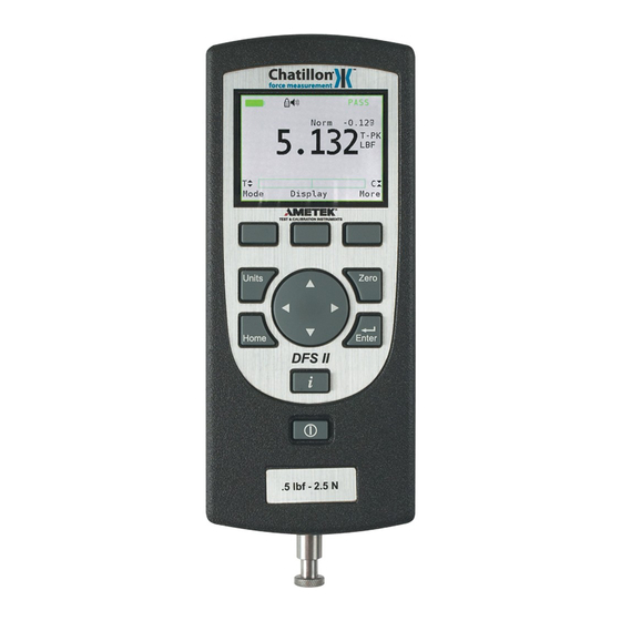
KEYPAD OPERATION The DF II Series gauge has nine (9) keys and a navigation pod. Function Keys There are three (3) function keys located immediately below the gauge display. These keys are mapped to the display prompt above it. Key functions change based on the gauge’s current status or operating mode. -
Page 12: Display Layout
DISPlAY lAYOUT The DF II Series digital force gauge features a TFT-LCD full-color display with backlight. Auto Shutdown ON Measured Result Battery Status Mode Units DISPlAY OPTIONS The DF II Series gauge features the following dis- play options designed to enhance operation and performance. -
Page 13: Changing Display Options
ChANGING DISPlAY OPTIONS From HOME display, select F2 DISPLAY key. This places the gauge in DISPLAY SETUP MODE. DISPlAY UP OR DOWN OPTION The Display Up or Down option allows you to change the orientation of the display. From HOME display, select F2 DISPLAY key. The status line will read “Display Up Down”. If the status line displays “ON”, the “Display Up Down”... -
Page 14: Display Hide Option
DISPlAY hIDE OPTION The Display HIDE option allows you to hide your measured result during testing. This feature is useful when performing blind studies. From the DISPLAY BACKLIGHT screen, depress the F3 DISPLAY key until “Hide Result” appears on the status line. Depress the F1 (NO or Yes) key to enable the Hide Result option. -
Page 15: Changing Mode
ChANGING MODE You may change the DF II Series gauge operating mode by selecting the F1 (Mode) key. From the HOME display, select F1 (Mode) for the following operating modes: Normal Mode When the gauge is in normal mode (NORM), the display will indicate the tensile or compressive load that is applied to the loadcell. -
Page 16: Changing Units
N. DF II Series with capacities greater than 110 lbf (500N) can display results in lbf, kgf and N. DFS II-R-ND gauges with the STS Series torque sensor can display torque in the following units: N-cm, cm-kg, oz-in, lb-in, N-m. -
Page 17: Load Bar Graph
The bar graph fills from the centerline and changes from green to yellow to red indicating proximity to the sensor’s capacity. If the DFS II-R-ND uses the STS torque sensor, the bar graph will change to show “CW” for clockwise and “CCW” for counter-clockwise. -
Page 18: Operating Your Gauge
The DF II Series gauge may be used as a hand- When using the DF II Series gauge with a Chatil- held instrument or mounted to a Chatillon® tester lon® tester, make sure that the gauge is secured for compression and tensile testing. -
Page 19: Saving Results
SAvING RESUlTS The DF II Series can save 20 or 100 results (depnding on model) in the gauge memory. You may use our TCD WEDGE software (p/n NC003164-D) to save infinite results and perform automation, data acquistion and detailed measure- ment analysis. To save a result, apply load to the loadcell shaft. Your gauge will display the load reading. -
Page 20: Viewing Results
vIEWING RESUlTS The DF II Series displays results in the following formats: Active Measured Result Saved Measured Result(s) Pass - Fail Result Load Limt Result Load Average Result Break Detect Result (DFS II Series only) Displaying Peak Mode Result vIEWING ACTIvE RESUlT If you want your DF II Series gauge to display the The DF II Series gauge will display the result in peak result, you should change the gauge to either... -
Page 21: Veiwing Pass-Fail Results
Viewing Saved Result The DFE II will save up to 20 and the DFS II will save up to 100 measured results in its internal memory provided you elect to “SAVE” a result. To view a “Saved Result”, from the Home display, select F3 (More) to access the View display. -
Page 22: Graphing Of Results
Viewing Pass-Fail for Peak Results VIEW results by using the navigation pod UP and If “PASS-FAIL” is enabled (ON), the gauge will DOWN key to scroll through the results saved in indicate a green “PASS” or red “FAIL” result when memory. -
Page 23: Transmit Results
TRANSMIT RESUlTS TRANSMIT DISPlAYED RESUlT The DF II Series can transmit data using its You can transmit results from the View display. RS232, Mitutoyo, USB, Bluetooth (DFS II only) From Home, select F3 (More). This will access the ® or Analog output. The gauge will transmit data to View display. -
Page 24: Transmit Format
TRANSMIT FORMAT The DF II Series gauge will transmit and print re- sults in the following formats: Transmit WITHOUT UNITS (Xmit-O) Transmit WITH UNITS (Xmit-W) Mode Result Value Units Mode Result Value Norm 1 3.8 lb Norm 1 Norm 2 3.8 lb Norm 2 Norm 3... - Page 25 Transmit WITHOUT UNITS (Xmit-O) Transmit Using RS232 The DF II Series gauge will communicate to a serial device using its RS232 output. Connect to the device using the RS232 cable (p/n SPK-DF- RS232). DF II Series Gauge ( p/n SPK-DF-RS232) RS232 Gauge will transmit result WITHOUT units.
-
Page 26: Clear Result From Memory
To access the CLEAR option, select the INFO key ClEAR RESUlT FROM MEMORY (i key). This will change the F2 (Save) key to F2 The DFS II can store up to 100 and the DFE II (Clear). Select F2 (Clear) to clear the displayed can store up to 20 results in instrument memory. -
Page 27: Using Pass-Fail Limits
USING PASS-FAIl lIMITS The DF II Series force gauge allows you to setup PASS-FAIL LIMITS based on either a Range of values or on a Nominal Value. Pass-Fail Limit - Range You may setup your DF II Series gauge to display a green PASS or red FAIL message based on whether or not the measured results falls within an upper and lower setpoint range. - Page 28 USING PASS-FAIl lIMITS Example: The DFS II Series will display green The DFS II Series allows you to setup PASS-FAIL PASS if the measured result is 9.8 lbf and the LIMITS based on either a Range of values or on a Nominal Value was 10.0 lbf and the Bandwidth is Nominal Value.
-
Page 29: Activating Pass-Fail Limits
ACTIvATING PASS-FAIl lIMITS SElECT PASS - FAIl METhOD You have the option of enabling or disabling Pass- There are two Pass-Fail Methods available to Fail Limits. The factory default is Pass-Fail Limits choose from: OFF. Range To enable Pass-Fail Limits, from the Home display, Nominal Value select F3 (More) twice. -
Page 30: Selecting Increments
SElECTING INCREMENTS SElECTING hIGh RANGE lIMIT Increments are associated with the numeric values Use the F1 key to select the HIGH RANGE Pass- displayed by the gauge during setup. You select Fail Limit. The cursor arrow will automatically be the increment you want to use to adjust your setup placed next to the HIGH Limit tag indicating that values. -
Page 31: Selecting Low Range Limit
SElECTING lOW RANGE lIMIT SElECT NOMINAl vAlUE METhOD Use the F1 key to select the LOW RANGE Pass- Use the navigation pod UP and DOWN key to posi- Fail Limit. The cursor arrow will automatically be tion the cursor arrow next to the NOMINAL VALUE placed next to the LOW Limit tag indicating that method. -
Page 32: Select Nominal Value
SElECTING INCREMENTS SElECT NOMINAl vAlUE Increments are associated with the numeric values Use the F1 key to specify the Nominal Value or the displayed by the gauge during setup. You select Bandwidth. When Pass-Fail is ON, the gauge will the increment you want to use to adjust your setup start at the Nominal Value position. -
Page 33: Using Load Limits
USING lOAD lIMITS The DF II Series force gauge allows you to setup and apply LOAD LIMITS. You may setup HIGH and LOW load limits. Load Limits are useful for protecting your gauge or testing system from dam- age or to simply alert you that the gauge or system has exceeded a setpoint value. -
Page 34: Activating Transmit Limits
ACTIvATING TRANSMIT lIMITS Activating buzzer You have the option of enabling or disabling Trans- You have the option of enabling or disabling the mit Limits. The factory default is Transmit Limits Load Limits Buzzer. If ON, the Buzzer provides OFF. you with a visual indicator and an audible indicator when the load measurement exceeds a High or To enable Transmit Limits, from the Home display,... -
Page 35: Selecting Increments
SElECTING INCREMENTS SElECTING hIGh lIMIT SETPOINT Increments are associated with the numeric values The HIGH Limit Setpoint is the load value repre- displayed by the gauge during setup. You select senting the highest COMPRESSION load value the increment you want to use to adjust your setup that you want your gauge to measure prior to it values. -
Page 36: Df Ii Series User Manual
SElECTING lOW lIMIT SETPOINT vIEWING lOAD lIMIT RESUlT The LOW Limit Setpoint is the load value repre- The DF II Series gauge will display “L-T” if a Low senting the lowest TENSION load value that you Load (Tension) Limit has been reached, or “L-C” want your gauge to measure prior to it giving a if a High Load (Compression) Limit has been Load Limit indication. -
Page 37: Using Auto Shutdown
USING AUTO ShUTDOWN ACTIvATING AUTO ShUTDOWN The DF II Series force gauge allows you to config- Automatic Shutdown may be activated from the ure your gauge to automatically shut down if there Main Setup display. From the Home display, select has been no keypad activity or no communication the F3 (More) key twice to access the Main Setup activity for a specified period of time. The purpose display. -
Page 38: About Gauge Communications
DF2 force gauge via the USB port. To verify the USB connection is set up properly between AbOUT GAUGE COMMUNICATIONS the computer and the Chatillon DF2 force gauge The DF II Series force gauges allow you to com- go “Control Panel”, “Hardware and Sound”, municate to external devices using either RS232, “Device Manager”, “Ports (COM &... -
Page 39: Selecting Limits
SElECTING lIMITS (RS232, USb AND blUE- SElECTING bAUD RATE (RS232) The DF II Series allows you to select the required TOOTh®) The DF II Series allows you to transmit an ASCII baud rate when in RS232 mode. signal when a Load Limit has been met. This sig- nal is used to stop crosshead movement on a TCD Position the arrow next to the BAUD tag. -
Page 40: Pinouts
PINOUTS The DF II Series is supplied with a 12-pin female connector to provide RS232, Mitutoyo and analog outputs. The pinout of the connector is shown above. Pin assignments are defined in the table below. sYMBoL PURPosE DEsCRIPTIoN RS-232 Transmitted Data RS-232 Received Data Ground Digital Ground Clock Mitutoyo Clock Ready Mitutoyo Ready Request Mitutoyo Request Data Mitutoyo Data Detect... -
Page 41: Using Hyperterminal Commands
USING hYPERTERMINAl COMMANDS The DF II Series can accept and execute commands through the RS232, USB or the Bluetooth® communi- cations using Hyperterminal. The command set is tailored to make it easy to configure and operate the in- strument under a computer program control. The string commands are sent as strings of ASCII characters. The following string commands are recognized: Command Response Description... -
Page 42: Changing Gauge Polarity
ChANGING GAUGE POlARITY SETUP - POlARITY The DF II Series will normally display TENSION Polarity may be setup from the Main Setup display. measurements as a NEGATIVE number, while From the Home display, select the F3 (More) key displaying COMPRESSION measurements as a twice to access the Main Setup display. -
Page 43: Connecting A Printer
CONNECTING A PRINTER COMMUNICATION CAblES The DF II Series force gauge can transmit infor- The DF II Series gauges are supplied standard mation to a serial data printer or Mitutoyo printer. with an RS232 serial data cable (p/n SPK-DF- Printing is performed from the View display using RS232). -
Page 44: Connecting A Serial Printer
CONNECTING A SERIAl PRINTER CONNECTING A MITUTOYO PRINTER Connect the DF II Series gauge to the serial Connect the DF II Series gauge to a Mitutoyo printer using the gauge output connector and the printer using the optional Mitutoyo cable (p/n serial cable provided with the gauge (p/n SPK- NC000654). -
Page 45: Using Remote Sensors
The SLC Sensor is inserted into the 15-pin connec- sor is inserted into the 15-pin connector located on tor located on the side of the DFS II-R-ND gauge. the side of the DFS II-R-ND gauge. The gauge will The gauge will automatically recognize the sensor automatically recognize the sensor type and its as- type and its associated capacity and resolutions. -
Page 46: Specifying The Correct Sensor
SPECIFYING ThE CORRECT SENSOR UNDERSTANDING FUll SCAlE CAPACITY The single, most-common problem when measur- The SLC and STS Series sensors have accura- ing load or torque is caused by the use of a sensor cies based on “full scale”. The accuracy of these that is not appropriate for the application. -
Page 47: Powering Your Gauge
POWERING YOUR GAUGE POWER UP WITh STS SENSOR The DFS II-R-ND requires a sensor for it to per- When you connect a calibrated STS Sensor to the form as a force or torque gauge. The DFS II-R-ND DFS II-R-ND, the gauge will display the STS model... -
Page 48: About Slc Sensors
Carefully mate the connector on the SLC or STS sensor to With the DFS II-R-ND turned OFF, insert the SLC the connector on the side of the DFS II-R-ND gauge. connector making sure to properly “seat” the individual pins. Once the sensor is connected, secure the sensor by tightening the mounting screws. -
Page 49: Handling The Slc Sensor
Do not connect the sensor when the pow- er to the DFs II-R-ND is oN. Make sure that power to the DFS II-R-ND is OFF before connecting your sensor. Do not disconnect the sensor by pulling on the cable. Grasp the connector and pull the sensor from the DFS II-R-ND gauge. -
Page 50: Mounting Slc Sensor To Tester
MOUNTING SlC SENSOR TO TESTER The SLC Series loadcell sensor may be used with Chatillon® force testers. A mounting adapter is required to secure the sensor to the following testers: Tester Adapter Part No. MT150 SPK-MT-0001 & NC000300 MT500 SPK-MT-0004 & NC000300... -
Page 51: Using Software
USING SOFTWARE Your DF II Series gauge can be operated using our TCD WEDGE applications software. TCD WEDGE software communicates between your DF II Series force gauge and your Windows ® based personal computer. Measurement data is sent from your gauge via the RS232 cable, USB cable or Bluetooth , to a Microsoft Excel... -
Page 52: Using Load Averaging
USING lOAD AvERAGING The DF II Series force gauge allows you to perform two different types of Load Averaging tests: Load Average Force-Based Load Average Time-Based lOAD AvERAGE FORCE-bASED lOAD AvERAGE TIME-bASED This load averaging test allows you to set a pre- This load averaging test works identical to the load limit value or load threshold. -
Page 53: Load Average Setup
lOAD AvERAGE SETUP SElECTING INCREMENTS To setup the Load Average function, from the Increments are associated with the numeric values Home display depress F3 (More) three times. Use displayed by the gauge during setup. You select the navigation key to position the arrow at the the increment you want to use to adjust your setup “Load Average”... -
Page 54: Selecting Preload Limit
SElECTING PRElOAD lIMIT SElECTING TIME lIMIT The “Preload Value” is the threshold value or “trigger The “Time Value” functions with the “Preload Value”. point” that defines the “Start” and “End” of the It represents the operand “OR” when selected. The average function. gauge will “start” to average once the preload value is acheived. - Page 55 Select the increment value using the LEFT or PERFORMING A FORCE-bASED lOAD RIGHT navigation key. Increments for time may be AvERAGE TEST either 1, 10 or 100 and represent seconds. Time is From the Home display, depress the F1 (Mode) only displayed in seconds.
-
Page 56: Test Annuciators
TEST ANNUCIATORS PERFORMING A TIME-bASED lOAD The Load Averaging feature employs three types of AvERAGE TEST annunciators to: From the Home display, depress the F1 (Mode) key until the gauge displays “LAVt” for mode. The 1. Signal the START of your Test, “LAVt”... -
Page 57: Using Break Detection
The DFS II Series force gauge allows you to per- USING bREAK DETECTION (DFS II ONlY) form two different types of Break tests: Break Detection is used when you want to capture the break load of a sample. This function is use- Sharp Break Test (95% Drop Fixed) ful especially with samples that characteristically Percentage Drop (% Break) Test... -
Page 58: Sharp Break
ShARP bREAK PERCENTAGE bREAK The Sharp Break test looks for a 95% Drop from The Percentage Break test allows you to specify the maximum load. In this test, you can determine the % Drop from the Peak Load. If you set the % the “Break Detect Point”... -
Page 59: Break Detection Setup
bREAK DETECTION SETUP SElECTING INCREMENTS To setup the Break Detection function, from the Increments are associated with the numeric values Home display depress F3 (More) three times. Use displayed by the gauge during setup. You select the navigation key to position the arrow at the the increment you want to use to adjust your setup “Break Detect”... -
Page 60: Selecting Break Point
Break Point - Percentage Break Method SElECTING bREAK POINT To set the Break Point in a Percentage Break setup, The “Break Point” is the break detector value or the establish the correct increment value. Position the “break trigger”. It is the force value that must be arrow cursor next to the label “BkPt”. -
Page 61: Selecting % Drop Value
SElECTING % DROP vAlUE The “% Drop” is the percentage drop value. This represents how much the measured load must drop from a previous maximum load for the DFS II Series gauge to identify the break load. A Sharp Break has a fixed percentage drop of 95%. It presents the 95% value from full scale. If the maximum load is 100 lbf and the % Drop is 95% (for a Sharp Break), the break load will be at 95 lbf. -
Page 62: Performing A Sharp Break Test
A pull to break test will use the mode “STBk”. Af- Compress (Push) the sample (manually or using fix your sample to the grip or fixture and zero the a Chatillon® tester). The load applied to the load gauge. Press the Zero key to zero the load effects sensor is displayed during the test. -
Page 63: Performing A Percentage Break Test
Pull to Break A pull to break test will use the mode “%TBk”. Affix Compress (Push) the sample (manually or using a your sample to the grip or fixture and zero the gauge. Chatillon® tester). The load applied to the load Press the Zero key to zero the load effects caused sensor is displayed during the test. by the sample weight and fixture (tare out). When the sample breaks (physically breaks) or Pull the sample (manually or using a Chatillon®... -
Page 64: Viewing Your Break Test Result
vIEWING YOUR bREAK TEST RESUlT TRANSMITTING YOUR bREAK TEST The DFS II Series gauge will display the following RESUlT information at the completion of a test: From the SAVE Mode, select the F1 (Xmit) key From this display, you may record your reading to transmit information through the DFS II Series manually;... - Page 65 When the F2 “XmitAll” key is selected, the gauge will transmit all information “Saved” in the gauge memory for the %Bk mode. The following informa- tion is transmitted: Result Number (1- 10) Break Load with or without Units Maximum Load with or without Units Peak Load with or without Units % Drop Value Break Point Value...
-
Page 66: Saving Your Break Test Result
SAvING YOUR bREAK TEST RESUlT You may save up to 100 results in the DFS II Series gauge memory. If you are saving informa- tion, remember that the gauge can only save 100 results. It is also important for good operating practice to save like mode information. -
Page 67: Applying Statistics To Your Break Test Result
APPlYING STATISTICS TO YOUR bREAK TEST RESUlT The DFS II Series gauge will calculate statistics for your Break Test results saved in the gauge memory. The gauge will calculate and display the following: Mean Coefficient of Variation (COV) % Difference Standard Deviation The “Statistics” function is part of the “Save” function within the DFS II Series gauge. -
Page 68: View % Difference
View % Difference % Difference is displayed after COV. The DFS II Se- ries gauge will display the % Difference between successive results beginning with Result #1 compared to Result #2. Use the LEFT and RIGHT navigation keys to change Result Numbers. Select the F1 (Xmit) key to transmit the displayed information through the selected communications port. -
Page 69: Using Filters
USING FIlTERS FIlTER SETUP The DF II Series digital force gauge supplies two The DF II Series filters are setup from the Main types of filtering. Filtering may be useful with Setup Menu. From the Home display, press the F3 applications that are “noisy” or susceptible to (More) key three times. vibration effects, e,g., gauges measuring extremely low forces below 250gf. -
Page 70: Display Filter Setup
Use the UP or DOWN navigation key to position PEAK FIlTER SETUP the cursor arrow next to the “Filters” option. Select From the Display Filter setup, depress F1 (Peak) to ENTER. change the Peak Filter setup. Selecting F1 (Peak) will position the cursor arrow next to the “Peak” DISPlAY FIlTER SETUP label. -
Page 71: Using Contact Closure
USING CONTACT ClOSURE (DFS II only) The DFS II Series digital force gauge can be used to identify two types of contact closure events: Break (Open) Connection Make (Closed) Connection The DFS II Series digital gauge will freeze its display at the force that was required to sense an event change in a switch operation. -
Page 72: Contact Closure Operation
CONTACT ClOSURE OPERATION The contact closure feature must be specified in the gauge setup and the gauge must be placed in Contact Closure Mode. When in Contact Closure mode, the DFS II Series gauge will “freeze” the display at the load that caused a switch “make” or “break”. -
Page 73: Contact Closure Setup
CONTACT ClOSURE SETUP Contact closure is specified using the DFS II Gauge Setup menu. From the HOME display, press F3 (More) four times to get to the CONTACT CLOSURE option. Use the UP or DOWN navigation key to cursor to the CONTACT CLOSURE option and select ENTER. DF II Series User Manual... -
Page 74: Contact Closure - On/Off
CONTACT ClOSURE - ON/OFF If this option is selected, the DFS II Series gauge will not freeze its display when a switch event has oc- curred. There is no Contact Closure Mode available. Select F1 (ON/OFF) to enable or disable contact closure. -
Page 75: Specifications
Color Color Memory (No. of Saved Results): Note : SLC-02000, SLC-05000 and SLC-10000 capacities used with the DFS II-R-ND have a calibration accuracy of +0.5% of full scale. Common Specifications to all DF Models Temperature Rating Operating Temperature: to 100... -
Page 76: Dimensions
DIMENSIONS Gauge with Integral load Cell Sensor Gauge with Remote load Cell Sensor 1 . 6 2 [ 4 1 . 1 m m ] 2 . 8 6 [ 7 2 . 6 m m ] 1.62” (41.1 mm) 2.86”... - Page 77 DF II Series User Manual...
- Page 78 DF II Series User Manual...
- Page 79 DF II Series User Manual...
- Page 80 DF II Series User Manual...
- Page 81 DF II Series User Manual...
- Page 82 DF II Series User Manual...
- Page 83 DF II Series User Manual...
- Page 84 DF II Series User Manual...
-
Page 85: International Symbols
This product is RoHS and China RoHS compliant. This symbol indicates the equipment contains some restricted hazardous substances above the recommended level, and may offer potential harm to the environment after 15 years from date of manufacture. www.chatillon.com Denmark Singapore lloyd Instruments ltd AMETEK Denmark...
Need help?
Do you have a question about the DFS II-R-ND and is the answer not in the manual?
Questions and answers