
Summary of Contents for Aviat Networks CTR 8540
- Page 1 CTR 8540 GETTING STARTED ® HARDWARE INSTALLATION Rev. 003 December 2014 260-668255-001...
-
Page 3: Copyright & Terms Of Use
Inc. To request permission, contact techpubs@aviatnet.com. Warranty Aviat Networks makes no representation or warranties with respect to the contents hereof and specifically dis- claims any implied warranties or merchantability or fitness for any particular purpose. Further, Aviat Net- works reserves the right to revise this publication and to make changes from time to time in the content hereof without obligation of Aviat Networks to notify any person of such revision or changes. -
Page 4: Table Of Contents
Table of Contents Copyright & Terms of Use Table of Contents CTR 8540 Getting Started: Installation Purpose Introduction Unpacking Installation Installation Requirements Installation Procedure Adding Modules to CTR Module Installation Requirements Module Installation Procedure Power Supply Next Steps Health & Safety... -
Page 5: Ctr 8540 Getting Started: Installation
Purpose This Getting Started Guide is intended for use at new installations. It overviews installation of the CTR 8540 chassis and optional plug-in modules, and addresses associated health and safety requirements. Beyond this point a user is expected to make use of the CTR Installation Guide, which includes guidance on associated RF units (ODUs, IRU 600), antennas, antenna alignment, and much more. -
Page 6: Table Of Contents
QAM, adaptive coding and modulation (ACM), and extensive protection and co-path configurations. Unpacking Carefully unpack the CTR 8540 from its transport box and check that items supplied are in agreement with the shipping documentation, are as-ordered, and are undam- aged. -
Page 7: Installation Requirements
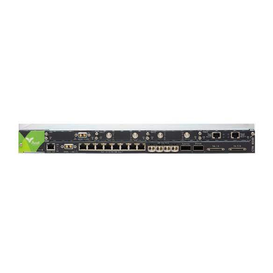
CTR INSTALLATION GUIDE CTR 8540 Front Panel Figure 1-1. Item Description Fan Tray Fan tray houses the Fan module with four software controlled fan units. The Fan is a compulsory module. RJ-45 V24 Main- Port for serial data connection of PC craft tool. - Page 8 CTR 8540 GETTING STARTED: INSTALLATION Function/Requirement Priority Details The CTR and its associated dc power supply must be installed in a Restricted access restricted access area such as a secure equipment room, closet, or cabinet. CTR requires 44.5 mm (1RU) of vertical rack space and 300 mm rack Required Rack Space depth (CTR chassis depth is 240 mm).
-
Page 9: Installation Procedure
Installation Procedure This procedure is for rack-mounting CTR 8540. Fit the rack mounting ears to the chassis with the grounding stud to left or right side for the most direct ground wire path to the rack ground bar. -
Page 10: Adding Modules To Ctr
SFP option. Fit E1/DS1 tributary cables as required. For information on the available tributary cable sets, refer to the CTR 8540 Installation Guide. Carry out a complete check of the installation. When checked and correct: If option modules are to be installed, proceed to the next topic. -
Page 11: Module Installation Requirements
CTR INSTALLATION GUIDE PWR+AUX Module Install in slot 1 only to provide power supply backup and configurable auxiliary data channels, alarm input and output (I/O) options. Power supply backup operation is identical to that provided by the PWR module. NOTE: The PWR+AUX module is not available at SW release 2.4. - Page 12 CTR 8540 GETTING STARTED: INSTALLATION Function/Requirement Priority Details Slot Assignment All slots filled All slots must be filled with a module or have a cover plate fitted. Failure to do so will compromise EMC integrity and distribution of fan cooling air.
-
Page 13: Module Installation Procedure
24 Vdc (+ve or -ve) to -48 Vdc for connection to the CTR and optional PWR module. Contact Aviat Networks or your supplier for availability. CAUTION: The dc power supply must be UL or IEC compliant for SELV (Safety Extra Low Voltage) output (60 Vdc maximum limited). - Page 14 CTR 8540 GETTING STARTED: INSTALLATION A D-sub M/F 2W2 connector is fitted at one end, wire at the other. The cable is nominally 3 m (10 ft). The wires are 4 mm2 (AWG 12). The blue wire must be connected to live (-48 Vdc); the black wire to ground (+48 Vdc).
-
Page 15: Next Steps
CTR 8500/8300 Getting Started Guide: Configuration CTR 8500/8300 CLI Reference Manual CTR 8500/8300 Configuration Guides (protocol-specific) for ESMC, ECFM, EOAM, VLANs, IP, QoS, STP, LAG To configure CTR 8540 using its Web GUI, refer to the CTR Portal Manual 260-668240-001 DECEMBER 2014... -
Page 16: Health & Safety
CTR 8540 GETTING STARTED: INSTALLATION Health & Safety Personnel involved with the installation, configuration, or servicing of CTR 8540 must be aware of and comply with the following health and safety requirements. CAUTION: For comprehensive health and safety requirements, including those for installation of radio transceiver options and tower-mounted devices, refer to the CTR 8540 Installation Guide. - Page 17 Fan card houses hazardous moving parts. Restricted Access CTR 8540 must be installed in restricted access sites. The indoor unit and associated power supply must be installed in restricted areas, such as ded- icated equipment rooms, closets, cabinets, or the like. Access to any tower and antenna location must be restricted.
- Page 20 260-668255-001 WWW.AVIATNETWORKS.COM...
Need help?
Do you have a question about the CTR 8540 and is the answer not in the manual?
Questions and answers