Table of Contents
Advertisement
Electric Steps
Equipped with a Permanent Magnet Motor and Control Unit
(For steps using control units 9009506000, 909506000, 909507000, or 909508000
Single Steps
Double Steps
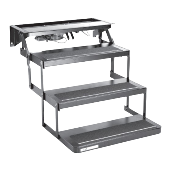
Triple Steps
Owner's
Manual
© 9/02 Kwikee Products Co. Inc.
Kwikee #1422255
Table of Contents
Extending Step to Install
Van Steps
#875
2
2
3
3
4
4
5
6
7
9
10
12
13
Advertisement
Table of Contents

Related Manuals for Kwikee 875

Summary of Contents for Kwikee 875
-
Page 1: Table Of Contents
Owner's Manual #875 © 9/02 Kwikee Products Co. Inc. Kwikee #1422255 Electric Steps Equipped with a Permanent Magnet Motor and Control Unit (For steps using control units 9009506000, 909506000, 909507000, or 909508000 Table of Contents Warranty Information Step Identification Information... -
Page 2: Warranty Information
Warranty This document has been modified from the original Kwikee 09/02 release. All former references to the Kwikee warranty and contact information were removed. For all concerns or questions, please contact Lippert Components, Inc. Ph: (574) 537-8900 | Web: lci1.com | Email: customerservice@lci1.com... -
Page 3: Introduction
“senses” the larger current off. When the ignition is switched on, the troubleshooting of any Kwikee electric draw and shuts off power to the motor. function of the power switch is disabled step manufactured after January 1999... -
Page 4: Installation
Introduction For easier installation, extend the FIGURE 1: Extending the step for installation. step by placing it upside-down on its mounting surface. Understep light (not available on WARNING: Making the all step models) Motor wire connections assembly 12 AWG green detailed in this ground to step top procedure will cause the step to... -
Page 5: Wiring The Step
Understep light (not available on INSTALLER NOTES: all step models) NOTE: For Van Step wiring kits order part #7541000 Motor Kwikee recommends wiring the assembly 12 AWG green step to the vehicle battery instead ground to step top Step Wiring of the “house”... -
Page 6: Door Switch
If the rocker switch is supplied by mounting position. Wiring to the installation is acceptable. Kwikee, the power switch may be switch should come up through the mounted as is by cutting a 1 9/16" x Some experimentation with the hollow door frame. -
Page 7: Step Test Procedures
These Step Test Procedures have been FIGURE 5: Step test procedures wiring diagram Understep light provided to troubleshoot and test all of (not available on the Kwikee automatic electric step all step models) Motor functions. They are designed to initially assembly... - Page 8 Step Test Procedures 14. To check the door switch, connect Testing the Motor battery itself, or a poor ground. If the voltage reading is zero (0) volts, check a voltmeter between the red wire from 11. Disconnect the two-way connector the step fuse/circuit breaker, all the 4-way connector (vehicle half) and between the step motor and the control...
-
Page 9: General Service Notes
This is erratic operation of the step. Poor common questions about Kwikee caused by the momentary charging of ground connections may also cause electric steps. Due to the number of erratic operation of the step. -
Page 10: Step Motor Parts Key
Step Motor Parts Key The motor assembly part numbers listed in the gray box below contain the motor, linkage, gears, and gear box for the corresponding step series number. Step Motor Series # Assembly Description of Step 22 Series Step #909502000 Double tread step;... -
Page 11: Step Motor Assembly Diagram
Step Motor Assembly Diagram This view of the motor is rotated 180° of actual orientation to the step frame. LINKAGE ASSEMBLIES TWO-WAY CONNECTORS TO THE CONTROL UNIT Drive link shaft Adapter extension length = 2 7/16" Pigtail Drive link shaft extension length = 2 9/16"... -
Page 12: Step Motor Assembly
Instructions for Step Motor Assembly Instructions for removing the motor and Remove the cotter pin (Item #8) Gear case removal: Unbolt the gearbox from the step frame and from the clevis pin (Item #9) at the motor mounting plate (Item #13) from disassembly of the motor gearbox. -
Page 13: Maintenance And Lubrication
KwikLubeTM Spray Figure 4 - on step models Grease is specially formulated to equipped with plastic cover, this cover lubricate Kwikee Electric Steps and is will have to be removed to lubricate recommended for lubricating all moving center bearings. Lubricate bearings parts. - Page 14 Maintenance: Adjusting the Cam Stops 24, 25, 27, 32, 34, 35, 36, 38, and 40 Series Steps WARNING: When the Kwikee steps are fitted with adjustable The cam stops are located under the cam stops are out of cam stops on the step frame that help...
Need help?
Do you have a question about the 875 and is the answer not in the manual?
Questions and answers