
Summary of Contents for cad2cnc Samba R.E.S. Evo
- Page 1 P a g e cad2cnc presents the Written by: Leonard MacKey Pikes Peak Soaring Society Visit us at:...
- Page 2 P a g e THANK YOU! This guide would not have been possible without the cooperation and assistance of fellow fliers and builders, particularly Greg M. (‘glidermang’ on RC Groups). Greg is the author of the very informative Samba EVO Build Thread .
-
Page 3: Table Of Contents
P a g e Table of Contents Contents Samba RES EVO ............................. 4 Kit Specifications ............................4 Required to Build ..........................4 Recommended Servos .......................... 4 Recommended Throws ......................... 4 Technical specifications ........................4 Getting Started ............................5 Horizontal/Vertical Stabilizers ........................5 The Fuselage ............................. -
Page 4: Samba Res Evo
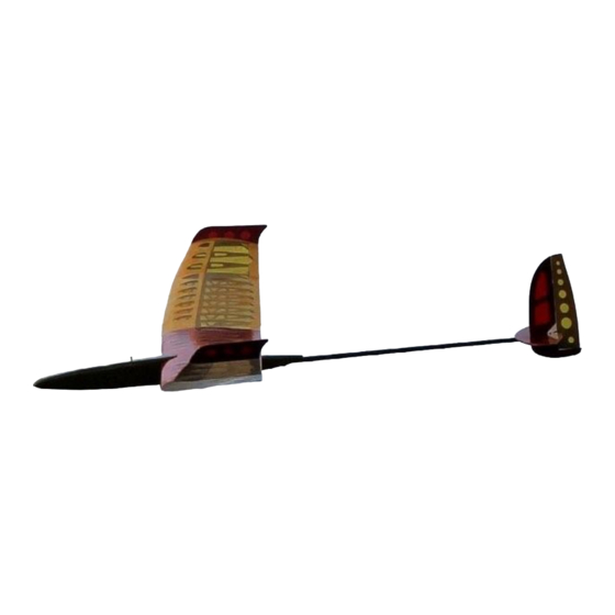
P a g e Samba RES EVO Dear Builder, Samba RES EVO Welcome to the family The Samba EVO is an F3-RES (Rudder/Elevator/Spoiler) competition RC glider with outstanding flight performance. The kit was designed using the latest techniques and precisely made from high quality materials using both laser cutting and CNC milling. -
Page 5: Getting Started
P a g e Getting Started Most components do not require building over the plans. You can simply cover your board with some type of release film (cling wrap, etc.) and build away! However, feel free to use the plans if you prefer. - Page 6 P a g e 4. Dry fit and pin the horizontal stab parts to your board using the ruler as a reference edge. 5. Join the parts with thin CA, or if you prefer, a thin aliphatic white glue such as Super Phatic.
-
Page 7: The Fuselage
P a g e The Fuselage HINT Basic Construction The fuselage is a contemporary BEFORE GLUING, TAKE THE TIME TO SAND OFF AS MUCH former-plywood-balsa design OF THE CHAR AND BURNT WOOD AS POSSIBLE FROM THE composed of interlocking laser cut CUT EDGES OF THE PIECES. - Page 8 P a g e is sized for HS-55 type servos and one for smaller KST X08 size servos. The tray between SP2 & SP3 is the piece cut for larger HS-55’s. The KST X08 openings are in the forward nose plate. The formers are somewhat complicated with many notches and cut-outs; however, they are precisely located and the tray will fit on the formers correctly at only one position.
- Page 9 P a g e Some modelers add a medium CA fillet at the points where the stringers pass through the plywood formers as reinforcement for the joint. 15. Repeat with the second short pine stick for the other side. 16. Install the T-nut in the wing hold down. 17.
-
Page 10: Shaping The Fuselage
P a g e | 10 careful not to allow cement to get into the plastic tube. Trim the tube flush with the forward end of the latch former. 27. Glue the other cut plastic tube into the other latch former and trim it flush. This acts as the receptacle for the latch when it is engaged. - Page 11 P a g e | 11 grit) or a small hand plane to flatten the corners. Do not attempt to round them at this time. 6. When the corners are flattened to your satisfaction, use a flat sanding block with 120-150 grit sandpaper to round and blend the corners from nose to tail.
-
Page 12: Wing Center Section
P a g e | 12 Wing Center Section This part of the build goes quickly, particularly if you’re using CA. It HINT can be divided into three main phases: 1. Wing preparation where you sort out all the bits and pieces, BUSINESSES THAT SELL glue the longer parts together (top sheeting, spar, trailing GRANITE COUNTER TOPS... -
Page 13: Spar And Ribs
P a g e | 13 8. Join the bottom sheeting, spar, and trailing edge using the same technique as above. 9. When the longer parts are complete, pin the trailing edge as accurately as you can over the plans. Note: Building over the plans is not strictly necessary. If you are building over the plans, trust the components. - Page 14 P a g e | 14 4. Fit ribs R1, R3, the middle R4, and R9 in place on both sides of the centerline, trapping the carbon fiber in the notches pre-cut into the ribs and aligning it with the bottom sheet. 5.
- Page 15 P a g e | 15 for the carbon fiber wing hold down pin at the leading edge. NOTE: Remove any char from the plywood pieces. 18. Dry fit the plywood spar rib reinforcement between the two R1 ribs in front of the spar. Sand if necessary. 19.
-
Page 16: Leading Edge, Spoiler Box, And Wing Hold Down Support Plate
P a g e | 16 24. Dry fit the other carbon fiber spar into the top notches of the ribs against the sheer web. Be sure to seat it completely along its length from R9L to R9R. When all is as it should be, remove the CF spar, roughen it and glue it in place using medium CA. -
Page 17: Wing Hold Down Support & Top Sheeting
P a g e | 17 8. Roughen the outside of the two pieces of 5 mm aluminum tubing that serve as wing joiner bushings. Trial fit them through R9 and into R8 for each end of the center section, then use either epoxy or medium CA to secure them in place. -
Page 18: Installing The Spoiler
P a g e | 18 6. The next step will be to install the top sheeting. Pin the trailing edge to the building board and pin the ribs aft of the spar. This helps to guarantee a warp free wing. 7. - Page 19 P a g e | 19 Mounting the spoiler servo is a builder option, but many choose to glue the mounting frame into the servo bay then use thin double-side tape to mount the servo to the balsa. Hot glue or any other builder preferred method will work as well.
-
Page 20: Mid-Wing
P a g e | 20 9. Mount the spoiler control horn as shown in the image on the right. Note that the horn appears to be mounted flush with the forward edge of the spoiler with the extension facing aft. Also, the opening for the horn needs to be wider than a simple knife cut. - Page 21 P a g e | 21 1. If you choose to build over the plans, layout the wing plans on a building board, covering them with a non-stick plastic such as cling wrap. Locate and lay out the needed parts where you can reach them, but leave room for you to work.
- Page 22 P a g e | 22 8. Now attach the lower wing WARNING! sheet/strip to the forward rib bottoms. These are the ~400 mm (~15-3/4”) x ~15 mm (~9/16”) JUST LIKE R9 IN THE CENTER SECTION, R10 AND R18 HAVE POLYHEDRAL BUILT INTO pieces of slightly curved ~2 mm (~1/16”) balsa.
-
Page 23: Wing Tip
P a g e | 23 19. Trim the sub-leading-edge close to length and plane/sand a bevel it to match the rib profile leaving the front flat. 20. Glue on the top sheeting. Align it to the end of R10. Pin it and weigh it down to ensure good contact. -
Page 24: Building The Winglet
P a g e | 24 4. Check to see that all is aligned properly, then use thin CA to glue the parts together. 5. Add the upper spar, check to see that it is fully seated into the rib notches and flush with the sheer webbing, then glue. -
Page 25: Covering The Wing
P a g e | 25 To build the winglet: 1. Locate and identify the three pieces that make up the winglet. 2. Glue the two pieces of the winglet together. 3. Trial fit and then glue the triangular stock to the outside of R22 with the long side (hypotenuse) facing outboard! That becomes the edge to which you will glue the winglet blade. -
Page 26: Attaching The Fuselage And Boom
P a g e | 26 3. Trial fit the two stab parts together. NOTE: It is vital that the two stabilizers are at 90° to each other in both the vertical and horizontal dimensions! 4. Alignment horizontally (fore/aft) is achieved by carefully aligning the bottom edge of the horizontal stab with the bottom edge of the cut for the boom in the vertical stab. -
Page 27: Rigging The Pull-Spring Control Setup
P a g e | 27 Rigging the Pull-Spring Control Setup The Samba is designed for a ‘pull-spring’ control arrangement, where control lines are run from the servo arm through the boom to a control horn on the elevator or rudder. The control surface is deflected by a piece of 0.04 mm (~0.00157”) spring wire (supplied). - Page 28 P a g e | 28 To build the Pull-Spring Control: 1. Hinge the rudder and elevator using the method of your choice. This manual uses taped V-hinges. 2. Locate the required parts. The control horns are in the 1.5 mm (~1/16”) ply sheet that contained the polyhedral braces.
-
Page 29: Installing The Electronics
P a g e | 29 16. Use a piece of spring wire inserted through the fuselage to fish the threads into the servo compartment. 17. Feed the thread from the top of the servo arm down through the hole in the servo arm then up through the adjacent hole. -
Page 30: Balancing
P a g e | 30 Balancing The balance of an airplane can determine whether or not you enjoy many hours of reward NOTE for your effort or whether or not you bring TO SOME EXTENT, THE EXACT home the pieces in a plastic bag. Most pilots LOCATION OF THE CENTER OF GRAVITY are aware of the importance of establishing a IS A PILOT PREFERENCE. -
Page 31: Control Setup
P a g e | 31 To use the CG jig: 1. Locate the two small thru holes in the fuselage ~72-mm (~2.75”) from the wing leading edge and just below the top stringer. Open them with a wire or pin. 2. - Page 32 CONGRATULATIONS! Your Samba EVO is now ready for its first flight. May it be the first of many! We hope that you have enjoyed building the Samba EVO as much as we’ve enjoyed bringing it cad2cnc to you. Please check out our website at: (http://www.cad2cnc.ch/) for additional kits and building opportunities.
-
Page 33: Appendix 1: List Of Terms Used On The Plan
P a g e | 33 Appendix 1: List of Terms Used on the Plan NOTE THIS IS NOT A LITTERAL TRANSLATION IN THE STRICT SENSE OF THE WORD, BUT RATHER A ‘WORKING’ GLOSSARY OF THE LABLES AND TERMS USED ON THE PLAN. Term or Phrase Working Translation 0.04 mm Stahldraht...
Need help?
Do you have a question about the Samba R.E.S. Evo and is the answer not in the manual?
Questions and answers