
Related Manuals for WELL.D MEDICAL WED-3000V

Summary of Contents for WELL.D MEDICAL WED-3000V
-
Page 1: User Manual
WED-3000V Veterinary Ultrasound Scanner User Manual SHENZHEN WELL.D MEDICAL ELECTRONICS CO. LTD. -
Page 2: Table Of Contents
Preface ................................1 Statement ..............................1 Manufacturer's warranty .......................... 1 Matters need Attention ..........................2 Safety labels ............................2 General tips for equipment operation ...................... 3 General Safety Message .......................... 3 1 Summary ..............................6 1.1 Brief Introduction ..........................6 1.2 Range of application .......................... - Page 3 5 Image processing ............................ 22 5.1 Overview ............................22 5.2 Cine loop ............................22 5.3 Static image storage (SAVE) ......................23 5.4 Image export (SVLOAD) ........................ 23 5.5 ZOOM ............................. 24 5.6 Upside down ............................ 24 5.7 Turning around ..........................24 5.8 Pseudo color procedure ........................
-
Page 4: Preface
is trade marks of Shenzhen Well.D Medical Electronics Co., Ltd. Any abuse of these trade marks without permission will be sued to assume legal responsibility according to laws. -
Page 5: Matters Need Attention
Shenzhen Well.D Medical Electronics Co., Ltd. shall not be responsible for losses, damages or injuries caused by delayed service request. When there is problem with the products, please contact Shenzhen Well.D Medical Electronics Co., Ltd. and explain the equipment model, serial number, date of purchase and the problem. -
Page 6: General Tips For Equipment Operation
Handle carefully Temperature limit Upward Piling layer limit Keep dry Protect against heat General tips for equipment operation Note: The equipment is use only for veterinary. ◆ In operation Heat radiation holes are strictly prohibited to be covered. After closedown, do not switch on the equipment within 2 - 3 minutes. On scanning, if any abnormal case is found, stop scanning immediately and shut down the equipment. - Page 7 The equipment shall be operated by qualified operating staff or under their instructions. Do not open the equipment and change the parameters without permission. If necessary, please turn to for Shenzhen Well.D Medical Electronics Co., Ltd. or its authorized agent for service.
- Page 8 12. Shenzhen Well.D Medical Electronics Co., Ltd. shall not take any responsibility for any risk resulted from unauthorized re-fitment by the users. 13. To disconnect the equipment from the power supply network by unplug the adapter from the power supply network.
-
Page 9: Summary
1 Summary 1.1 Brief Introduction This equipment is high resolution linear/convex Veterinary Ultrasound Scanner. It adopts micro-computer control and digital scan converter (DSC), digital beam-forming (DBF), real time dynamic aperture (RDA), real time dynamic receiving apodization, real time Dynamic receiving focusing (DRF), Digital frequency Scan (DFS), frame correlation technologies to endue its image with clarity, stability and high resolution. -
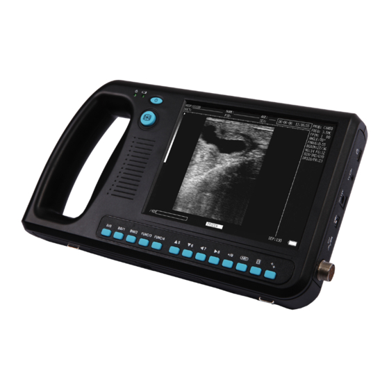
Page 10: Appearance
1.3 Appearance Front sketch Side interfaces sketch Top knobs sketch 1.4 Technical Specificatio WED-3000V MODEL L1-5/7.5MHz C1-12/20R/5.0M 35LV150CP C1-11/50R/3.5M HF linear Probe LV2-4/6.5MHz Backfat probe Hz convex Rectal micro-convex ≥80 ≥140 ≥90 ≥160 Detect Depth(mm) ≤3 (Depth≤ ≤1 (Depth≤ ≤3 (Depth≤... -
Page 11: Electric Principle Block Diagram
Monitor size 7 Inch TFT LCD Display mode B、B+B、4B、B+M、M Image gray scale 256 Scale Image storage 64 Frame Dynamic range 0-192dB(Adjustment range 64-192dB) ≥340 Frame Cine loop Scan depth 70mm~240mm Image flip Up/down, left/right Focus Focus Number, Focus position Body mark Image Process Pseudo color, GAMA, Image Smoothen, Histogram Probe Frequency... -
Page 12: Standard Configurations
1.6 Standard configurations Main unit power adapter Battery 35LV150CP Backfat probe Adapter power supply cord Coupling gel 250ml Manual Final examination report Packing List 1.7 Optional pieces LV2-4/6.5MHz Rectal probe ... -
Page 13: Installation
2 Installation 2.1 Operation environmental requirements Environment temperature range: 0℃~+40℃ Relative humidity range: ≤80% Atmosphere pressure range: 70KPa~106Kpa Power supply: a.c.100V~240V,50Hz±1Hz/60Hz±1Hz Avoid strenuous vibration during operation; Keep away from equipments with high electric field, high magnetic field and high voltage; avoid strong sunlight on the display; Keep the equipment well-ventilated, damp proof and dustproof. -
Page 14: Installing And Disassembling Probes
2.3 Installing and disassembling probes Install probes: The probe jack lies in the bottom of the right side of the equipment. Adjust the probe plug mark position and insert it, turn the plug lock sleeve counter-clockwise. There is only one plug jack which is also compatible for those optional probes (refer to figure). -
Page 15: Power Supply
2000 times of efficient connection and disconnection of the probes are guaranteed.Once the probe is connected with the main unit, do not unplug nor plug it at discretion in case poor contact happen. Warning: The probe should be protected from felling off or crashing and the manufacturer assumes no responsibility for the kind of hazard. -
Page 16: Battery Charging
Warning: It is prohibited to use any other power supply except the standard adapter as the external power supply for the main unit. 2.5 Battery charging There are 3 ways to charge the battery. 2.5.1 Charging through main unit 1. Install the battery correctly into the main unit. 2. -
Page 17: Charging Through Auto-Charger
When the " " indicator light on the adapter turns into red, the battery is in charging; when the " " indicator light turns into green, the battery is fully charged. (Refer to figure). Charging through adaptive line 2.5.3 Charging through auto-charger 1. -
Page 18: Operating Procedures
3 Operating procedures 3.1 Introduction of keyboard Power indicator Display area Power switch Freezes button Probe socket Function button Mouse As a supplement of computer operation, mouse can make the measurement faster and more convenient. PC mouse of which the left button, middle button and right button have specific functions is applied to the equipment. -
Page 19: Display Interface
3.2 Display interface Hospital name Patient name Patient age probe type Patient gender System date, time Probe frequency Doctor name Focous, focal distance Current scanning angle Medical record number Scanning direction mark overall gain Frame correlation value Brightness, image smoothing, grey correction Near field, far field gray scale band Dynamic range, frame frequency... -
Page 20: Image Parameter Adjustment
4 Image parameter adjustment 4.1 Display mode switching B mode switching Press “B/0”button in the real-time scanning mode to switch current image to real-time single B mode. (The default mode when the equipment is power on) BB mode switching Press “BB/1” button to switch the current image to double B mode. Real-time image and freeze image are displayed on the screen. -
Page 21: Image Freezing
4.2 Image freezing Press “ ”button to switch real-time state and freeze state. “FROZEN” on the bottom of screen is the freeze mark. Freeze key 4.3 Gain adjustment Press 7 8 button in real-time state to active gain, near field and far field on top right of the screen. Then press ▲5 and ▼6 button to adjust gain value. -
Page 22: Dynamic Range Adjustment
lightening. Then press ▲5 and ▼6 button to adjust the gray scale of image. The adjustment range is GY0-GY7. Press to exit. Tip: When an external monitor is applied, the image might be properly displayed only by gray scale correction. 4.7 Dynamic range adjustment 8 button in real-time state to active this function. -
Page 23: Focus Adjustment
Press to exit. Probe type C1-11/50R/3.5MHz C1-12/20R/5.0MHz angle 70º visual and adjustable 96º visual and adjustable 4.10 Focus adjustment Focus number 8 button in real-time B mode or BB mode state to light “Focus” on the top right of screen, Press 7 and then press “+/9”button repeatedly to switch the focal point number to one or two. -
Page 24: Frame-Related Adjustment
Press to exit. 4.12 Frame-related adjustment Press 7 8 buttons in real-time B mode, BB, 4B mode states to active frame-related adjustment. “FMAVG” on the right of screen is lighting. Press ▲5 and ▼6 button to change the frame size, and the result will be displayed on the right of screen, such as “FMAVG: 0.55”. -
Page 25: Image Processing
5 Image processing 5.1 Overview Press “FUNC/4”button to display the menu which including some image processing functions, then press the corresponding number to enter. The “V1.10” on the top of menu presents current software version number. Press button to exit the menu. -----V1.10----- 0. -
Page 26: Static Image Storage (Save)
The cine loop time will be changed by the change of angle. The current playback information is displayed on the bottom left of the screen. 5.3 Static image storage (SAVE) Local storage: The equipment offers storage space for 64 static images, and the date wouldn’t lost when the power-down. Store image by the following steps:... -
Page 27: Zoom
PLEASE ENTER STORAGE NO.: ■ 2. Type the memory number(such as “01”, press “ ”to delete if there is wrong type.), then press “ ”to export the first saved image. On the bottom left of screen it displays 01/64 to present current image number and memory capacity. -
Page 28: Pseudo Color Procedure
5.8 Pseudo color procedure Press “FUNC/4”→“6” in turn to display following dialog box: PLEASE ENTER COLOR: 1.IMAGE 2.CHAR 3.BACKGROUND Press BB/1 continuously to set image pseudo color circularly, which listed as: black, white, red, yellow, blue. Press BM/2 continuously to set the character color circularly, which listed as: white, yellow. Press FUNC/3 continuously to set the background color circularly, which listed as: gray, blue. -
Page 29: Report
Press “BB/1” to confirm the image cleaning. The prompt “ERASING..”displayed on top left of screen indicates that the image cleaning is conducting, any other operation is forbidden. And the prompt will disappear when the cleaning is completed. The gain and brightness values will be restored to the default. Press “BM/2”to stop the image cleaning. -
Page 30: Explanation
6 Explanation 6.1 Overview Press “ ” in freeze mode to display explanation menu which including image explanation functions, then press the corresponding number to enter. The “V1.10” at the top of menu presents current software version number. Press button to exit the menu. -----V1.10----- 0. -
Page 31: Image Explanation
Only number can be used in the ID, and the maximum characters number is 15. Press to confirm the typing. If you want to give up the typing, press directly. Press “ ”→“2”in turn to display the following dialog box: PLEASE ENTER AGE: ■... -
Page 32: Date And Clock Adjustment
6.4 date and clock adjustment Press “ ”→“5”in turn to enter the date and clock adjustment dialog box: YY-MM-DD ■ HH-MM-SS Type method: for example now is nine thirty-five thirty second on January 1st, 2010, then type 100101093530. Press to complete the typing and exit, the following box is listed as a reference. YY-MM-DD 100101 HH-MM-SS... - Page 33 BOVINE: EQUINE: - 30 -...
-
Page 34: Measurement
7 Measurement 7.1 Ordinary measurement 7.1.1 Distance measurement First freeze the image. Press “+/9”or the left button of mouse to display the measurement cursor. Move the cursor to measurement start point. Press “ ” or the right button of mouse, and move the cursor to measurement end point. (press “... - Page 35 system would form a closed path automatically according to the shortest distance. Press the left button of mouse or press “FUNC/4”→“7”in turn, repeat steps 4-6 to measure continuously. Up to 2 groups of measurement is allowed. The result would be displayed on the right of screen. “C1/C2, A1/A2”are perimeter rate, area rate.
-
Page 36: Volume Measurement
7.1.3 Volume measurement Triaxial method Measure the distance of 3 groups or more according to distance measurement. Press “FUNC/4”or middle button of mouse to display volume value. “Vm1”on the right of screen indicates the current volume value. Elliptical method Measure the perimeter/area value of two groups by elliptical method, the current volume value“Vm1” would be displayed on the right of screen. - Page 37 diameter(HD), biparietal diameter(BD), craniocaudad length(CRL). The estimated date of delivery of cat and dog can also be displayed. Press in the freeze state to display the obstetric menu of equine, bovine, swine and sheep on the screen. Press again to display the obstetric menu of cat, dog. Press repeatedly to display the two menus circularly, and it is presented as following.
- Page 38 Rectum Uterine horns Uterine bodies Ovaries Vaginas Bladders Probe position for uterine and ovaries examination The measurement method of GS diameter is given below and measurement can be done horizontally or vertically. Womb Equine GA measurement Confrim the distance value as per distance measurement methods and the corresponding data display behind “G·A”.
- Page 39 and body, and then switch the probe to uterine horns as the following figure shows: Rectum Uterine horns Uterine bodies Ovaries Vaginas Bladders Probe position for uterine and ovaries examination To measure the fetus body diameter, select a vertical section first, that is a section from two side to the neck, chest and abdomen.
- Page 40 Stomach Heart Buvine stomachi measurement Confrim the distance value as per distance measurement methods and the corresponding data display behind “G·A”. ● BOVINE-HL:Calculate the gestation age according to bovine HL Keep the cow standing. Put the probe against the abdomen side center, shift it a little bit left or right and hold it closely against the skin.
- Page 41 Swine GA measurement To measure the heart macro-axis, screen should display the maximal longitudinal axis of heart. With the growth of gestation age, the fetal heart macro-axis increase regularly. Measuring method is given in the following figure: Heart Swine Heart measurement Measure selected parameter distance according to distance measurement method, the corresponding gestation age data will automatically shows behind "...
- Page 42 Clean the abdomen skin if there is mud to ensure a clear display of the abdominal pelvic structure. Measure the length of USD. Confrim the distance value as per distance measurement methods and the corresponding data display behind “G·A”. ● CAT-HD:Calculate the gestation age according to cat HD Head diameter refers to the maximum inner skull diameter from the side of abdomen to back.
- Page 43 The method is the same as that of cat. Tips: After display the OB menu, press key to exit. Note At OB measurement, when the distance is less than the following value, the GA of this animal will not display. Refer to the following table for detailed data: <...
-
Page 44: Check And Maintenance
8 Check and Maintenance 8.1 Service life Bases on the manufacturer’s design, production related files, this model’s use life is six years. The Product’s material will gradually aging, if the product continually use over the designed use life, it may bring the problem of the performance reduced and fault rate raise. Note:... -
Page 45: Probe Maintenance
8.3 Probe maintenance Probe is an expensive and frangible part. Never hit it or drop it on floor. When diagnoses pauses, put the probe in its case and press key to keep it in a state of "Frozen". See to use medical ultrasound coupling gel during diagnosis. -
Page 46: Correct Usage Of Probe
Must not place the probe in liquid or detergent. Must keep the equipment or probe from any type of liquid's infiltration. Must not clean device or probe by airing or heating. 8.4 Correct usage of probe In order to prolong probe's service life and obtain optimum performance,follow these instructions: Periodic inspection on probe cable, socket and acoustic window. - Page 47 Extreme environment temperature (overcooling or overheating) will influence battery charging effect. Must not charge the battery near the ignition source or under extreme hot condition! Do not use or store battery near source of heat (such as fire or heater)! If find the battery is leaking or smelling, move the battery away from the naked flame immediately.
-
Page 48: Simple Trouble Shooting
9 Simple Trouble Shooting 9.1 Check Check if the power supply is ok or not, main unit power cable is connected well or not. When the supply voltage surpasses the equipment specified voltage range (AC100V-240V, 50Hz/60Hz), must not switch on the equipment. ... -
Page 49: Transportation And Storage
10 Transportation and Storage 10.1 Environment requirements on transportation and storage Environment temperature range:-20℃~+55℃ Relative humidity range:<80%(20℃) 10.2 Transportation Signs on the packing box conform to 《 Iconograph and sign of packing, storage and transportation》 (GB/T191-2008). Simple shockproof establishment is fitted within the box,which apply to aviation, railway, highway or steamship transportation. -
Page 50: Appendix A Acoustic Output Reporting Table
Appendix A Acoustic output reporting table B mode frequency: 6.5MHz Trans ducer Model: L1-5 Manufactured By: SHENZHEN WELL.D MEDICAL ELECTRONIC CO.,LTD. Non-scan Index label Non- Scan ≤1cm >1cm scan aprt aprt 0.507 0.043 Note Maximum index value (MPa) 1.170 (mW) Min.of [P... - Page 51 Acoustic output reporting table B mode frequency: 2.5MHz Trans ducer Model: C1-11 Manufactured By: SHENZHEN WELL.D MEDICAL ELECTRONIC CO.,LTD. Non-scan Index label Non- Scan ≤1cm >1cm scan aprt aprt 0.463 0.063 Note Maximum index value (MPa) 0.799 (mW) 27.3 Min.of [P...
- Page 52 Acoustic output reporting table B mode frequency: 5.0MHz Trans ducer Model: C1-12 Manufactured By: SHENZHEN WELL.D MEDICAL ELECTRONIC CO.,LTD. Non-scan Index label Non- Scan ≤1cm >1cm scan aprt aprt 0.349 0.042 Note Maximum index value (MPa) 0.732 (mW) Min.of [P...
- Page 53 Acoustic output reporting table B mode frequency: 3.5MHz Trans ducer Model: 35LV150CP Manufactured By: SHENZHEN WELL.D MEDICAL ELECTRONIC CO.,LTD. Non-scan Index label Non- Scan ≤1cm >1cm scan aprt aprt Note 0.85 0.98 Maximum index value (MPa) 1.46 (mW) 115.2 Min.of [P...
-
Page 54: Appendix B Obstetrics
Appendix B Obstetrics Gestational Table 1: Equine Measurement(mm) Week (Gestational Sac Diameter) All measurements +/- 3 days - 51 -... - Page 55 Gestational Table 2: Bovine Measurement(mm) Week (Body Length) All measurements +/- 3 days - 52 -...
- Page 56 Gestational Table 3: Sheep Measurement(mm) Week (Umbilicus to Spine Distance) All measurements +/- 3 days - 53 -...
- Page 57 SHENZHEN WELL.D MEDICAL ELECTRONICS CO., LTD. Well.d Park, Qinglan 3 Rd., National Biopharmaceutical Industrial Base, Pingshan New Area, Shenzhen 518118, China Tel: 0086-755-36900018, 36900019, 36900020 Fax: 0086-755-36900018 Http://www.welld.com.cn, www.welld.net Email:export@welld.com.cn Vesion: V1.6...
Need help?
Do you have a question about the WED-3000V and is the answer not in the manual?
Questions and answers