Table of Contents
Advertisement
Quick Links
Advertisement
Table of Contents

Related Manuals for Emtek P100

Summary of Contents for Emtek P100
- Page 1 P100 Portable Microbial Air Sampler Users Manual Contact Us for Customer Service and Technical Support EMTEK, LLC 1500 Kansas Ave., Suite 3-F Longmont, CO 80501 Website: http://www.emtekair.com Phone: 877.850.4244 Email: sales@emtekglobal.com Fax: 303.223.2804 P100 USERS MANUAL JUN2014v03...
-
Page 2: Table Of Contents
3.2.3.1 Loading the Carrying Case ............... 16 Section 4 Installation………….…………………………………………………..…………………………...…...17 Wiring Safety Information .................... 17 Electrostatic Discharge (ESD) Considerations ............17 Charging the P100 Battery ..................19 Electrical & Data Connections ..................20 Section 5 P100 Description ..........................21 P100 Front View ......................21 P100 Rear View ...................... - Page 3 7.1.13 Save (Sample) Programs (Select, Add, Delete) ..........42 IR Remote Control ...................... 44 7.3.1 Loading the Batteries into the Remote Control ..........44 7.3.2 Operating the P100 with the Remote Control ..........45 Alarms/ Warning Screens .................... 46 Optional Thermal Printer Operation ................47 HEPA Filter &...
-
Page 4: Specifications
Section 1 Specifications P100 Air Sampler Controller Motor Type Blower Motor Display/Interface Two Color LCD with Touch Screen (Blue on White), CPU Current Firmware Version 1.083, 1.092 (or later versions, until otherwise revised) Sample Time/Volume Variable (User Defined), Maximums: 120-minutes/3396 Liters* @ 28.3 LPM, 30-min/3000L @ 100 LPM... -
Page 5: General Information
© 2013 by EMTEK, LLC. All rights reserved. Disclaimer It is the policy of EMTEK, LLC to improve this manual and the products it describes as new technology, components, software, and firmware become available. EMTEK, LLC reserves the right to make changes to any products herein at any time without notice. -
Page 6: P100 Technical Description
The P100 is offered with two (2) sample flow rates: 28.3 LPM (1 CFM) and 100 LPM. The highest flow rate, 100 LPM, allows for the collection of a cubic meter of air in 10-minutes, while the 28.3 LPM (1 CFM) flow rate takes approximately 35 minutes to capture a cubic meter. - Page 7 40-Feet, or approximately 12 meters, with line of site to the P100 IR Receiver window located just above the touch screen display on the P100. The supplied single IR remote can operate up to 5 P100’s with different IR ID#’s set on the unit (user selectable IR ID#’s 1 through 5).
-
Page 8: Safety Notices
Do not disassemble the P100 controller to attempt any repairs. 3. Contact EMTEK, LLC or other qualified service personnel if the unit malfunctions. 4. Do not submerse the P100 controller or any sampler in any liquid. Français DANGER: un choc électrique ou des dangers d'électrocution 1. -
Page 9: 2.6.2 Precautionary Labels
Producer for disposal at no charge to the user. Note: For return for recycling, please contact the equipment producer or supplier for instructions on how to return end-of-life equipment, producer-supplied electrical accessories, and all auxiliary items for proper disposal. P100 USERS MANUAL JUN2014v03... - Page 10 être prises pour prévenir les dommages aux équipements. English This symbol indicates that a risk of electrical shock and/or electrocution exists. Français Ce symbole signifie qu'il existe un risque de choc électrique et/ou d'électrocution existe. P100 USERS MANUAL JUN2014v03...
-
Page 11: Standards And Regulation
EMTEK, LLC does not provide software utilities to comply with the requirements of 21 CFR Part 11 after the data is transferred from a P100 controller to an external source. Users that are subject to FDA regulations are responsible for maintaining compliance with 21 CFR Part 11 after the data is transferred from the P100 to an external source. -
Page 12: Product Introduction
Section 3 Product Introduction The P100 is a state-of-the-art Portable Microbial Air Sampler for use with the EMTEK, LLC line of microbial sampling devices. It uses mass flow control to accurately regulate the selected air-flow for precise measurement of the collected volume. -
Page 13: Unpacking Or Packing
Remove all items from the carrying case, and/or other shipping container and inspect them for damage. Make sure that all of the items listed are included (Fig 3.2.1), dependent upon purchase options. If any of the items not marked (optional) are missing or damaged, contact your distributor, or EMTEK (sales@emtekglobal.com). 3.2.1 Instrument Component Checklist –... -
Page 14: Optional Accessories
Adapter Cord (1), Label Rolls (3) Horizontal Flow Inlet (w/3 O-Rings) Compressed Air/Gas Sampling Kit (100 LPM): 100 LPM Microbial HPD (6061 Aluminum), P100 Inlet Adapter (w/3 O-Rings), HEPA Exhaust Filters (2), Sanitary Clamp/Gasket (304SS/PTFE), ½ ID Tubing (30”) Fig. 1-Inlet Cover (28.3 LPM Shown) Fig. -
Page 15: Component Carry Case
Component Carry Case General Description The P100 comes packaged in a customer carrying case (Fig. 1). The case has custom cut outs in the insert, which will safely hold for transport, and shipping. The insert will hold all of the standard P100 components, as well as one set of optional accessories, with the exception of the Compressed Air/Gas Sampling Kit. -
Page 16: Loading The Carrying Case
2) The P100 power cord, for the P100 power supply/charger, should be placed in the P100 Charger opening, and then the power supply/charger block, as shown in the images to the right of the case. -
Page 17: Installation
Note Importante: Pour minimiser les dangers et les risques de l'EDD, les procédures d'entretien non nécessitant une alimentation à la P100 devrait être exécuté avec la puissance retirés. Interne sensible composants électroniques, peuvent être endommagés par l'électricité statique, résultant en instrument une dégradation des performances ou de l'échec éventuel. - Page 18 To discharge static electricity from the body and keep it discharged, wear a wrist strap connected by a wire to earth ground. • Handle all static-sensitive components in a static-safe area. If possible, use anti-static floor pads and work bench pads. P100 USERS MANUAL JUN2014v03...
-
Page 19: Charging The P100 Battery
Attach DC Power Input Plug If the P100 is powered on the Green LED in the upper left corner of the LCD window frame will blink when the unit is charging. You can check the charged status of the unit, by viewing the battery life percentage indicator during the charge cycle. -
Page 20: Electrical/Data Connections
DANGER Un choc électrique risque. Toujours couper l'alimentation de l'instrument lors des branchements électriques. Fig 4.3.1 P100 Rear/Side View Connections: DC Input Port: AC/DC Power Supply (Battery Charging, Power Connected Operation) USB Port: Data Output to USB stick, firmware updates... -
Page 21: Section 5 P100 Description
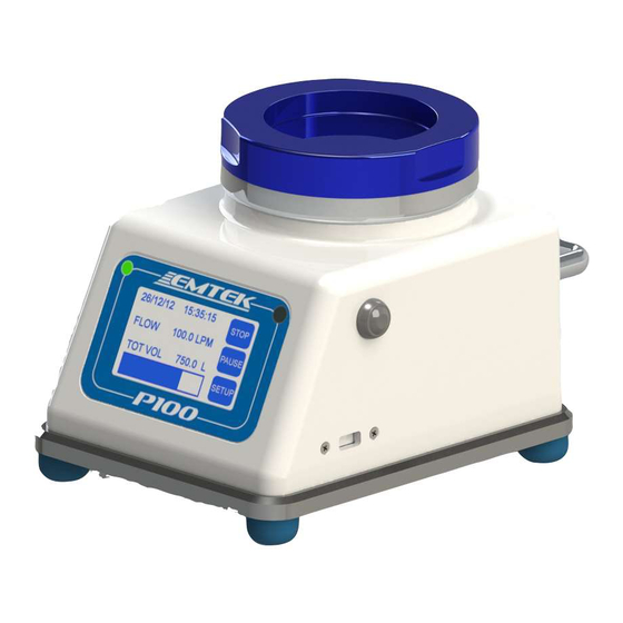
Section 5 P100 Description P100 Front View Fig 5.1.1 P100 Front/Side View 1. Inlet Cover (100 LPM Inlet Cover Shown-Blue, 28.3 is Clear) 2. Unit Power ON Indicator Green LED (Power On=Solid, Sample Run=Flashing) 3. IR Remote Receiving Sensor 4. LCD/ Touchscreen Interface 5. -
Page 22: P100 Rear View
P100 Rear View Fig 5.2.1 P100 Rear/Side View 100 LPM Inlet Cover-Blue Anodized (28.3 LPM Clear Anodized) Unit Power On/Off Pushbutton USB Port: Data Output to USB stick, firmware updates Exhaust Port: Allows for attachment of remote exhaust tubing KYDEX... -
Page 23: Quick Start Guide
NOTE: If the unit is not charged, plug the primary AC/DC power adapter cable into the power receptacle on the rear of the P100 (Fig 5.1.2, #8), and then attach to an appropriate AC power supply source that is 100-240 VAC, and 50/60 Hz. -
Page 24: Operating Instructions
Selecting the “” arrow moves the cursor backwords to clear/change previous entries Selecting “” or “” arrows, brings up the previous, or next keypad views. NOTE: If the touchscreen does not appear to be tracking properly, please follow the Touchscreen Calibration procedure described in section 7.6 P100 USERS MANUAL JUN2014v03... -
Page 25: Setup Screen (Main Menu)
UNIT INFO Unit Serial Number, Equipment Number, Firmware Version SAVE PRGM Save specific sampling programs, which include: Sample Flow Rate, selected or Set Volume, Delay/Test/Hold periods, Units for Flow and Volume P100 USERS MANUAL JUN2014v03... -
Page 26: Run Display
The RUN DISPLAY will then show the currently set collection parameters (e.g., for the next run), and display the START SAMPLE RUN key. KEYS: = Start Sample Run, = Stop Sample Run, =Pause Sample Run = Resume Sample Run , =Go to SETUP Screen P100 USERS MANUAL JUN2014v03... -
Page 27: Set Sample Parameters
Maximum Volume Allowed: @ 28.3 = 3396 L, @ 100 LPM = 3000 L, or 3 Cubic Meters VOLUME: Can be entered in 1, 2, 3, or 4 characters, from left to right. Example: 1_ _ _ , 10_ _, 100_, or 1000 liters. P100 USERS MANUAL JUN2014v03... - Page 28 FLOW UNITS = Pick from LOV: Liters Per Minute (LPM), or Cubic Feet/Minute (CFM) Line 6: VOL UNITS = Pick from LOV: Liters, Cubic Meters, or Cubic Feet (shown as L, CM, or CF on Run/Display Screen) P100 USERS MANUAL JUN2014v03...
-
Page 29: Printer
Line 2: SET IR CHANNEL= Set the IR remote channel 1-5, default of 1 (See section 7.3 for IR Remote operation) Line 3: Turn flow alarm ON or OFF. Flow alarm is a fixed +-5% set flow. P100 USERS MANUAL JUN2014v03... -
Page 30: Delay, Test, & Hold Settings
Example: For a 15 minute hold time, enter: 00:15:00 NOTE: To quickly ZERO out the time (00:00:00) for each parameter, simply select a single numeric character in the first entry field and hit return. This will ZERO out the time for that parameter. P100 USERS MANUAL JUN2014v03... -
Page 31: Site Descriptions
Maximum site descriptions based on screen size, which is 17 Characters to fit screen views. SITE ID Keypad Views/Entry NOTE: Create site names by using the available characters on the keypads. Hit return to save the site ID, or program, on the list of values. P100 USERS MANUAL JUN2014v03... -
Page 32: Date & Time Settings
12-Hour Time Base Example: For a time of 6:15pm, enter: 06:15:00, then “1” (for PM), for 6:15am, enter 06:15:00, then “0” (for AM) 24-Hour Time Base Example: For a time of 6:15pm, enter 18:15:00, for 6:15am, enter 06:15:00 P100 USERS MANUAL JUN2014v03... -
Page 33: Data Output (Printer & Usb)
General: DATA STORAGE The P100 will store up to 500 samples in it’s internal memory. A warning will occur at power up, which requires acknowledgement, when memory hits 450 samples. The CPU will delete oldest sample runs to add new ones once 500 samples has been stored in the memory, or will prevent new runs from being taken once 500 runs have been stored. - Page 34 Remove USB stick and transfer data to a PC. Data output is CSV format. The data will open in common spreadsheets, such as Microsoft Excel. The data cannot be modified and then saved on the P100 unit. Once the data is saved IMPORTANT NOTE: outside of the P100 system, the data integrity is not guaranteed by EMTEK.
-
Page 35: Calibration (Due & Notification)
NOTE: This alarm function is controlled by the unit Administrator. It can only be turned OFF if ADMIN OPTION control for the CAL DUE ALM is OFF (requires ADMIN ID and Password). Fig. 7.10.1.1 Fig. 7.10.1.2 P100 USERS MANUAL JUN2014v03... -
Page 36: Administrative (Admin & User)
ADMIN ID = EMTEK ADMIN PASSWORD = 12345_ NOTE IMPORTANTE: Chaque P100 est livré avec un compte admin temporaire initial. Ce compte permettra la création d'un compte d'administrateur par le client. Ce compte doit être supprimé une fois un nouveau compte administrateur a été établi. Le compte provisoire est le suivant:... - Page 37 Line 3: Del Admin = Delete the currently viewed ADMIN:. Example as Above: EMTEK Selecting this option brings up the following confirmation screen. Select “YES” or “NO”...
- Page 38 Line 3: Del User = Delete the currently viewed USER:. Example as Above: EMTEK Selecting this option brings up the following confirmation screen. Select “YES” or “NO”...
-
Page 39: Administrative Control Options
OFF (OFF=User, ON=Admin Only) NOTE: Once the options are set as desired, the P100 must be power cycled (Turned OFF then ON) to log out the ADMIN and lock these functions as set, otherwise the can still be modified (turned ON or OFF) by the user. - Page 40 Line 1: BACKLIGHT: Adjust brightness of screen up or down. Line 2: CONTRAST: Adjust character contrast to general screen brightness. Line 3: BUZZER: ON/OFF selection for Keypad “Beeps”, Flow Alarm, End of Run Alarm Line 4: VOLUME: Adjust volume of Alarm, Buzzer, Beeps (scaled 1-20). P100 USERS MANUAL JUN2014v03...
-
Page 41: Unit Information (Firmware Version)
7.1.12 UNIT INFO Screen View Unit Information Screen Options (view only) Firmware 1.083 View SERIAL NO. = Unit Serial number (5 Characters, assigned by EMTEK) Line 1/2: Line 3/4: EQUIP NO = Unit equipment number, if desired. (assigned by end user during calibration) Line 4/5: FIRMWARE = Current Firmware Version of unit (ex: 1.083) -
Page 42: Save (Sample) Programs (Select, Add, Delete)
NOTE: Create Program names by using the available characters on the keypads. Hit return to save the new program on the list of values. EXAMPLE PROGRAM: Name: IS08, Flow Rate: 100, Volume: 1000, Delay: 00:00:15, Units: Flow in LPM, Volume in L P100 USERS MANUAL JUN2014v03... - Page 43 DELETE PROGRAM: Delete the currently shown program under SAVED PROGRAMS. The following confirmation window will appear. Select “YES” or “NO” to delete or retain the program. NOTE: Assure that a “blank” program is retained, or created for ad hoc entries. P100 USERS MANUAL JUN2014v03...
-
Page 44: Ir Remote Control
Infrared Red (IR) Remote Control Fig 7.2.1 IR Remote Control Table 7.2.1 Functions of Remote Control Operation of 1 to 5 P100 Units Unit IR Button Name Description Setting # Sample On / Pause Initiate / Pause / Resume sample period Selected ... -
Page 45: Operating The P100 With The Remote Control
7.2.2 Operating the P100 with the Remote Control 1. Set the IR Channel on the P100 (under ALARM RMT) to the desired ID (1-5). (See Section 7.1.5) 2. To start the sampling period, press the Start key of the unit to be operated (1-5). -
Page 46: Alarms/ Warning Screens
7.3.2 P100 gets down to a set level during a sample run (13.5 V), the LOW BATTERY warning screen appears, the run is paused and the user is prompted to “ATTACH CHARGER TO CONTINUE”. If a power supply is attached within 60 seconds, the blower will restart and continue the sample. -
Page 47: Optional Thermal Printer Operation
7.4.1 Loading Printer Paper/Labels The P100 may be used with an optional thermal printer. The printer has the option for normal thermal paper operation or can be utilized with specified thermal labels. Important Note: To prevent damage to the print head, the printer should never be operated without paper/labels. - Page 48 NOTE: Select and use the “LABEL” setting for “ROLL TYPE” in the P100 Printer Settings. 6b. If paper, or label stock without backing is used, no specific label alignment is required.
- Page 49 Attach Ethernet Plug End to P100 Ethernet Port Attach RJ11 Connector End to P100 Printer Port & Pull Cable into Cable Pass Through Slot The printer batteries have to be partially charged to be able to run the unit while charging, if NOTE: desired.
-
Page 50: Hepa Filter & Battery Pack
2) Power on the P100 3) Fully discharge the P100. This is best achieved by entering a sample volume of “0”, and a flow rate of 100 LPM. This will run the battery down, without multiple interactions by the user. -
Page 51: Touch Screen Sensor Calibration
P100 for easy transport. The P100 inlet cover includes a locking mechanism to assure it will not fall off during transport. But, the user must assure it is locked in place before transporting the P100. Use the handle to transport between sampling locations, or facilities. If transporting the P100 outside of a controlled environment, it is ideal to place it within a clean or sterile transport bag, or supplied custom carrying case, to minimize potential contamination. -
Page 52: Network Operation Of The P100
The P100 is equipped with an Ethernet 10Base-T/100Base-T Port that will allow for an optional PC based software program to view or extract the Sample Run Data (Run Data), and/or operate the P100 units connected to the Ethernet. The Sample Run Data can be downloaded or viewed, but cannot be modified while within the units memory. -
Page 53: Appendix A P100 Sampler - General Sampling Procedure
The required plate height is set with the aid of the adjustable stage and media distance indicator on the inside top of the inlet lid. The required sample volume or time period is set on the P100 set up screen and the testing period is initiated. -
Page 54: Materials
Adhesive Tape Maintenance Inspection To assure appropriate operation of the P100 sampling assembly, prior to each days use, sampling personnel should inspect the unit for any obvious physical defect. This inspection shall include but not be limited to a visual inspection of the sample inlet cover inlet holes to assure that they are free of occlusions to assure proper sample flow. - Page 55 AC / DC n'est pas branché au cours de désinfection. Ne pas retirer les panneaux ou le capot de la P100 pour tenter une réparation. Contacter EMTEK, LLC ou autres membres du personnel d'entretien qualifié en cas de dysfonctionnement de l'appareil.
-
Page 56: P100 Sampler Assembly Set-Up And Testing
Perform the sanitization procedure in Appendix B. • The P100 must be calibrated as a system with the desired configuration (28.3 LPM (1CFM) or 100 LPM inlet cover). Both the 28.3 LPM and 100 LPM can be calibrated on each unit. - Page 57 1.4.4.1 With the inlet lid in place and no media on the stage, start the P100 and run the P100 for 1-2 minutes (see Section 7).
- Page 58 Fig A Starting the Testing Period: 1.6.1 From the RUN DISPLAY screen, press the Start button on the P100 or IR remote control to begin the test cycle. 1.6.2 If desired, the test period can be paused/resumed by pressing the pause/resume key on the P100 or IR remote control at any time during the testing period.
- Page 59 1.7.1 When the required volume is attained the blower motor automatically shuts off. If desired the test period can be terminated by pressing the Stop key on the P100, or on the IR remote. 1.7.2 If desired, the test period can be Pause/Resume by pressing the Pause/Resume key on the P100 or IR remote control at any time during the testing period.
- Page 60 If additional samples are to be taken at different locations in the same area on the same day, move the P100 sampler to the next location and repeat applicable portions of this procedure. If the unit is to be used in a different area on the same day (i.e., moved from one classified area to another) it is suggested to repeat applicable sanitization procedures in the next area prior to monitoring.
-
Page 61: Storage And Transport
P100 Horizontal Inlet (Optional) 3. A cover (e.g., sanitary cap, or bioshield) may be placed over the sample Inlet of the P100 during transport and storage to minimize the potential of contamination. 4. Store the P100 and associated components in a clean and dry place. -
Page 62: Appendix B Suggested P100 Sampler Sanitation
• Primary Disinfectants (e.g., Quaternary Ammonium Compounds) Important Note: Phenolic disinfectants should not be used on the P100 Enclosure, or touchscreen overlay, as it will cause the components to become very brittle in a short period of use. • Secondary Disinfectants (e.g., 70% 0.2µm filtered or sterilized alcohol) •... - Page 63 2. P100 Sanitization: 2.1 Before sanitizing the P100, insert the supplied Blower Inlet (Fig. 1), Ethernet port (Fig. 2), and USB port (Fig. 3) plugs, into the appropriate receptacles, as shown in the following images: FIG 1 - Blower Inlet Plug Placement...
- Page 64 P100 Inlet Cover, Inlet Base, and Media Stage Sanitization: Remove the P100 Inlet Cover 3.1.1 The P100 inlet cover may be autoclaved prior to each days testing if desired, or chemically sanitized. 3.1.2 For chemical sanitization of the P100 Inlet Cover, Inlet Base, and Media Stage, saturate a wipe with a primary disinfectant (e.g., Quaternary Ammonium Compound) and wipe all surfaces of...
-
Page 65: Appendix C Optional Sampling Components
• Remote Exhaust Kit (C.4) Compressed Air/Gas Sampling Kit The P100 may be used for Compressed Air/Gas system testing. This can be performed with the following components, supplied with the kit: EMTEK MICRO HPD (High pressure diffuser) A – Exhaust Filters B –... - Page 66 Using pre sanitized, or sterilized components, as described above, 1) Attach the inlet adapter (1) to the P100 pre sanitized or sterilized P100 inlet cover. Press the inlet Adapter down firmly and evenly, from the top of the inlet, until it seats with the P100 inlet cover.
-
Page 67: Horizontal Flow Inlet
For use: 5) Simply set the horizontal inlet on top of a sanitized P100 100 LPM, or 28.3 LPM inlet cover, with the O-ring evenly sitting at the rim of the opening. -
Page 68: Remote Sampling Inlet
The supplied tubing may be autoclaved as well. For use: 1) Simply set the inlet adapter on top of a sanitized P100 100 LPM, or 28.3 LPM inlet cover, with the O-ring evenly sitting at the rim of the opening in the inlet cover. -
Page 69: Remote Exhaust Kit
For use: 1) Simply thread the exhaust adapter into the exhaust port on the P100. This should be finger tight only. Tools shoot not be used, or needed, to attach, or detach the fitting. Note, the nut, retaining the tubing, can be threaded off first, and the male/male fitting can be attached to the exhaust port, and then the exhaust tubing/nut assembly can be threaded into the P100 adapter fitting. -
Page 70: Appendix D Suggested Sample Submission And Results Recording
Microbial Identification. Discard all other plates in an appropriate Bio-Hazard container for disposal. Test Report Forms, once completed, should be reviewed for accuracy and completeness, and signed by a second qualified analyst. P100 USERS MANUAL JUN2014v03... -
Page 71: Feller Calculation Tables
NOTE: If Feller Calculations are required by your procedures, a Feller table follows. Please use at your discretion. FELLER CALCULATION TABLE (1-100 CFU) Applies to P100 300 Hole inlet Covers: P100.INLT.28 (28.3 LPM/1 CFM) & P100.INLT.100 (100 LPM) Description Feller conversions are calculations performed, per the formula below, to allow for potential coincidence capture events, whereby more than one organism could potentially be drawn through the same inlet of the air sampler and be impacted, or captured, on the same location on the test plate. -
Page 72: Appendix 1 Ce Declaration Of Conformity
Appendix 1: CE Declaration of Conformity P100 USERS MANUAL JUN2014v03... -
Page 73: Appendix 2 Warranty
(5) Similarly, this warranty will be invalidated in instances where the malperformance is attributable to tampering or adjustment by other than factory approved personnel. (6) EMTEK’s Liability under the terms of this warranty is limited to repair or replacement of defective of products at no charge to the customer.
Need help?
Do you have a question about the P100 and is the answer not in the manual?
Questions and answers