Table of Contents
Advertisement
Designed and Manufactured in Australia by
Ampcontrol Pty Limited ACN 000 915 542
Phone: (02) 4956 5899
www.ampcontrol.com.au
USER MANUAL
VoiceCom System
User Manual
Fax: (02) 4956 5985
No copies of the information or drawings
within this manual shall be made without the
prior consent of Ampcontrol.
E06397 ISSUE 4 15/8/08
VCA_Manual_Issue_4_E06397_15/8/08.pdf
Advertisement
Table of Contents

Summary of Contents for Ampcontrol VCA
-
Page 1: User Manual
VoiceCom System User Manual Designed and Manufactured in Australia by No copies of the information or drawings Ampcontrol Pty Limited ACN 000 915 542 within this manual shall be made without the Phone: (02) 4956 5899 Fax: (02) 4956 5985 prior consent of Ampcontrol. - Page 2 Ampcontrol Pty Ltd, 250 Macquarie Road Warners Bay, NSW 2282, Australia. Disclaimer Ampcontrol Pty Ltd will make no warranties as to the contents of this documentation and specifically disclaims any implied warranties or fitness for any particular purpose.
-
Page 3: Table Of Contents
Navigation ..............................19 Voice Message Information Page – Level 1 ....................19 VCA Message Bank Download Page – Level 1 ..................20 Line Status, VAA Status and Programming Pages – Level 2 and 3 ............20 Line Status Page ............................20 VAA Address Setup Page .......................... - Page 4 VCA Configuration Record ......................... 61 APPENDIX B – MODBUS ............................. 63 Configuration .............................. 63 VCA Modbus Read and Write Functions ....................63 Initiating Voice Messages and Voice Message Control ................63 To initiate a voice message: ........................64 Stopping a voice message: ........................64 Message Queuing ............................
- Page 5 Voice Messages ............................72 Loading Voice Messages ........................... 72 APPENDIX D – MENU MAP ..........................73 APPENDIX E– PARTS LIST ..........................74 APPENDIX F – SPECIFICATIONS ........................75 VCA ................................75 Tones ................................. 75 APPENDIX G – I.S. APPROVALS ........................77 CONTENTS...
-
Page 6: Chapter 1 - Overview Of The Voicecom System
Dust and moisture protected microphone Connection for two external speakers Address, volume, microphone gain and charging current configurable at the VAA as well as at the VCA Compatible with most existing voice communication systems Applications ... -
Page 7: The Voicecom Controller - Vca
2-wire audio interface connection to connect the VoiceCom System to a telephone exchange via an approved barrier 8 inputs for the connection external keypad control buttons and a lock switch (or the VCA Remote Keypad Module) Figure 1 – VoiceCom system connection diagram... -
Page 8: Pc Software
VOICECOM USER MANUAL ISSUE 4 PC Software The Controller is supplied with the VCA Message Bank Editor Windows PC software. The software enables the user to create, edit and download voice message banks to the Controller. A separate PC program is required for the recording of individual voice message audio files before the voice message bank can be created. -
Page 9: Chapter 2 - Installation
VAA unit wiring can be found later in this manual. The VCA has eight terminal headers and is supplied with seven terminal plugs. The I.S. Earth terminal is the eighth header and is fixed to the rear of the VCA. There is also a mains earth connection point, which should not be confused with the I.S. -
Page 10: Digital Inputs
-V PS1 110Vac RELAY/PWR Figure 3 - VCA Connections Digital Inputs The controller has 14 digital inputs labelled DI1 to 12, PSR1 and PSR2. A 24VDC supply is required to assert these inputs. The negative side of this supply is connected to the 0V DI terminal. The positive side of the supply is applied to the digital input as required. - Page 11 VOICECOM USER MANUAL ISSUE 4 cannot NOTE: Pre-start alarms be initiated via Modbus. The PSR1 and PSR2 inputs must be used to initiate pre start alarms on Lines 1 and 2. Table 1 - Connections for Digital Input/Modbus Mode Terminal Function Momentarily apply +24VDC (edge triggered inputs) to play voice messages 1 to 12 DI1 to DI12...
-
Page 12: Digital Outputs
– asserted when a “Line Fault” occurs. Line Faults include faults such as the number of VAA communicating with the VCA being less than or greater than the number of VAAs online setting (VAA # Reply Alarm) or two or more VAA have the same address (VAA Address Clash). -
Page 13: Data Communication Ports
RS-232 – Message Bank Download The controller has two data ports. The RS-232 port is used to connect the VCA to a PC for the downloading of the Voice Message Bank. The Voice Message Bank is a single file that contains all of the pre-recorded voice messages. - Page 14 VOICECOM USER MANUAL ISSUE 4 Note: The output parameters of the I.S supply must match the input parameters of the VCA and the VAA. Refer to VCA Certificate of Conformity AUS Ex 03.3880X and VAA Certificate of Conformity Aus Ex 03.3881X for input parameters.
-
Page 15: I.s. Keypad Interface
Interface Terminals – Figure 6 - I.S. keypad interface wiring to VCA Remote Keypad Module (E08985) NOTE: The I.S. power supply connected to LINE 1 or LINE 2 can be used to for the VCA I.S. Keypad Interface. -13-... -
Page 16: I.s. Audio Interface
I.S. Earth The intrinsically safe earth terminals are used to connect the VCA to a local intrinsically safe earth. The I.S. earth should be a direct connection and should not be shared with other devises. A minimum of two 4mm cores should be used. -
Page 17: Vaa Physical Installation
VOICECOM USER MANUAL ISSUE 4 VAA Physical Installation The VAA comes in its own stainless steel enclosure. The VAA stainless steel IP66 enclosure includes two speakers and gland entries (p/n E09100). Other entry configurations can be accommodated. The VAA is also available as a panel mountable module (p/n E08831) for installation into an existing enclosure or panel door, shown in Figure 8. -
Page 18: Vaa Connections And Wiring
VOICECOM USER MANUAL ISSUE 4 VAA Connections and Wiring The VAA module has three connection headers, as shown in Figure 9 below: 0Volts Audio Call -Vline Figure 9 - VAA headers and communication line and speaker wiring VoiceCom communication line (4-way) Speakers (4-way) Battery pack (10-way) The communication line connections are listed in table 9 and speaker connections are listed in table 10 below. -
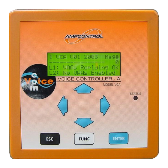
Page 19: Chapter 3 - Vca Operation
CHAPTER 3 - VCA Operation The VoiceCom Controller version A, or VCA, as its name suggests, is the master controller of the VoiceCom system. From the VCA, the VoiceCom system can be easily configured and interrogated. It controls the operation of the pre- start alarm and it stores and plays pre-recorded audio messages. -
Page 20: Display And Main Menu Page
Pre-Start Alarm Operation chapter for more information on the operation of the pre-start alarm. There are also a couple of VCA fault message that can appear on the second line of the display on the Main Menu page. Refer to the Troubleshooting chapter for more information on VCA faults. -
Page 21: Menu System
Menu System The VCA menu system consists of six menu levels. The menu level number is displayed in the top left corner of all VCA pages, except for the Voice Message Information page. Each menu level may contain one or a number of pages. -
Page 22: Vca Message Bank Download Page - Level 1
VCA Message Bank Download Page – Level 1 This page shows the PC to VCA communication and Message Bank download status when the VCA is connected to a PC running the Voice Message Bank Editor program. The display needs to be put on this page in order to download a voice message bank. -
Page 23: Vaa Address Setup Page
Polling Address Number While the digital communication protocol is running, the VCA does a ‘round-robin’ scan of every VAA address, 1 to 31. This takes approximately 7 seconds. This number shows which address is currently being scanned and will count rapidly up through the address range. - Page 24 VAA addressing procedure 1. From the VCA’s Main Status page, arrow down to the Line Status page for the line that the VAA unit is connected to (LINE 1 or LINE 2). Note from the menu structure diagram that the first page below the Main Status page is the Line 1 Status page.
-
Page 25: Vaa Status Pages
VAA unit online at that particular address. A more detail description of this page and the other menu pages can be found in the VCA Operation chapter of this manual. A C symbol indicates an address clash. Two or more VAAs may have been programmed with the same address. -
Page 26: Vaa Operational Status Values
VOICECOM USER MANUAL ISSUE 4 The VAA Status pages show the current operational status and programmable settings for each VAA connected to the line. Figure 20 shows the status page for a VAA with serial number 00100 on Line 1, programmed to address 1. 2 L1 VAA# 1 Sn00100/ Vline:16.0V Thr:[ 3] V bat: 6.6V Vol:[L3]... -
Page 27: Setting Vaa Parameters
VOICECOM USER MANUAL ISSUE 4 Volume and Microphone Gain The volume and microphone gain are combined into one setting, for example “L3” where L is the gain level and 3 is the volume level. The volume setting controls the VAA unit’s output volume. The volume can be set to a value from 0 to 3 where 3 is the maximum volume. -
Page 28: Modbus Communication Status - Level 4
Modbus Communication Status – Level 4 The Modbus page is the only menu page on menu level 4, shown in Figure 22. It displays the VCA’s Modbus communication status. Modbus is the protocol used on the VCA’s RS-485 port to communicate with Modbus capable control systems such as PLCs. -
Page 29: Relay Outputs And Digital I/O - Level 5
VOICECOM USER MANUAL ISSUE 4 Relay Outputs and Digital I/O – Level 5 The three pages on this menu level show the current state of the VCA’s four relays, four digital outputs and fourteen digital inputs. These pages are useful for fault finding. -
Page 30: Digital Inputs Page
: The number of VAAs the VCA can communicate with does not match the number of VAAs meant to be online. The VAAs online setting is one of the Configuration pages found on menu level 6. More information on this setting can be found later in this chapter. -
Page 31: Vca Configuration - Level 6
VCA Configuration – Level 6 This is the final level of the VCA menu structure. All the user configurable system and line specific settings are found on this level. Most of these are set during commissioning. Refer to Appendix A for VoiceCom system commissioning recommendations. - Page 32 This is the number of VAA’s that are VAA’s to be connected to the LINE 2. This is the number Online of VAAs that the VCA should be able to communicate with. If no VAAs are connected, then this is set to None.
- Page 33 VOICECOM USER MANUAL ISSUE 4 Message Bank [ 28k8bps] This sets the baud rate of the VCA to PC Serial Baud Rate connection using the RS-232 port for the [ 57k6bps] downloading of Message Banks. All other [115k2bps] communication parameters are fixed as the...
-
Page 34: Changing Vca Settings
VOICECOM USER MANUAL ISSUE 4 Changing VCA Settings The procedure for changing a setting on menu level 6 is the same for all settings. The procedure explains how to change VCA configuration settings using the Voice Message Playback Volume setting as an example. -
Page 35: Chapter 4 - Vaa Operation
VOICECOM USER MANUAL ISSUE 4 CHAPTER 4 – VAA Operation The VoiceCom Amplifier version A, or VAA, is the field communications unit of the VoiceCom system. It consists of two parts: 1. VAA amplifier module 2. VAA battery pack NOTE: The battery pack must be connected to the VAA amplifier module in order for the VAA to function. Figure 26 - Amplifier Module with Battery Pack VAA Amplifier Module VAA Features... -
Page 36: The Lcd
VOICECOM USER MANUAL ISSUE 4 Figure 27 - VAA Amplifier Module Front and Back The LCD L-U 12.0 VAA operational parameters (cycles between Digital comms heartbeat status indicator bar L-U = line volts, B-U = battery volts and B-I = battery current) Amplifier on status indicator bar VAA data polling indicator bar... -
Page 37: Display Messages
VAA is programmed to that address or not. Every time a VAA is polled this segment will flash. Viewing a VAA’s status page from the VCA will cause that VAA to be polled more often. -
Page 38: Vaa Setup Mode
VAA Setup Mode The VAA Setup Mode allows the VAA’s user programmable settings to be changed locally at the VAA unit. The VCA Operation chapter describes how to program all VAA settings from the VCA. Being able to program these settings from the VAA means that a VAA can be correctly set up when it is connected to the communication line, without needing to go to the VCA. -
Page 39: Enter Setup Mode
VOICECOM USER MANUAL ISSUE 4 VAA operating mode Local volume Threshold Battery charging current VAA address Enter Setup Mode A special key sequence is required to enter the VAA setup mode. Some practice may be required. To enter Setup mode follow the procedure below: Press and hold the VAA’s SPEAK and FUNC buttons at the same time. -
Page 40: Vaa Battery Pack
Description VAA Mode VCA or --- If connected to a VoiceCom system this setting should be set to VCA. If set to --- the VAA will not respond to VCA digital communication polling and will not appear online. Volume/Gain L0 to L3 and H0 to The L/H sets the sensitivity level and the number, 0 to 3, sets the volume level. -
Page 41: Removing And Connecting Battery Pack From Amplifier Module
VOICECOM USER MANUAL ISSUE 4 Removing and Connecting Battery Pack from Amplifier Module Removing 1. Unscrew the two captive, allen head battery pack retaining screws using a 2.5mm hex head tool. 2. Gently pull the battery pack away from the amplifier module at the 10-way connector to disconnect the battery pack. -
Page 42: Auto-Shutoff
VOICECOM USER MANUAL ISSUE 4 Auto-shutoff If the battery voltage falls below 5.9V, it will shut down its output to prevent causing permanent damage to the SLA battery cells. This will occur if there is insufficient charging current available from the communication line. Sleep Mode The battery pack can be put to ‘sleep’... -
Page 43: Chapter 5 - Pre-Start Alarm Operation
4. The pre-start alarm will sound for as long as the respective digital input is held high. It sounded be sounded for at least 6 seconds, which is the time it can take for the VAAs to confirm sounding the alarm. The VCA will allow a pre-start alarm to sound for a maximum of 30 seconds. -
Page 44: Verifying The Pre-Start Alarm Request Input
1. All connected VAAs will receive the pre-start command and necessary parameters from the VCA. 2. The alarm tones are generated locally by each VAA, not by VCA. The tone sounded depends on the pre-start tone set for that line at the VCA. -
Page 45: Pre-Start Alarm Confirmation
3. When the VCA receives the confirmations from all or most of the VAAs, the o turns to either an X or a P. The P indicating that that VAA has confirmed sound the alarm and the X indicating that it has not. This display remains while the pre-start input is asserted. -
Page 46: Verifying The Pre-Start Alarm Later
VOICECOM USER MANUAL ISSUE 4 Line Status page showing 20 VAAs on LINE 1, at 2 Line 1 [20] VAA’s addresses 1 to 20, before the pre-start is initiated. PSW RQo/o OPo/o █ █ █ █ █ █ █ █ █ █ █ █ █ █ █ ----- ----- - █... -
Page 47: Pre-Start Alarm Operation Examples
VOICECOM USER MANUAL ISSUE 4 Pre-start Alarm Operation Examples Example 1 – a successful pre-start alarm The system: 2 Line 1 [20] VAA’s VAAs connected: 20 PSW RQo/o OPo/o # of VAA’s to be online: 20 █ █ █ █ █ █ █ █ █ █ █ █ █ █ █ ... -
Page 48: Example 3
VOICECOM USER MANUAL ISSUE 4 Example 3 The system: VAAs connected: 20 # of VAA’s to be online: 20 ServiceFactor # VAA’s offline: 3 1. For this example the Service Factor is set to 3. 2. Figure 34 shows how the Line Status page once all the 2 Line 1 [20] VAA’s confirmations have been received. -
Page 49: Chapter 6 - Creating And Downloading Voice Messages
VCA Message Bank Editor The next step is to build the voice message bank. This is done using the VoiceCom VCA Message Bank Editor PC software provided with the VCA Controller. The VCA Message Bank Editor is a software program for Windows PCs. -
Page 50: Creating A Message Bank
Starting the Editor 1. To start the editor, double click on the VCA Message Bank Editor executable file. A title window will appear for a moment showing the software version number as the program starts up. The main editor window, as shown in Figure 36, will appear. - Page 51 VOICECOM USER MANUAL ISSUE 4 2. Like many Windows operations, one process can be done more than one way. Adding an audio message to the Voice Message can be done by either: a. Selecting the message number where you would like to add a message by clicking the message number once.
- Page 52 The lowest setting, 8bit uLaw 11kHz, is comparable to AM radio quality audio. The format chosen has a direct impact on the Voice Message Bank memory used. The higher the audio quality, the larger more memory used. The VCA Voice Message Bank memory is approximately 16MBytes. For -50-...
- Page 53 Lowering the audio quality makes the audio message smaller, thus saving memory. This process only affects how the message is played by the VCA. The original audio format of an imported audio file is not lost and can be restored at any time by opening the Format menu and choosing the highest resolution and sample rate.
-
Page 54: Downloading And Uploading The Message Bank
Once a Message Bank has been created or modified, the next step is to download it to the VCA. However, a Message Bank that has been loaded into a VCA can up uploaded back to a PC. This may be necessary if the original Message Bank PC file has been lost and voice messages need to be added or changed, for example. - Page 55 Figure 40. 7. The Port selection sets the serial COM port on the PC used to connect to the VCA. Most PCs usually have one or two serial COM ports and they should be labelled. If the PC only has one COM port, this port is usually referred to as COM 1.
-
Page 56: Uploading
Uploading The procedure for uploading a Message Bank from the VCA to a PC is almost the same as the one for downloading. Follow steps 1 to 10 as described for downloading a Message Bank. Once communication has been established follow the procedure below: 1. -
Page 57: Chapter 7 - Troubleshooting
Faulty VAA unit Isolate individual unit and replace Poor\Faulty wiring* See notes. Constant digital noise on Adjust VCA settings to turn digital comms line VCA has incorrect settings off with audio Thresholds on VAA units to Adjust threshold settings on the VAA units... - Page 58 Battery Replace Battery Clicking sound when speak button pushed Replace VAA VAA setting is not in correct Adjust settings at VAA mode (VCA or DAC) VAA unit not showing as Battery Replace Battery ‘on line’ at VCA Replace VAA -56-...
-
Page 59: Appendix A - Commissioning
VAAs are replaced and easily accessible. NOTE: The location of the VCA has no effect on VAA addressing. The VCA could be connected to a point half way along the communication line, at the tripper drive for example. This is shown in Figure 45. -
Page 60: Volume, Microphone Gain And Audio Threshold
Volume, Microphone Gain and Audio Threshold The procedure for configuring these settings can be found in the VCA Operation chapter, under the section VAA User Programmable Settings. These settings can also be adjusted at the VAA. The procedure for changing settings at the VAA can be found in the VAA Operation chapter, under the section VAA Setup Mode. -
Page 61: Vca Line Configuration
LINE 1 is set to 3. This means that up to three VAAs can fail to sound a pre-start alarm and the pre-start alarm on LINE 1 to be successful. The VCA will close its PSC 1 (for LINE 1) relay, the pre-start confirmation permissive. If four VAAs fail to send confirmation of sounding a pre-start alarm, pre-start alarm has failed to sound as intended and the PSC 1 relay will not close. -
Page 62: Pre-Start Warning Tone
Specifications section of this manual. Use the following form to note down all the commissioned VCA configuration settings and keep this form in safe place. This record will save time if the VCA is replaced. -
Page 63: Vca Configuration Record
VOICECOM USER MANUAL ISSUE 4 VCA Configuration Record Tick the box matching setting value or write setting value in the square brackets [ ] provided. Keep a copy of this record near the VCA. Setting Range Value Voice Message Mode ... - Page 64 VOICECOM USER MANUAL ISSUE 4 Modbus Communication Slave [ 1] to [31] Address Message Bank Serial Baud [ 28k8bps] Rate [ 57k6bps] [115k2bps] [230k4bps] -62-...
-
Page 65: Appendix B - Modbus
The VCA is equipped with an RS-485 communication port that allows point-to-point or multi-drop connection to a control or SCADA system. The protocol used by the VCA is Modbus RTU. Refer to the Installation and Wiring chapter of this manual for more information on wiring the VCA’s RS-485 port. -
Page 66: To Initiate A Voice Message
Writing 0 (zero) to address 0 (zero) will cancel the voice message currently playing. Message Queuing The VCA can queue one message while another is playing. For example, while message 20 is playing, message 100 can be written to Modbus address 0 (zero). Message 20 will play to completion, immediately followed by message 100. - Page 67 VOICECOM USER MANUAL ISSUE 4 This data has been divided into two Data Banks: Bank 0 (zero) and Bank 1. Each bank contains four bytes of data. These banks are: Byte Bank 0 Bank 1 Line Voltage Volume Battery Voltage Threshold Battery Current VAA Serial Number High Byte...
-
Page 68: Appendix C - Application Notes
Create Message Bank on other PC and save on networked file server. Have Message Bank Editor program loaded on local PC. Run Message Bank Editor and download Message Bank. Connect VCA via serial to Ethernet converter and load Message Bank from networked PC using “serial port replicator” s/w or h/w. -
Page 69: Appendix D - Menu Map
VOICECOM USER MANUAL ISSUE 4 APPENDIX D – Menu Map LEVEL 1 MAIN MENU AUDIO MSG MSG BANK MAIN PAGE INFORMATION DOWNLOAD LEVEL 2 LINE 1 STATUS VAA ADR 1 VAA ADR 31 … LINE 1 STATUS STATUS ENTE ENTE VAA ADR VAA CHARGE VAA VOLUME &... -
Page 70: Appendix E- Parts List
E08588 E08985 VCA Remote Keypad E09441 VoiceCom Audio Barrier (type NB8.5AC) E09100 VAA Stainless Steel Speaker Enclosure with Gland Entries E08831 VAA + Battery pack E08584 VAA Battery Pack E9400 RS-232 VCA to PC message bank download serial cable -74-... -
Page 71: Appendix F - Specifications
250 VAC max - Relay Current Rating Digital Communications - Communication Ports RS-232, RS-485 - RS-232 protocols PC to VCA for Voice Message download only - RS-232 baud rates 28.8Kbps, 57.6Kbps, 115.2Kbps, 230.4Kbps - RS-485 protocols Modbus RTU - RS-485 baud rates/parities 1200, 2400, 4800, 9600, 19.2Kbps / even, odd, none... - Page 72 VOICECOM USER MANUAL ISSUE 4 508, 724, 1016 1563, 1563 1016, 724, 508 1563, 1563 508, 508, 508 1563, 1563 1250,742, 1250 1563, 1563 508, 724, 1016 1563, 1563 508, 724, 1016 1563, 1563 508, 724, 1016 1563, 1563 No tones 1563, 1563 508, 724, 1016 No tones...
- Page 73 VOICECOM USER MANUAL ISSUE 4 APPENDIX G – I.S. Approvals -77-...
- Page 74 VOICECOM USER MANUAL ISSUE 4 -78-...
- Page 75 VOICECOM USER MANUAL ISSUE 4 -79-...
- Page 76 VOICECOM USER MANUAL ISSUE 4 -80-...
- Page 77 VOICECOM USER MANUAL ISSUE 4 -81-...
- Page 78 VOICECOM USER MANUAL ISSUE 4 -82-...
-
Page 79: Appendix G - I.s. Approvals
VOICECOM USER MANUAL ISSUE 4 -83-... - Page 80 VOICECOM USER MANUAL ISSUE 4 -84-...
- Page 81 VOICECOM USER MANUAL ISSUE 4 -85-...
Need help?
Do you have a question about the VCA and is the answer not in the manual?
Questions and answers