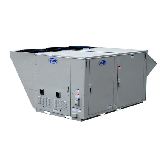
AAON RN SERIES Installation Operation & Maintenance
Horizontal packaged rooftop units, heat pumps,
& outdoor air handling units
Hide thumbs
Also See for RN SERIES:
- Installation operation & maintenance (136 pages) ,
- Installation, operation & maintanance manual (116 pages) ,
- Installation operation & maintenance (108 pages)
Table of Contents
Advertisement
Horizontal Packaged Rooftop Units, Heat Pumps,
Installation, Operation,
WARNING
FIRE OR EXPLOSION HAZARD
Failure to follow safety warnings
exactly could result in serious
injury, death or property damage.
Be sure to read and understand
the installation, operation, and
service instructions in this manual.
Improper installation, adjustment,
alteration, service, or maintenance
can cause serious injury, death, or
property damage.
A copy of this IOM should be kept
with the unit.
& Outdoor Air Handling Units
& Maintenance
o Do not store gasoline or other flammable
vapors and liquids in the vicinity of this or any
other appliance
o WHAT TO DO IF YOU SMELL GAS
Do not try to light any appliance.
Do not touch any electrical switch; do not
Leave the building immediately.
Immediately call your gas supplier from a
If you cannot reach your gas supplier, call
o Startup and service must be performed by a
Factory Trained Service Technician.
RN SERIES
WARNING
use any phone in your building.
phone remote from the building. Follow the
gas supplier's instructions.
the fire department.
Advertisement
Table of Contents

Related Manuals for AAON RN SERIES


Summary of Contents for AAON RN SERIES
- Page 1 RN SERIES Horizontal Packaged Rooftop Units, Heat Pumps, & Outdoor Air Handling Units Installation, Operation, & Maintenance WARNING WARNING o Do not store gasoline or other flammable FIRE OR EXPLOSION HAZARD vapors and liquids in the vicinity of this or any...
-
Page 3: Table Of Contents
Table of Contents Safety .............................. 8 RN Series Feature String Nomenclature ........Error! Bookmark not defined. General Information ........................24 Codes and Ordinances ......................24 Receiving Unit .......................... 25 Packaged Direct Expansion (DX) Units ................... 26 Gas or Electric Heating ......................27 Wiring Diagrams ........................ - Page 4 Replacement Parts ........................92 Appendix A - Heat Exchanger Corrosion Resistance ..............93 Appendix B - Thermistor Temperature vs. Resistance Values ............. 95 RN Series Startup Form ........................ 96 Maintenance Log ........................100 Literature Change History......................101 V76270 · Rev. A · 170727...
- Page 5 Table 24 - RN Series 11, 13, 16-25 and 30 ton Unit Filters ............91 Table 25 - RN Series 11, 13, 16-25 and 30 ton Energy Recovery Wheel Filters ......91 Table 26 - RN Series 11, 13, 16-25 and 30 ton Final Filters ............91...
- Page 6 Figure 2 - RN Series C Cabinet, ....................29 Figure 3 - Forklifting an RN Series A, B and C Cabinet, 11, 13 and 16-30 ton tons ....31 Figure 4 - Lifting Details of a 11, 13 and 16-30 ton tons ton Standard or Power Exhaust Unit .. 32 Figure 5 - Lifting Details of a 11, 13 and 16-30 ton tons Energy Recovery Wheel or Power Return Unit............................
- Page 7 ® AAON RN Series Horizontal Configuration Features and Options Introduction Energy Efficiency Installation and Maintenance Direct Drive Backward Curved Plenum Clogged Filter Switch Supply Fans Color Coded Wiring Diagram Variable Capacity R-410A Scroll Compressors in Isolated Compartment ...
-
Page 8: Safety
Safety Attention should be paid to the following statements: NOTE - Notes are intended to clarify the unit installation, operation, and maintenance. CAUTION - Caution statements are given to prevent actions that may result in equipment damage, property damage, or personal injury. WARNING - Warning statements are given to prevent actions that could result in equipment damage, property damage, personal injury or death. - Page 9 WARNING WARNING FIRE, EXPLOSION OR CARBON ROTATING COMPONENTS MONOXIDE POISONING HAZARD Unit contains fans with moving parts Failure to replace proper controls that can cause serious injury. Do not could result in fire, explosion, or open door containing fans until the carbon monoxide poisoning.
- Page 10 CAUTION CAUTION Electric motor over-current protection Rotation must be checked on all and overload protection may be a MOTORS AND COMPRESSORS of function of the Variable Frequency 3 phase units at startup by a qualified Drive to which the motors are wired. service technician.
- Page 11 CAUTION Failure of the condenser as a result of chemical corrosion is excluded Do not clean DX refrigerant coils with from coverage under AAON Inc. hot water or steam. The use of hot warranties and the heat exchanger manufacturer’s warranties.
- Page 12 (ESP) as specified on the unit from coverage under AAON nameplate. warranties and the heat exchanger manufacturer warranties. 6. The supply and return air ducts must be derived from the same space. It is...
-
Page 13: Rn Series Feature String Nomenclature
RN Series Feature String Nomenclature 0 - 3 - A A A 0 2 - B 0 1 B 0 : 0 1 - D Q 0 J - E 0 0 - 0 0 0 0 - 0 0 0 0 - D A - A 0 A A - A 0... - Page 14 RN Series Feature String Nomenclature RN A - 11 - C 0 - 3 - A A A 0 2 - B 0 1 B 0 : 0 1 - D Q 0 J - E 0 0 - 0 0 0 0 - 0 0 0 0 - D A - A 0 A A - A 0...
- Page 15 RN Series Feature String Nomenclature RN A - 11 - C 0 - 3 - A A A 0 2 - B 0 1 B 0 : 0 1 - D Q 0 J - E 0 0 - 0 0 0 0 - 0 0 0 0 - D A - A 0 A A - A 0...
- Page 16 RN Series Feature String Nomenclature RN A - 11 - C 0 - 3 - A A A 0 2 - B 0 1 B 0 : 0 1 - D Q 0 J - E 0 0 - 0 0 0 0 - 0 0 0 0 - D A - A 0 A A - A 0...
- Page 17 RN Series Feature String Nomenclature RN A - 11 - C 0 - 3 - A A A 0 2 - B 0 1 B 0 : 0 1 - D Q 0 J - E 0 0 - 0 0 0 0 - 0 0 0 0 - D A - A 0 A A - A 0...
- Page 18 RN Series Feature String Nomenclature RN A - 11 - C 0 - 3 - A A A 0 2 - B 0 1 B 0 : 0 1 - D Q 0 J - E 0 0 - 0 0 0 0 - 0 0 0 0 - D A - A 0 A A - A 0...
- Page 19 RN Series Feature String Nomenclature RN A - 11 - C 0 - 3 - A A A 0 2 - B 0 1 B 0 : 0 1 - D Q 0 J - E 0 0 - 0 0 0 0 - 0 0 0 0 - D A - A 0 A A - A 0...
- Page 20 RN Series Feature String Nomenclature RN A - 11 - C 0 - 3 - A A A 0 2 - B 0 1 B 0 : 0 1 - D Q 0 J - E 0 0 - 0 0 0 0 - 0 0 0 0 - D A - A 0 A A - A 0...
- Page 21 RN Series Feature String Nomenclature RN A - 11 - C 0 - 3 - A A A 0 2 - B 0 1 B 0 : 0 1 - D Q 0 J - E 0 0 - 0 0 0 0 - 0 0 0 0 - D A - A 0 A A - A 0...
- Page 22 RN Series Feature String Nomenclature RN A - 11 - C 0 - 3 - A A A 0 2 - B 0 1 B 0 : 0 1 - D Q 0 J - E 0 0 - 0 0 0 0 - 0 0 0 0 - D A - A 0 A A - A 0...
- Page 23 L = Option B + D B = Premium AAON Gray Paint Exterior Paint M = Option B + E C = Premium AAON Gray Paint Exterior Paint + R = Option A + B + D Interior Corrosion Protection...
-
Page 24: General Information
Codes and Ordinances RN Series units have been tested and Certification of Gas Heat Models certified, by ETL, in accordance with UL a. AAON heat... -
Page 25: Receiving Unit
Installation of RN Series units must conform transit. If damage is found it should be noted to the ICC standards of the International on the carrier’s freight bill. A request for inspection by carrier’s agent should be made Mechanical Code, the International Building Code, and local building, plumbing and in writing at once. -
Page 26: Packaged Direct Expansion (Dx) Units
The warranty card must be completed in full CAUTION and returned to AAON not more than 3 months after unit is delivered. CRANKCASE HEATER OPERATION Storage If installation will not occur immediately Some units equipped with following delivery, store equipment in a dry... -
Page 27: Gas Or Electric Heating
concentration builds up, oil is washed out of cooling mode or off. Do not leave part of the the compressor, leaving it starved for units switched to the opposite mode. lubrication. Cooling only units should be switched off at the thermostat during the heating season. The compressor life will be seriously shorted by reduced lubrication and the Gas or Electric Heating... -
Page 28: Wiring Diagrams
90.1 Wiring Diagrams Installation Unit specific wiring diagrams are laminated and affixed inside the controls compartment AAON equipment has been designed for door. quick and easy installation. Condensate Drain Pan Locating Units Unit requires drain traps to be connected to The curb should be mounted first and must the condensate drain pan of the unit. -
Page 29: Setting The Curb
The National Gas and Propane Installation Code, B149.1 specifies a 6 ft. horizontal Figure 2 - RN Series C Cabinet, vent terminal clearance to gas and electric 11, 13, 16-25 and 30 meters and relief devices. - Page 30 CAUTION All roofing work should be performed by competent roofing contractors to avoid any possible leakage. CAUTION Where the supply or warm air duct passes through a combustible roof, a clearance inch must maintained between outside edges of the duct and combustible material in accordance with National Fire Protection Association Standard 90A.
-
Page 31: Forklifting The Unit (11, 13 And 16-30 Ton)
(right) side. Forks Figure 3 - Forklifting an RN Series A, B and C Cabinet, 11, 13 and 16-30 ton tons It is recommended to lift the unit with the Lifting the Unit... -
Page 32: Figure 4 - Lifting Details Of A 11, 13 And 16-30 Ton Tons Ton Standard Or Power Exhaust Unit
Before lifting unit, be sure that all shipping Carefully lower and align the unit with material has been removed from unit. Secure utility and duct openings. Lower the unit hooks and cables at all lifting points / lugs until the unit skirt fits around the curb. Some provided on the unit. -
Page 33: Duct Connection
Duct Connection There to be a minimum of a 12” straight duct off of the supply duct with no size reduction and then a limitation of no more than a 45⁰ transition for the next 24”, this is to insure proper performance of the heaters. Air quantity and temperature stagnation could still be effected depending on how branch take-offs are taken off the main... -
Page 34: Figure 6 - Duct Connection
Figure 6 - Duct Connection... -
Page 35: Outside Air Rain Hood
Outside Air Rain Hood Rain hood must be opened before startup of the unit. Fresh air intake adjustments should be made according to building ventilation of local code requirements. 11, 13 and 16-30 ton Units Remove the two screws at the bottom of the rain hood that secure it in the shipping position. -
Page 36: Metal Mesh Filters (11, 13 And 16-30 Ton)
Metal Mesh Filters (11, 13 and 16-30 ton) Metal mesh outside air filters require installation of the filter rack on the intake of the rain hood. Clips which hold the metal mesh filters in the filter rack should face outward. Figure 9 - Rain Hood with Metal Mesh Filter Rack Installation Electrical WARNING... -
Page 37: Figure 10 - Unit Utility Entry
Route power and control wiring, separately, Size supply conductors based on the unit through the utility entry in the base of the MCA rating. Supply conductors must be unit. Do not run power and control signal rated a minimum of 75°C. wires in the same conduit. -
Page 38: Thermostat Control Wiring
Three phase voltage imbalance will cause CAUTION motor overheating and premature failure. The maximum allowable imbalance is 5%. Scroll compressors are directional and will be damaged by operation in Voltage imbalance is defined as 100 times the wrong direction. Low pressure the maximum deviation from the average switches on compressors have been voltage divided by the average voltage. -
Page 39: Gas Heating
Table 3 - Control Wiring Gas Heating Wire Size (Stranded) Total Wire Distance WARNING - Copper Conductors Allowable Only FOR YOUR SAFETY 20 AWG 200 ft 18 AWG 350 ft Read entire heating 16 AWG 500 ft installation section of this manual 14 AWG 750 ft before beginning installation of the... -
Page 40: Table 5 - Natural Gas (Ft 3 /Hr) Maximum Piping Capacities
Unit nameplate input rate value has been calculated at the altitude where the unit was Figure 12 - RN Series Gas Heat Exchanger shipped. Above 2,000 ft the input rate is adjusted 4% for every 1,000 ft. Table 5 - Natural Gas (ft /hr) Maximum Piping Capacities Specific Gravity = 0.6, Supply Pressure ≤... -
Page 41: Piping Sizing Examples
Piping Sizing Examples CAUTION A 100 ft pipe run is needed for a 1080 MBH natural gas heater. The natural gas has a Heater should be disconnected from rating of 1000 Btu/ft and a specific gravity the gas supply piping during pressure of 0.6 (Obtain these values from the local testing of the supply piping system gas supplier.) -
Page 42: Additional Gas Piping Considerations
Additional Gas Piping Considerations Installation Code CSA B149.1 or B149.2, Local codes will usually require a field the International Building Code, and any provided and installed manual main shutoff applicable local and regional codes and valve and union external to the unit. Main regulations. -
Page 43: Leak Testing
Leak Testing However, trace amounts may remain. When All components of gas supply system, performing the initial startup at the jobsite, it including manual shut off valves and the is highly recommended that people or any piping in the interior of the unit, should be other living animals, which may be sensitive leak tested with a soap solution before to the residual odors or gases, NOT be... -
Page 44: Open Loop Applications
Failure of the condenser as a result of chemical corrosion excluded from WATER-SOURCE HEAT coverage under AAON warranties and the PUMP APPLICATIONS heat exchanger manufacturer warranties. Water-source heat pump units using Failure of the condenser will allow water to 100% outside air must have electric... -
Page 45: Freezing Water In The Heat Exchanger
AAON warranties and the components. heat exchanger manufacturer warranties. Unit is capable of operating with Entering Water Temperatures (EWT) as low as 57°F,... -
Page 46: Table 9 - Standard Brazed Plate Heat Exchanger Water Connections
and limit bend radiuses to maintain balance WARNING in the system. Balancing valves, permanent thermometers and gauges may be required. WATER PRESSURE Before connection to the unit the condenser Prior to connection of condensing water system should be flushed to remove water supply, verify water pressure is foreign material that could cause condenser less than maximum pressure shown... - Page 47 CAUTION CAUTION PVC (Polyvinyl Chloride) and CPVC Installing contractor is responsible for (Chlorinated Polyvinyl Chloride) are properly sizing and installing water vulnerable attack certain system components. Improper fluid chemicals. Polyolester (POE) oils flow valves, piping, used with R-410A other improper pump operation may result refrigerants, even in trace amounts, in unacceptable unit operation and in a PVC or CPVC piping system will...
-
Page 48: Condensate Drain Piping
Condensate drain trapping and piping should Condensate Drain Piping 11, 13, 16-25 and 30 ton units are equipped conform to all applicable governing codes. with one condensate drain pan connection, on the right side of the unit, and are furnished with a p-trap for field installation. All drain connections must be used and individually trapped to ensure a minimum amount of condensate accumulation in the... -
Page 49: Draw-Through Coils
Table 11 - Draw-Through Drain Trap Draw-Through Coils Dimensions Draw-Through Drain Pan Pressure Trap Dimensions Negative Static (inches of water) (inch) (inch) -0.50 1.50 0.75 -1.00 2.00 1.00 -1.50 2.50 1.25 -2.00 3.00 1.50 -2.50 3.50 1.75 -3.00 4.00 2.00 -3.50 4.50 2.25... -
Page 50: Heating Coils
Heating Coils WARNING One or two row hot water and steam heating and preheating coils can be factory installed. Piping shall be in accordance with All valve controls for heating operation are national and local codes. Pressure field supplied and field installed. Hot water limiting devices, backflow preventers and steam coil connections are spun copper and all other safety requirements are... -
Page 51: Electric Preheat
Electric Preheat Flash Code LED Screen Controller Buttons Figure 15 - Preheat Controller The electric preheat controller is factory 3. LATset - Leaving air temperature (°F) installed within the preheat cabinet. The control setpoint. following details are for EHC1 version 1.10 of the preheat controller. -
Page 52: System Setting Screens
“Low Limit Time” 6. LLTset 11. LATB Leaving probe "B" temperature (°F) setpoint. this temperature (°F). temperature is not reached at full output, relay will pull in. 12. ManSTG - Manual override stage for system testing. override automatically cancels after ten minutes; 7. -
Page 53: Table 15 - Stages Of Electric Preheat
2. BelowLLT - "Below Low Limit Time". 5. OATset - Outside air temperature Range = 10sec-1800sec, and the default setpoint. Range = 35°F-60°F, and the is 10sec. If ‘LLTset’ temperature is not default is 35°F. reached within ‘BelowLLT’ after reaching full output, the status relay will operate. -
Page 54: Led Flash Alarm Codes
LED Flash Alarm Codes 7 = Stage 1 only recovery after The flashing red LED will be to the right of mechanical limit the screen. The number of blinks is described below. The LCD screen will also display the screens. 1 = LATA probe open/short 8 = Shutdown after too many hi limit events... -
Page 55: Energy Recovery Units
If a safety is reached with the controller’s Energy Recovery Units safety sensors then the electric preheat will WARNING be de-energized for a period of 2 minutes. Electric preheat will turn on stage one at 100% for 3 minutes to test if fault conditions Improper installation, adjustment,... - Page 56 of the unit on a non-level support or in other Normal maintenance requires periodic than the factory orientation can change seal inspection of filters, the cassette wheel, clearances. Tight seals will prevent rotation. drive belts, air seals, wheel drive motor, and its electrical connections.
- Page 57 Airflow Balancing and Checking High performance systems commonly have complex air distribution and fan systems. Unqualified personnel should not attempt to adjust fan operation, or air circulation, as all systems have unique operations characteristics. Professional air balance specialists should be employed to establish actual operating conditions, and to configure delivery system...
- Page 58 adsorb and desorb moisture and also build Air Seals up so as to reduce airflow. Four adjustable diameter seals are provided on each cassette to minimize transfer of air In a reasonably clean indoor environment between the counter flowing airstreams. such as a school or office building, measurable reductions of airflow or loss of To adjust diameter seals, loosen diameter...
- Page 59 This amount of racking can be compensated Installation Considerations Energy recovery cassettes are incorporated for by adjusting the diameter seals. within the design of packaged units, packaged air handlers and energy recovery If greater than 1/4 inch (dimension C), ventilators. In each case, it is recommended racking must be corrected to ensure that that following...
- Page 60 Operation CAUTION Keep hands away from rotating wheel! Contact with rotating wheel can cause physical injury. Startup Procedure 1. By hand, turn wheel clockwise (as viewed from the pulley side), to verify wheel turns freely through 360º rotation. 2. Before applying power to drive motor, Diameter Seal Adjustment confirm wheel segments are fully engaged in wheel frame and segment retainers are...
- Page 61 3. Holding segment by the two outer Segment Installation & Replacement Wheel segments are secured to the wheel corners, press the segment towards the frame by a Segment Retainer which pivots center of the wheel and inwards against the on the wheel rim and is held in place by a spoke flanges.
- Page 62 hammer and drift (in drift pin hole) tap 11. Reinstall Bearing Access Cover. collar in the direction of wheel rotation to 12. Apply power to wheel and ensure that unlock collar. Remove collar. the wheel rotates freely without interference. 3. Using socket wrench with extension, remove two nuts which secure bearing housing to the bearing support beam.
-
Page 63: Startup
Supply Fans provided on the wheel. Once the band has RN Series units are equipped with direct been inserted into the slots, it MUST BE drive backward... -
Page 64: Table 16 - Plenum Fan Set Screw Specifications
Figure 16 - Supply Fan Banding For single set screw applications, tighten the Table 16 - Plenum Fan Set Screw set screw to the required torque setting Specifications (Table 16) using a calibrated torque wrench. SET SCREW TORQUE (IN- DIAMETER LBS) For double set screw applications, tighten 1/4"... -
Page 65: Power Return Axial Flow Fans (16-25 And 30 Tons)
Blade Pitch Angle Setting Instructions Step 1: Determine the new required pitch for the fan blades Use the fan program in AAON ECat. Step 2: Maintain the balance of fan Mark the HUB/RET castings across a single joint, so the fan can be reassembled in the same orientation. -
Page 66: Figure 19 - Bushing Mount Location
Step 4: Determine the bushing mount Step 6: Determine whether the pin is in the location HUB or RET The bushing mount is the center section of the hub through which the fan is mounted to the shaft, and typically contains either setscrews or a center-tapered hole where the bushing inserts. -
Page 67: Filters
Step 7: Determine the current blade pitch and the pin location for the new blades Table 17 - Pin Location Bushing Blade Pitch Angle Type Mount 20° 25° 28° 30° 33° 35° 38° 40° 45° 50° Table 18 - Pin Groove Location Blade Pitch Angle Type Rot. -
Page 68: Adjusting Refrigerant Charge
The type of unit and options determine the Adjusting Refrigerant Charge Adjusting the charge of a system in the field ranges for liquid sub-cooling and evaporator must be based on determination of liquid superheat. Refer to the table below when sub-cooling and evaporator superheat. -
Page 69: Adjusting Sub-Cooling And Superheat Temperatures
Table 19 - Acceptable Refrigeration CAUTION Circuit Values Air-Cooled Cond./ Air-Source Heat Pump DO NOT OVERCHARGE! Sub-Cooling 8-15°F / 2-4°F (HP)* Sub-Cooling Refrigerant overcharging leads to with Hot Gas 8-15°F /2-6°F (HP)* excess refrigerant in the condenser Reheat coils resulting in elevated compressor Superheat 8-15°F discharge pressure. -
Page 70: Table 20 - R-410A Refrigerant Temperature-Pressure Chart
Table 20 - R-410A Refrigerant Temperature-Pressure Chart PSIG PSIG PSIG PSIG PSIG (F) R-410A (F) R-410A (F) R-410A (F) R-410A (F) 410A 78.3 142.2 234.9 364.1 540.1 80.0 144.8 238.6 369.1 547.0 81.8 147.4 242.3 374.2 553.9 83.6 150.1 246.0 379.4 560.9 85.4... -
Page 71: Gas Heater Instructions
Gas Heater Instructions Figure 22 - Gas Heater Instructions... -
Page 72: Condenser Fan Electronically Commutated Motor (Ecm) Startup
maintain a head pressure. The motor should Condenser Fan Electronically be factory wired to the PWM outputs of the Commutated Motor (ECM) Startup The fan cycling option uses a fan cycle WattMaster Condenser Head Pressure switch to switch between one of the discrete Module. -
Page 73: Vfd Controlled Condenser Fan Startup
VFD Controlled Condenser Fan Startup With Customer Provided Unit Controls the VFD’s are factory provided and factory programmed. VFD’s receives input from pressure transducers on each refrigerant circuit and vary the fan speed based on the pressure inputs to maintain a discharge (head) pressure. -
Page 74: Adjustable Fan Cycling Switch Procedure
Adjustable Fan Cycling Switch Procedure Recommended Settings The switch will come factory set to cut-in at 425psi (+/– 5psi) and a differential of 155psi (or open at 270psi (+/– 5psi)). To adjust the fan cycle switch you will need a flathead screwdriver. - Page 75 Cut In Gauge Cut In Gauge To lower the pressure set point for the CUT IN To raise the pressure set point for the CUT IN gauge, turn the adjustable screw clockwise. gauge, turn the adjustable screw counter clockwise. Differential Differential Gauge Gauge...
-
Page 76: Operation
Operation Unit operations should be controlled with thermostat, or unit controller, never at the main power supply, except for servicing, emergency, or complete shutdown of the unit. Thermostat Operation Heating Thermostat system switch - "Heat" Thermostat fan switch - "Auto" or "On" Thermostat temperature set to desired point. -
Page 77: Packaged Dx Cooling Operation And Control
Packaged DX Cooling Operation and or by an auxiliary limit mounted in the supply fan compartment. Control When a call for cooling (G and Y1, Y2, etc.) is made the supply blower motors and Electric Heating Operation compressors will energize. When a call for heating (G and W1, W2, etc.) is made the supply blower motors and electric resistance heaters will energize. -
Page 78: Maintenance
Cleaning should only be done by a to the heating mode of operation. qualified service agency and only after consultation with AAON service The combustion ventilation motor should representative. operate. The control will automatically supply energy to the igniter and the gas If induced draft blower/motor assembly has valve after the heating call is made. -
Page 79: Gas Heat Exchanger Removal
Gas Heat Exchanger Removal WARNING Electric shock hazard. Shut off all electrical power to the unit to avoid shock hazard or injury from rotating parts. DANGER LEAK CHECK GAS PIPE The gas pipe in the unit should be checked for leaks before startup. Figure 23 - Gas Heat Exchanger Leak checking is the responsibility of installing... -
Page 80: Condensate Drain Pans
WARNING Electric shock hazard. Shut off all electrical power to the unit to avoid shock hazard or injury from rotating parts. WARNING Improper installation, adjustment, alteration, service, or maintenance cause property damage, personal injury, or loss of life. Startup Figure 24 - Removal of a Condenser Fan and service must be performed by a Assembly Factory Trained Service Technician. -
Page 81: Evaporator Coil (6-25 And 30 Ton)
Evaporator Coil (6-25 and 30 ton) Reinstallation Install the coil in the unit drain pan. There WARNING should be about a 1/4” gap between the upstream side of the coil and the back of the Electric shock hazard. Shut off all drain pan. -
Page 82: Brazed Plate Heat Exchanger Cleaning
Brazed Plate Heat Exchanger Cleaning surfaces can be easily damaged (fin edges Because of a normally high degree of bent over) if the tool is applied across the turbulence in brazed plate heat exchangers, fins. for many applications the heat exchanger channels are self cleaning. -
Page 83: Microchannel Coil Cleaning
surface preparation, the best work yields the CAUTION best results. Harsh chemicals, household bleach, Apply CHLOR*RID DTS - Apply directly or acid cleaners should not be used onto the substrate. Sufficient product must to clean outdoor or indoor e-coated be applied uniformly across the substrate to coils. - Page 84 Documented routine cleaning #1 Simple Green microchannel coils with factory provided e- Simple Green is available from AAON Parts coating is required to maintain coating Supply (Part# T10701) warranty coverage. Use the E-Coated Coil biodegradable with a neutral 6.5 pH.
-
Page 85: Supply Fans
Excessive dust build up on blower AAON testing has determined that unless a wheels may cause an unbalanced chemical has a neutral pH (6-8) it should not state; leading to vibration and/or be used. -
Page 86: Phase And Brownout Protection Module
Remove wire connections from Pull the motor mount to the edge of the Auxiliary Limit Switch (if applicable) which blower frame at the opening. is mounted in the brace at the fan opening. Remove the motor mount with the motor Remove the brace located at the fan and blower wheel attached. - Page 87 Once the line voltages recover, the DPM will re-energize the output relay after the restart time delay. All settings and the last 4 faults are retained, even if there is a complete loss of power. DPM Setup Procedure With the supply voltage active to the module, you can setup all of the DPM’s settings without the line voltage connected.
- Page 88 Screens Manufacturer’s Screen R-K Electronics DPM v0.0.00 Average Voltage Screen VAvg Default – the default screen shows the real time voltage detected in each of the 3 phases: A-B B-C C-A Voltage Selection Screen (Vertical Format) Default = 460V, 3Ø 200, 1Ø;...
-
Page 89: Variable Capacity Compressor Controller
Variable Capacity Compressor Controller Low Voltage Terminals Units with variable capacity scroll 24COM Module Common compressors may include the following 24VAC Module Power Demand Input – & + compressor controller. The following is an C1 & C2 explanation terminals Pressure Common troubleshooting alert flash codes of the Pressure Input controller. -
Page 90: Filter Replacement
Figure 29 - Compressor Controller Flash Code Details Filter Replacement It is strongly recommended that filter media Monthly air filter inspection is required to be replaced monthly. Filters are located maintain optimum unit efficiency. upstream of the evaporator coil in the filter and economizer section. -
Page 91: Filter Information
Pleated, 65% Eff, MERV 11 6 / 20” x 25” x 4” Pleated, 85% Eff, MERV 13 Pleated, 95% Eff, MERV 14 Table 25 - RN Series 11, 13, 16-25 and 30 ton Energy Recovery Wheel Filters Feature 4A Quantity / Size Type... -
Page 92: Replacement Parts
Figure 30 - RN Series 11, 13, 16-25 and 30 ton Units ton Standard Filter Layouts All dimensions are in inches and are height x length. Layouts are viewed from the upstream side of the cooling coil. Replacement Parts Parts for AAON equipment may be obtained from your local AAON representative. -
Page 93: Appendix A - Heat Exchanger Corrosion Resistance
Appendix A - Heat Exchanger Corrosion Resistance Corrosion Resistance of Copper and Stainless Steel in Brazed Plate Heat Exchangers - Points to Measure and Check in a Water Analysis The resistance guide provides the corrosion resistance of stainless steel type AISI 316 and pure Copper (99.9%) in water, to a number of important chemical factors. - Page 94 Water Concentration Time Limits - AISI Copper Nickel Containing (mg/l or ppm) Analyze Before Alloy Alloy Total Hardness 4.0-8.5 No Limit (°dH) < 100 Nitrate (NO No Limit > 100 < 0.2 Iron (Fe) No Limit > 0.2 < 0.2 Aluminum (Al) No Limit >...
-
Page 95: Appendix B - Thermistor Temperature Vs. Resistance Values
Appendix B - Thermistor Temperature vs. Resistance Values Deg C Deg F Resistance (kOhms) Deg C Deg F Resistance (kOhms) 2889.6 15.07 2087.22 12.73 1522.20 10.79 1121.44 9.20 834.72 7.87 627.28 6.77 475.74 5.85 363.99 5.09 280.82 4.45 218.41 3.87 171.17 3.35 135.14... -
Page 96: Rn Series Startup Form
RN Series Startup Form Date:______________ Job Name:_____________________________________________________________________ Address:______________________________________________________________________ ______________________________________________________________________________ Model Number:_________________________________________________________________ Serial Number:____________________________________________ Tag:_______________ Startup Contractor:______________________________________________________________ Address:_________________________________________________ Phone:_____________ ________________________________________________________ Pre Startup Checklist Installing contractor should verify the following items. 1. Is there any visible shipping damage? 2. Is the unit level? 3. - Page 97 Energy Recovery Wheel Assembly Wheel(s) Spin Freely Check Rotation FLA____________ Number Power Return/Exhaust Assembly Alignment Check Rotation Nameplate Amps________ Number Outside Air/Economizer Dampers Operation Check Damper Actuator Type: Economizer Changeover Type and Operations: Damper Wiring Check Gears Check Ambient Temperature Ambient Dry Bulb Temperature ________°F Ambient Wet Bulb Temperature ________°F Unit Configuration...
- Page 98 Refrigeration System 1 – Cooling Mode Saturated Line Pressure Sub-cooling Superheat Temperature Temperature Discharge Suction Liquid Refrigeration System 2 – Cooling Mode Saturated Line Pressure Sub-cooling Superheat Temperature Temperature Discharge Suction Liquid Refrigeration System 3 – Cooling Mode Saturated Line Pressure Sub-cooling Superheat...
- Page 99 Refrigeration System 4 – Heating Mode (Heat Pump only) Saturated Line Pressure Sub-cooling Superheat Temperature Temperature Discharge Suction Liquid Air-Cooled Condenser Alignment Check Rotation Nameplate Amps________ Number Water/Glycol System 1. Has the entire system been flushed and pressure checked? 2. Has the entire system been filled with fluid? 3.
-
Page 100: Maintenance Log
This log must be kept with the unit. It is the responsibility of the owner and/or maintenance/service contractor to document any service, repair or adjustments. AAON Service and Warranty Departments are available to advise and provide phone help for proper operation and replacement parts. -
Page 101: Literature Change History
Literature Change History April 2016 Added Adjustable Fan Cycling Switch Procedure section. July 2016 Updated Neoprene statements and E-Coated Cleaning section. Updated Table 19 - Acceptable Refrigeration Circuit Values. January 2017 Updated Feature String Nomenclature for newly added features: Feature 2: Supply & Return Locations –... -
Page 104: V76270 · Rev. A
Parts: For replacement parts please contact your local AAON Representative. It is the intent of AAON to provide accurate and current product information. However, in the interest of product improvement, AAON reserves the right to change pricing, specifications, and/or design of its product without notice, obligation, or liability.
Need help?
Do you have a question about the RN SERIES and is the answer not in the manual?
Questions and answers