Table of Contents
Advertisement
Quick Links
Advertisement
Table of Contents

Subscribe to Our Youtube Channel
Summary of Contents for LASIAN BIOSELF
- Page 1 BIOSELF MULTIFUEL BOILER USER AND INSTALLATION MANUAL COD. 79101EN.00 11/2013...
- Page 2 COD. 79101EN.00 11/2013...
- Page 3 ¡THANKS FOR PURCHASING THIS PRODUCT! LASIAN Tecnología del Calor, S.L. gives thanks for trust in us COD. 79101EN.00 11/2013...
- Page 4 COD. 79101EN.00 11/2013...
-
Page 5: Declaration Of Conformity
DECLARATION OF CONFORMITY In compliance with the requirements of the COUNCIL OF THE EUROPEAN UNION The Company LASIAN Tecnología del Calor, S.L. with C.I.F. B50141894, and registered address at: Políg. Ind. Las Norias, parcela nº 7 - 50450 MUEL (Zaragoza) - SPAIN Manufacturer of boilers for production of heating and A.C.S,... - Page 6 Users of this boiler must read and understand this entire manual. The manual and all the documentation provided must be kept during all the life-cycle of the boiler in an easily accessible place. Care of the manual and how to consult it Take care of this manual and keep it in an easily accessible place.
-
Page 7: Table Of Contents
INDEX 1. IMPORTANT INSTRUCTIONS ..........................9 2. TECHNICAL DATA..............................10 3. FUEL..................................12 4. INSTALLATION ..............................13 4.1 GENERAL NOTES............................13 4.2 UNPACKING ..............................13 4.3 DOMESTIC FIRE PREVENTION........................13 4.4 MINIMUM SAFETY DISTANCE........................14 4.5 FLOOR PROTECTION ............................15 4.6 DUCT OR CHIMNEY ............................16 4.7 FLUE DUCT OUTLET ............................17 4.7.1 GENERAL NOTES ...........................17 4.7.2 PIPES AND MAXIMUM USABLE LENGTHS ...................17 4.7.3 HOLE IN FLUE DUCT PIPE ........................18... - Page 8 7.2 PROGRAMS MENU............................27 7.3 BOILER TEMPERATURE PROGRAMMING....................27 7.4 DATE AND TIME ADJUSTMENT ........................27 7.5 PROGRAMMED START-UP AND SHUTDOWN.....................28 7.6 FUEL ................................32 7.7 PRESSURE H O ..............................32 7.8 ALARM DESCRIPTIONS ..........................33 7.9 SAFETY TEMPERATURE LIMITER AND ROOM THERMOSTAT ..............34 8. WARNINGS AND MAINTENANCE ........................35 8.1 DOOR OPENING .............................35 8.2 DISPOSAL OF ASHES ............................35 8.3 BRAZIER CLEANING ............................35...
-
Page 9: Important Instructions
1. IMPORTANT INSTRUCTIONS This instruction manual has been prepared by the manufacturer and it is an essential part of the product. Should the boiler be sold or transferred, it should always be accompanied by the manual as it contains information that is necessary for the buyer and all persons involved in the installation, maintenance and use of the product. -
Page 10: Technical Data
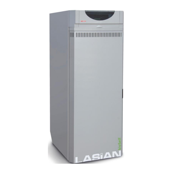
In case of damage, request a duplicate of it to the service center. Given the importance of the label, we recommend installing the boiler respecting the distances so that it is always visible. MODEL BIOSELF 18 kW BIOSELF 24 kW Nominal thermal output min./max. - Page 11 DIMENSIONS AND COMPONENTS MODELS BIOSELF 18 / 24 kW BIOSELF 18 / 24 kW COMPONENTS Control panel Ø 80 Flue duct Safety valve ¾ male discharge ¾ male return Air intake Electrical outlet Hopper lid Room thermostat connection COD. 79101EN.00...
-
Page 12: Fuel
6 or 8 mm. etc. This LASIAN boiler has an ash cleaning system that allows these fuels to be used in the devices, choosing the specific... -
Page 13: Installation
The use of fuel not according to the manufacturer's instructions can damage the boiler and compromise its performance, resulting in the invalidation of the warranty and in the end of the liability of the manufacturer on the product. 4. INSTALLATION 4.1 GENERAL NOTES Do not install the boiler in bedrooms, locations with bath or shower and in places where there is another heating unit devoid of an adequate airflow (chimney, stove, etc.), outside exposed to the atmospheric agents or in wet... -
Page 14: Minimum Safety Distance
4.4 MINIMUM SAFETY DISTANCE The following figures show the minimum safety distance that must always be guaranteed. INSTALLATION IN ANGLE (mm) Chimmey Passing pipe insulation Boiler Walls INSTALLATION TO WALL (mm) Safety distance of the flammable material minimum distance air from flammable posterior wall P = 400 minimum distance air from flammable side wall L = 400... -
Page 15: Floor Protection
DISTANCE FROM FALSE CEILINGS OR DISTANCE FROM THE FLUE DUCT OF FLAMMABLE CEILINGS (mm) FLAMMABLE WALLS INSTALLATION (mm) 4.5 FLOOR PROTECTION In case of heat sensitive or flammable floors is necessary to use a floor protection, eg: Steel sheet, marble or tiles. Whatever type of protection is chosen, it must protrude at least 300 mm from the front, and at least 150 mm from the sides of the boiler, support the weight of the boiler and have a thickness of at least 2 mm fig. -
Page 16: Duct Or Chimney
4.6 DUCT OR CHIMNEY Each appliance must have a vertical duct or chimney to expel outside the fumes produced by combustion. Flue duct must meet the following requirements: Do not connect to any other fireplace, boiler, boiler or any kind of extractor (fig. 1) It must be adequately separated from combustible or flammable materials by a cavity wall or an insulating material. -
Page 17: Flue Duct Outlet
4.7 FLUE DUCT OUTLET 4.7.1 GENERAL NOTES ATTENTION! The use of various fuels distinguishes this boiler from the others. The draw of the smoke is forced thanks to an extractor that keeps the combustion chamber in depression and all the discharge pipes under a slight pressure. -
Page 18: Hole In Flue Duct Pipe
4.7.3 HOLE IN FLUE DUCT PIPE Once the boiler location is established, it is necessary to make the hole for the flue duct pipe. This varies depending on the type of installation, diameter of the unloading pipe and type of wall or ceiling that it is going to pass through. -
Page 19: Use Of External Chimney
4.8. USE OF EXTERNAL CHIMNEY An external flue can be used provided it complies with the following requirements: • Use only insulated double-walled stainless steel pipes fixed to the building. • There must be an inspection opening at the base of the flue to permit periodic checks and maintenance. - Page 20 Surpass Fig. 1 Fig. 2 Minimum height of Pitch of the roof Horizontal width of reflux Height of reflux area Z outlet from roof [°] area from ridge axis A[m] Hmin =Z+0.50m 1.85 1.00 0.50 1.50 1.30 0.80 1.30 2.00 1.50 1.20 2.60...
-
Page 21: Fresh Air Intake
4.10 FRESH AIR INTAKE The boiler must have the necessary air to ensure a trouble-free and correct performance of the combustion, as well as a good environment. Make sure the room where the boiler is installed has adequate ventilation, and if not, install an air supply duct from the outside with a recommended minimum section of 100 cm². -
Page 22: Connections
5. CONNECTIONS 5.1 ELECTRICAL CONNECTION The system must be suitable for the electrical power of the boiler. The boiler is supplied with a power cable that needs to be connected to a 230V 50Hz outlet. The connection of the outlet to the back of the boiler is shown in the figure. -
Page 23: Use
Incorrect installation or poor maintenance (non-compliant to what it was stated in this manual) may cause damage to people, animals... In this case, Lasian will be exempt of any civil or criminal liability. If during the ignition phase, this does not occur and you notice a lot of smoke in the combustion chamber, turn off the boiler and replace the fuel as the humidity could be too high. -
Page 24: Loading The Pellets
6.3 LOADING THE PELLETS The load of fuel is made through the upper side of the boiler. Pour the pellet in the tank. Never remove the protection grille inside the tank. During the load, prevent the sack of pellet from contacting hot surfaces. Fill the tank only with the fuel that meets the aforementioned specifications. -
Page 25: Shutdown
Temp. Control. Maintenance: if the fumes temperature falls below the maintenance temperature for more than 3 minutes, the current regimen of operation is increased to the next regimen. Extinct of flame control: if the fume temperature decreases below the extinction of the flame temperature, flame extinction alarm is activated. -
Page 26: Control Panel Instructions
7. CONTROL PANEL INSTRUCTIONS 7.1 START-UP SCREEN When the boiler is on, after a few seconds from the ignition, the display shows the following information on the screen: Room temperature Current date current time Operation regimen from 1 to 6 when the boiler is on * Boiler state * During the operation phase, the screen shows the power of the boiler from 1 to 6. -
Page 27: Programs Menu
7.2 PROGRAMS MENU From the main screen you can access to the menu programs by pressing the SET button; using ▲ and ▼ the following screens will be displayed sequentially, from where you can leave at any time by pressing the button Temp. -
Page 28: Programmed Start-Up And Shutdown
It allows you to reschedule the current time. With the keys ▼ Hours and ▲ you can modify the time; press SET to confirm or the key to exit without saving the modifications. 11:08 7.5 PROGRAMMED START-UP AND SHUTDOWN After pressing Set to access the menu, press SET again to enter the submenu Ignition. This function allows you to switch on/off the boiler with scheduled times: thanks to the internal clock and buffer battery Ignition... - Page 29 As you can see, only the days from Monday to Friday are capitalized. Once days selected, press Timer 01 MTWTFss to confirm: now the text “MTWTFss” will start flashing again. To go to the next parameter, press the key ▲. The text “on00:00” on00:00 off00:00 will now flash.
- Page 30 The text “Timer01” stops flashing: We change the value with the keys ▲ and ▼ until the text “Timer02” appears. You will see that Timer02 mtwtfss when choosing a new program, all the days of the week appear deactivated, and the connection/disconnection time (on/off) are all in on00:00 off00:00 00:00.
- Page 31 To start, we press the key ▲ so that the text “Timer02” starts Timer02 MTWTFss flashing. When “Timer02” is flashing, it indicates that the program is in On17:00 off23:00 selection. To change to other programs, it is necessary to press SET. The text “Timer02”...
-
Page 32: Fuel
Timer03 mtwtfSS With the keys ▲ and ▼ we can set the time at 20:00 and press SET to confirm it. From now the text “off 20:00” will start flashing again. on08:00 off20:00 The schedule is finished, with only three timings the startup and shutdown time for all the week has been set. Having 16 timers available, allows covering different time slots for each day and different days of the week. -
Page 33: Alarm Descriptions
7.8 ALARM DESCRIPTIONS ALARM DESCRIPTION SOLUTION Lack of fuel in the tank Load fuel and try to switch on the boiler again Presence of fuel remains in the Clean the burner and try to switch on the boiler again burner FAILED IGNITION Empty the tank with a long neck vacuum cleaner and Lack of fuel in the burner... -
Page 34: Safety Temperature Limiter And Room Thermostat
Check the water pressure. See paragraph 7.7 Water pressure sensor opening LOW PRESSURE H If the problem persists, call a T.A.S. in your area Check the water pressure. See paragraph 7.7 Water pressure sensor opening HIGH PRESSURE H If the problem persists, call a T.A.S. in your area Reset the manual thermostat. -
Page 35: Warnings And Maintenance
8. WARNINGS AND MAINTENANCE All maintenance operations (cleaning, possible replacements, etc.) must be made with the fire off and when the boiler is cold. Before carrying out any cleaning or maintenance, preventively ensure that the boiler is unplugged from the mains intervening in the general switch placed behind the boiler or disconnecting the power cable that feeds it. -
Page 36: Combustion Chamber Cleaning
Fig. 1 Fig. 2 Fig. 3 To remove the ashes, check paragraph 8.2. 8.5 COMBUSTION CHAMBER CLEANING Periodically it is necessary to do the combustion chamber cleaning. With an ash vacuum, vacuum the ash accumulated. Take out the front element (see Fig.1) and the two side elements of the combustion chamber (see Fig.2) unscrewing the screw situated on the top of the frontal element, then disengage the three pieces. -
Page 37: Smoke Chamber Cleaning
Fig. 1 These actions can ONLY be done when the boiler is off and cold. 8.7 SMOKE CHAMBER CLEANING Usually once a year (preferably at the beginning of the season), the extraordinary cleaning of the smoke chamber must be performed to allow a correct operation of the boiler. The frequency of this operation depends on the type of fuel used and the frequency of use. - Page 38 COD. 79101EN.00 11/2013...
-
Page 39: Warranty Conditions
Do not handle the inside of the boiler. If you doubt of its correct performance, please read carefully the instruction manual included with each appliance or consult your local Technical Service. To maintain an optimal operation of the boiler or heating unit LASIAN, we recommend an annual review of the same by a member of our T.A.S. or an entity authorized by LASIAN Tecnología del Calor S.L., which for convenience we recommend you to perform it at the end of the heating season. - Page 40 COD. 79101EN.00 11/2013...
-
Page 41: Cod. 79101En.00
USER DATE WORKING HOURS INTERVENTION SIGNATURE SIGNATURE COD. 79101EN.00 11/2013... - Page 42 USER DATE WORKING HOURS INTERVENTION SIGNATURE SIGNATURE COD. 79101EN.00 11/2013...
- Page 43 USER DATE WORKING HOURS INTERVENTION SIGNATURE SIGNATURE COD. 79101EN.00 11/2013...
-
Page 44: Technical Service
The manufacturer assumes no responsibility for damages caused to persons or things from accidents that are not exclusively from the boiler itself as an individual unit and for manufacturing defects. NOTE: The manufacturer reserves the right to make product changes without notice, always maintaining the technical and essential service characteristics to fulfill the purpose for which the boiler is intended.
Need help?
Do you have a question about the BIOSELF and is the answer not in the manual?
Questions and answers