Advertisement
Quick Links
Advertisement

Related Manuals for DRAKE SP75

Summary of Contents for DRAKE SP75
-
Page 2: Table Of Contents
TABLE OF CONTENTS PAGE General Description ..... Specifications ... . III. - Page 3 Fig. 4 Tape Player Connection to SP75. Fig. 5 P. C. Board Pictorial, SP75 Fig. 6 Schematic, SP75 ....../ ...
-
Page 5: General Description
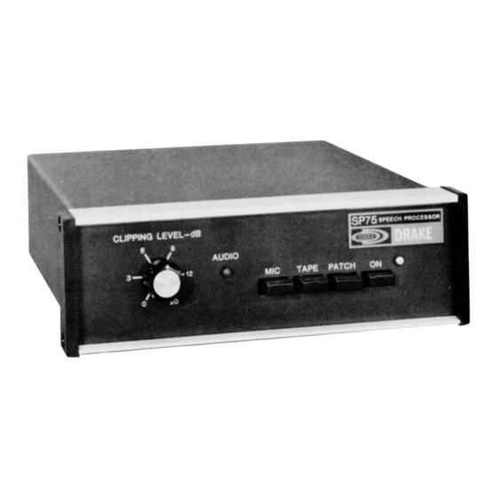
I. GENERAL DESCRIPTION The SP75 Speech Processor is designed to provide an increase in average power and readability of a single sideband voice signal during weak signal or high interference conditions. The SP75 is connected between the microphone and microphone input of the single sideband transmitter, thus requiring no modification of the existing transmitter or transceiver. -
Page 6: Installation
Weight: III. INSTALLATION Locate the SP75 at a convenient location. If the SP75 is placed on top of the TR7 transceiver, the microphone cable from the rear of the SP75 can be routed along the side and underneath the TR7. DO NOT block the power amplifier cooling slots on the right side of the TR7. - Page 7 Plug the SP75 output cable into the TR7 microphone input connector. Plug the phono plug on the SP75 supply cable into the 13.6 volt accessory output jack on the PS7 power supply. The microphone may then be connected to the SP75 input.
-
Page 10: Operation
IV OPERATION Before operating with the SP75 it may be necessary to set the SP75 microphone gain and output audio levels. Once these adjustments are made it should not be necessary to readjust them unless a microphone with a different output level is used. -
Page 11: Theory Of Operation
TAPE or PATCH mode and the level must be set by the control on the tape player or patch. Once the SP75 has been adjusted as per the above procedures it is ready for operation. One of the three possible inputs can be selected by depressing the appropriate interlocking pushbutton. -
Page 12: Alignment And Troubleshooting
VI. ALIGNMENT AND TROUBLESHOOTING The following procedures may be used to align the SP75 if there is good reason to believe alignment is required. There are only two adjustments in addition to the normal microphone gain and output level set-up. -
Page 13: Service Data
5) Approximately 25 mV at test point 12. VII. SERVICE DATA The SP75 will be checked and aligned at the factory for a nominal fee if there is no evidence of tampering. Transportation charges are extra. Any necessary repairs will be made on a time and materials basis. Please write or call the factory for authorization before returning your unit for alignment or service.
Need help?
Do you have a question about the SP75 and is the answer not in the manual?
Questions and answers