Advertisement
Quick Links
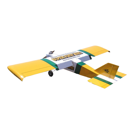
BUILDING INSTRUCTIONS FOR THE BTE
phone:
541-582-1708
orders:
800-557-4470
website:
www.btemodels.com
e-mail:
bruce@btemodels.com
Written by Bruce Tharpe
Wingspan: 132 inches
Wing Area: 3380 square inches
Length: 96 inches
Weight: 36 pounds (approximate)
Engine Range: 60cc - 80cc Gas
Manufactured by
B
T
RUCE
8622 E EVANS CREEK ROAD, ROGUE RIVER, OR 97537
E
HARPE
NGINEERING
June 2013
Advertisement

Related Manuals for BTE SUPER FLYIN' KING

Summary of Contents for BTE SUPER FLYIN' KING
- Page 1 BUILDING INSTRUCTIONS FOR THE BTE Written by Bruce Tharpe June 2013 Wingspan: 132 inches Wing Area: 3380 square inches Length: 96 inches Weight: 36 pounds (approximate) Engine Range: 60cc - 80cc Gas Manufactured by RUCE HARPE NGINEERING 8622 E EVANS CREEK ROAD, ROGUE RIVER, OR 97537...
- Page 2 " " " " TABLE OF CONTENTS !"# $! % & & !"# $! % & & !"* ! ! $% % $ !" !"# $! % ! .( ! !"# $! % ! $!2 % $# $ % 3 4 % 5 $ 4 !4 $!2 % $"...
- Page 3 Cut at the dotted lines to connect the drill holes, front and rear W-2 and one W-4 " & " !! # ! * + , " # !/ !! ! " " # !/ " " Left Outer Wing Panel, Inboard End - Plywood W-2 rib is set at the proper dihedral angle using the 5/32"...
- Page 4 !" % &' ( " % &* . (' . (% . (2 Center Wing Panel - Notice the screws holding the bottom main spar to the table. The front . (* . (' . (' screw needs to be removed before the shear web can be added.
- Page 5 PAGE 4 WING JOINER INSTALLATION > Prepare the wing joiners exactly as described in the Sig directions. Okay, maybe one exception: If you don't have numbered drill bits (like me), you can use a 7/64" drill for the 4-40 bolts (the mounting bolts, not the set screws) and a 9/64"...
- Page 6 PAGE 5 WING JOINER INSTALLATION, CONTINUED... Remove the outer panel and the webs. Drill at the marks (9/64’), put the webs back in the outer panel, then slide the outer panel into its final position against the center panel. Bolt the joiners to the webs with this hardware: Each Front Joiner - Three 6-32 x 1"...
- Page 7 PAGE 6 WING SUBASSEMBLIES > Time for a bit of tedium here. Once these time-consuming tasks are done, you will be ready to take on the final assembly of the wing panels with minimal delay. Let's roll... Sort the Balsa Sheets Go through the 3/32"...
- Page 8 PAGE 7 WING SUBASSEMBLIES, CONTINUED... Center Sheeting You'll need four 36" sheets to make two center sheets (one top, one bottom) for the wing center panel. If you look ahead, you will see that I got a little fancy with my Center Sheeting - Make 2 center and wing joint sheeting, adding curved edges to the 12"...
- Page 9 PAGE 8 FINISH OUTER WING PANELS > Bevel full thickness of bottom trailing edge spar Sand the back edge of the panel as shown in the diagram. Use a long sanding block and straightedge to be sure the trailing edge is straight along its entire length.
- Page 10 PAGE 9 FINISH OUTER WING PANELS, Continued... Unpin the TE, then pin or weight the panel down on the table, this time with the top spar against the table. Support the TE with a stick, then take a long careful look at the panel from all angles to be certain it is warp-free. This is your last chance to build a flat wing panel;...
- Page 11 PAGE 10 FINISH CENTER WING PANEL > Check for excess epoxy near the aluminum channels and sand it away so it won't interfere with sheeting. Sand the back edge of the panel on each side of the long ribs, just like in the figure in Section 5. Sand the bottom trailing edge spar, just like the previous step, in the two outermost rib bays between the W-1 ribs.
- Page 12 PAGE 1 1 FINISH CENTER WING PANEL, Continued... Flip upside down, pin the top TE sheeting flat to your table, and support the LE with wood. Cut and fit two more chunks of balsa laminate to fit between the W-1 ribs at the trailing edge spar.
- Page 13 " " & ' ( Drill for Control Horn Bolt " Drawing is not to scale - ' . - ' . " Aileron - with the the bottom sheeting, spars, and ribs glued in place. Trailing edge still needs to be beveled to match the slope of the ribs.
- Page 14 I glued in short Fin ready for final sanding. Note the hard points. Tail bracing is required on the Super Flyin' King. lengths of 1/2" dowel for my Sullivan Super Horns.
-
Page 15: Engine Installation
PAGE 14 FUSELAGE DECISIONS > No construction here, but this deserves its own section because I literally spent days thinking about these items before starting on the fuselage. I'm the type that likes to plan way ahead when it comes to the engine and radio installation. -
Page 16: Radio System
1-3/4" Du-Bro tailwheel. The Graph Tech #304 assembly is a high-quality alternative (available from BTE). If you choose something else, be sure it's rated for at least a 35 lb. model. Tailwheel and Rudder Cables - I used Du-Bro 4-40 pull-pull cables on both the rudder and the tailwheel. - Page 17 " # $ % & " Engine Spacer built from 1/2" plywood. Total thickness is one inch. Carb must be installed after engine is bolted to spacer. " # $ % & # $ % & ( ) * # ./ 0 .- 0 F-1 shows carb cutout and four mounting holes for spacer.
- Page 18 " # $ % & '( " " " " " " " # $ % & '+ & , " Fuselage Sides with Doublers shown here. 0 1 $ 2 " 4 5 6 " " " " '3 8 2 %1 .
- Page 19 " " " " " + , 3 / , " # " " " # " " # " & " Fuselage Front End shows the stick and rubber " " band squeezing tool. I used a straight channel of aluminum taped to each side in the cabin area to "...
- Page 20 " " Wing Saddle reinforced with 1/32" ply, indicated by arrow. Also note the balsa triangle stock at the front, sanded to con- form to the shape of the wing saddle. & The hardwood rails inside the cabin area below the windows were added to my model to support false floors which, of course, I've yet to finish..
- Page 21 ! " % & & ( ( ! Fuselage Rear - I know, the gussets and diagonals are missing in this photo. The prototype wasn't built in exactly the same order & as the instructions. This photo does show the final result of the fin front "pocket".
- Page 22 PHOTO 1 ! " # & PHOTO 2 & % - . ! 0 1 % * 3 & $ PHOTO 3 PHOTO 4 & ! "- # &...
- Page 23 PHOTO 1 " $%& PHOTO 2 ( ) * + + ! ! $& " PHOTO 3 . ' & $ ' % & 2 3 PHOTO 4...
- Page 24 PHOTO 5 " ) PHOTO 6 " 0 $%& PHOTO 7 " PHOTO 8 PHOTO 9...
- Page 25 " , " PHOTO 10 PHOTO 11 " PHOTO 12 " 5; , < < > " " @...
- Page 26 " " & " ( ) & PHOTO 1 " #$ % & & & PHOTO 2 & * #+ , PHOTO 3 Speaking of "Tail Braces" Here's a little safety feature that was built into the prototype. The eyelet isn't for towing banners, it's an attachment point for a rope to hold the model during starting.
-
Page 27: Control Throws
BALANCE " " " % &' " ) " " " "" " " " " " " " " ." CONTROL THROWS " " " " " " " RECOMMENDED CONTROL THROWS AILERONS: 1-5/8" UP, 1" DOWN ELEVATOR: 1" UP, 1" DOWN RUDDER: 1-1/2"... - Page 28 ! " # $% & % * $+ , 0 12 $ " & " <...
- Page 29 Sullivan Super Horn Set - This package contains all the heavy-duty control horns you will need; the same horns as used on the BTE prototype and shown throughout this book. Includes six Super Horns (for ailerons, flaps, and split BTE Price..$34.95 elevators), one Double Super Horn (for the rudder), and Sullivan 4-40 Gold-N-Clevises.
- Page 30 BALSA STICKS WING JOINER SHEAR WEBS " # $ % # $ $ & " ' ( & ) * - . / & # $ % # $ % # & " ' ( ! ) * - . + # # 1 # 2 0 .
Need help?
Do you have a question about the SUPER FLYIN' KING and is the answer not in the manual?
Questions and answers