Table of Contents
Advertisement
Advertisement
Table of Contents

Related Manuals for Asset ATLANTIS 60

Summary of Contents for Asset ATLANTIS 60
- Page 1 Rev. February 2011 - Code Man-02-ENG ATLANTIS prodotto conforme D.M.174/2004 ASSET S.r.l. Loc. Isola del Pero, 16 - 17041 - ALTARE (SV) - ITALY Tel: +39 019 58 48 30 Fax: +39 019 51 42 186 - e-mail: info@assetitalia.it - www.assetitalia.it...
- Page 2 prodotto conforme D.M.174/2004 Certificate Number TIFQ-1206TA03F3P7 HEAVY METAL ABSENCE 94/62/CE...
-
Page 3: Table Of Contents
Thecnical assistance service ......1-8 Copyright ........1-8 CHAPTER 2 TECHNOLOGICAL DESCRIPTION ........2-1 Available models ........2-1 2.1.1 atlantis 60/120 ........2-1 Technical data ........2-2 Emission of machine noise ....... 2-5 CHAPTER 3 SAFETY REQUIREMENTS ........3-1 General notes ........ - Page 4 CHAPTER 6 DISPENSER USE ........6-1 Control panel ........6-1 First start up ........6-2 Temperature setting ........6-4 Ice bank defrosting ........6-4 Ice bank emptying and ice bank water replacement ........6-5 Touch screen user interface ......6-6 Anomalies signalling leds ........ 6-7 Touch Models Dispay ........
- Page 5 ATLANTIS - Installation, Use and Maintenance - Man cod.-02 - Rev. 02/2011...
- Page 6 ATLANTIS - Installation, Use and Maintenance - Man cod.-02 - Rev. 02/2011...
- Page 7 5.1a Outer connections on upper part of Atlantis 120 ..5-2 5.1b Outer connections on back side of Atlantis 120 ..5-2 Outer connections on back side of Atlantis 60 ..5-2 Taps assembly ........5-3 Taps tightening ........5-3 Stainless steel tap for sparkling water ....
- Page 8 Dispenser upper part ........6-3 Safety valve ring ........6-3 Cold water dispensing tap ........6-4 6.10 Thermostat for water temperature adjustment ..6-4 6.11 Control Panel (Touch Models) ....... 6-7 CHAPTER 8 MAINTENANCE ........8-1 Monouse bottle replacement ....... 8-2 Rechargeable bottle replacement ......
- Page 9 Dear Customer, Asset Srl would like to thank you and congratulate for your choice. Water is a vital and essential element. Water represents 70% of the human body and, every day, we ought to drink at least 2 litres of it to be in health and to refresh ourselves.
- Page 10 ATLANTIS - Installation, Use and Maintenance - Man cod.-02 - Rev. 02/2011...
-
Page 11: Chapter 1 Introduction
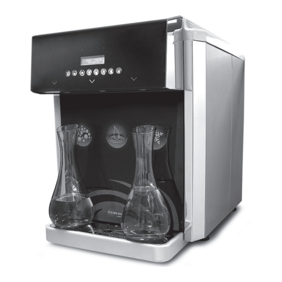
This device, that in the course of the manual will be ge- fig.1.1 ATLANTIS 60/120 nerically called “machine” or “dispenser”, is manufactured by the company ASSET srl, whose details are indicated hereinafter in this publication. This publication is intended for subjects, generically defined as ‘users’, who are intended to use the machine. -
Page 12: Aim Ofo The Manual
1.2 Aim of the manual The aim of this manual is to give the indications to use the machine safely and to carry out the ordinary main- tenance procedures. Any calibrations, adjustments and extraordinary mainte- nance operations are not included in this booklet, since they are carried out exclusively by the service techni- cian, that must operate on the machine in respect of the technical and project characteristics for which is... -
Page 13: Manual Updating
All property rights of the contents included in this publi- cation are reserved to Asset s.r.l., therefore it cannot be reproduced totally or partly unless written authorization by the manufacturer. -
Page 14: Manufacturer
1.6 Manufacturer The machine identification data are included in the label positioned on the rear of the machine. fig.1.3 The label includes the following data in this order: - model; - serial number; - power supply voltage (V), frequency (Hz), absorbency only of the refrigerant part (A) and the pertaining Climatic Class;... -
Page 15: Manufacturer's Responsibility And Warranty
Country where the machine will operate. 1.7.1 Warranty terms The machine is guaranteed by ASSET srl for a 24 (twenty four) month period from the invoice date. This guarantee covers manufacturing and assembling defects. -
Page 16: Copyright
it is understood that the travel, board and lodgings costs are at user’s charge. The acknowledgment of a free supply of the parts under warrantee is always subject to inspection by the Manu- facturer (or authorized person). The extension of guarantee following a technical inter- vention or repair of the machine is excluded;... - Page 17 DICHIARAZIONE DI CONFORMITA’ CE EC DECLARATION OF CONFORMITY 2004/118/EC, EC 2006/95/EC. 2004/118/EC, 2006/95/EC. ASSET S.r.l. ASSET S.r.l. Loc. Isola del Pero, 16 - 17041 Altare (SV) - Italy Loc. Isola del Pero, 16 - 17041 Altare (SV) - Italy dichiariamo sotto la nostra responsabilità che il...
- Page 18 Intentionally blank page 1-10 ATLANTIS - Installation, Use and Maintenance - Man cod.-02 - Rev. 02/2011...
-
Page 19: Technological Description
The ATLANTIS 60/120/180 range is a quiet, easy to install and use dispenser with low power consumption that stands out for its stylish line and compactness. -
Page 20: Technical Data
3 cold water dispensing tap; 4 drip tray equipped with supporting grid. fig.2.2 2.2 Technical data The following data are related to the dispenser with serial configuration. ATLANTIS 60 TABLE TOP 220/230V 50/60Hz POWER SUPPLY VOLTAGE monophase 670W - 2,9A... - Page 21 CARBONATION SYSTEM Saturator MINIMUM INLET WATER TEMPERATURE 5 °C / 41°F MAXIMUM INLET WATER TEMPERATURE 25 °C / 77°F DISPENSED WATER TEMPERATURE Adjustable 2÷8 °C 16l/h ∆t = 10 °C / 50 °F COLD AND SPARKLING WATER OUTPUT (Room Temperature 25°C / 77°F - Humidity 75%) WATER INLET FITTING Quick Fitting - Ø...
- Page 22 ROOM WORK TEMPERATURE 10-32 °C / 50-89,6°F COMPRESSOR POWER 350W QUANTITY OF REFRIGERANT GAS R134a 125g CONDENSATION OF VENTILATED AIR WATER PUMP TYPE Rotary CARBONATION SYSTEM Saturator MINIMUM INLET WATER TEMPERATURE 5 °C / 41°F MAXIMUM INLET WATER TEMPERATURE 25 °C / 77 °F DISPENSED WATER TEMPERATURE Adjustable 2÷8 °C 120l/h ∆t = 10 °C / 50 °F...
- Page 23 ATLANTIS 180 Touch TT TABLE TOP 220/230V 50/60Hz POWER SUPPLY VOLTAGE monophase 680W - 3,1A MAX POWER CONSUMPTION Climatic Class SN ROOM WORK TEMPERATURE 10-32 °C / 50-89,6°F COMPRESSOR POWER 520W - 1/3 Hp QUANTITY OF REFRIGERANT GAS R134a 190g CONDENSATION OF VENTILATED AIR WATER PUMP TYPE Rotary...
- Page 24 YES - MAX 2 waters SIMULTANEOSLY DISPENSED WATERS simultaneously ANTY-LEAKAGE SECURITY VALVES Included SOUND PRESSURE LEVEL 50 dB(A) SOUND POWER LEVEL 62 dB(A) Min 2 °C/35,6 °F - Max 40 STORAGE TEMPERATURE min/max °C/104 °F DRAIN PIPE FOR TANK TOO FULL Directly in the drip tray ATLANTIS 180 US - Under Sink UNDER SINK...
- Page 25 NET WEIGHT (ACCESSORIES EXCLUDED) 44 Kg GROSS WEIGHT (ACCESSORIES EXCLUDED) 48 kg DISPENSER DIMENSIONS LxWxH 455x300x700mm INCLUDING DRIP TRAY PACKAGE DIMENSIONS LxWxH 490x330x730mm SOLENOID VALVES DISPLAY AUTO DOSING SYSTEM OZONE SANIFICATION SIMULTANEOSLY DISPENSED WATERS ANTY-LEAKAGE SECURITY VALVES SOUND PRESSURE LEVEL 50 dB(A) SOUND POWER LEVEL 62 dB(A)
-
Page 26: Emission Of Machine Noise
2.3 Emission of machine noise The noise level with continuous operation is less than 70 dB(A). These data are available in the Technical File in the Manufacturer’s archive. ATLANTIS - Installation, Use and Maintenance - Man cod.-02 - Rev. 02/2011... -
Page 27: Safety Requirements
Safety requirements 3.1 General notes The dispenser was designed and manufactured in compli- ance with the requirements of the Machinery Directive 2006/42/EC, taking into account its ordinary use and the WARNING reasonably intended use. Before carrying out any operation The dispenser was manufactured for the application on the machine it is neces- sary to read the whole manual mentioned in the declaration of conformity enclosed to... -
Page 28: Safety Warnings
• The repair of the product must be carried out only by a skilled technician or in a Service Centre authorized by Asset srl, for your security and in compliance with the standards. • Install the water dispenser in a proper way to guar- antee a right ventilation for the machine cooling or a distance –... -
Page 29: Operator's Qualification
• Interventions not specified in this manual must be carried out only by skilled staff or in one of Asset’s authorized Service Centres. • This device is not intended to be used outdoors in the rain and/or snow 3.3.1 Operator’s qualification... - Page 30 Intentionally blank page ATLANTIS - Installation, Use and Maintenance- cod. Man-02 - Rev. 02/2011...
-
Page 31: Chapter 4 Unpacking
Unpacking 4.1 Visual check At the arrival the packaging shall be in perfect condi- tions: - without signs of collision or breaks; - without signs that lead to suppose that it was exposed to heat sources, frost, water , etc.; - without signs of tampering. -
Page 32: Unpacking
- 3/8” fitting for connection to the water mains - CO connection hose diameter 4 mm - n° 3 taps (Atlantis 60 e 120 Model ONLY) - this manual ATLANTIS - Installtion, Use and Maintenance - Man cod.-02 - Rev. 02/2011... -
Page 33: Chapter 5 Installation
Installation Environmental characteristics The operating environment must have the following characteristics: CAUTION - Temperature: + 5 ÷ + 40 °C (41 ÷ 104 °F) If environmental conditions differ- ent than those required are noticed - Maximum relative humidity: 80% during installation, or if they change over time, immediately contact the The dispenser must not be used in open areas and/or Manufacturer beforeusing the dis-... -
Page 34: Connections
However, the water dispenser positioning must allow IMPORTANT sufficient ventilation, in particular, its back and upper In accordance with UNI EN 10380 sides must have a minimum free space for ventilation standard lighting for a generic working area must be of 300 lux of at least of 15 cm. -
Page 35: Taps Assembly
5.4.2 Taps assembly The device is supplied with disassembled taps, therefore it is necessary to reposition them. Proceed as follows (see fig. 5.3): - insert the conical part of the tap in the tap holding cavity already assembled on the dispenser; - Turn the chrome ring nut counterclockwise screwing it on the tap until the two parts... -
Page 36: Water Filter Insertion (Optional)
5.4.3 Water filter insertion (optional) WARNING Use specific filters that dose Proceed as follows: anti-limescale products to pre- vent the formation of limescale in the hot parts of the device. - cut the water supply tube in the insertion point of the prefilter - insert the supply tube, interception valve side, on the inlet fitting of the prefilter... -
Page 37: Connection To The Water Mains
5.4.5 Connection to the water mains Any temporary connections are forbidden for a good func- tioning of the dispenser. The following operations must be carried out by a skilled staff. During the installation, new water supply pipes for con- nection to the water mains must replace the old ones that must not be used again. -
Page 38: Power Supply Connection
4. connect the free end of the tube to the water inlet fitting positioned on the back side of the dispenser 5. open the interception valve to check that there are no leakages from the fittings previously assembled. 6. It is suggested to carry out the dispenser sanitization by using the appropriate kit (optional and not supplied with the dispenser) Water supply connections with a length longer than 4-5... -
Page 39: Connection Of The Co
Before inserting the power connection plug of the dispenser in the socket, make sure that the main switch is positioned on O (see photo) and then open the water interception valve and the CO2 bottle, fill the ice bank tank up to the level indicated (see fig. - Page 40 Open the (rechargeable) gas bottle by turning the upper handgrip counterclockwise (fig. 5.14). fig.5.14 Turn clockwise the black knob of the pressure reducer (screwing deeply towards the + sign) and check that there are no leakages on the connection points by using soapsuds water (fig.
-
Page 41: Dispenser Use
Dispenser use 6.1 Control panel Atlantis 60 and 120 models are professional water dis- IMPORTANT pensers with three hand tap dispensing points equipped The picture shows the position of with manually-adjustable flow regulator. the controls on a standard machine. Dispensing taps are identified by a symbol impressed on... -
Page 42: First Start Up
6.2 First start up (all models) After the carrying out all the operations described in chapter 5, proceed as follows: 1 lift the upper plastic cover of the device pulling it up; fig. 6.3 2 fill the ice bank tank (point 5) with clean water using a bucket or a carafe paying great attention to prevent wetting the electrical parts (thermostat and general... - Page 43 6 Pull the ring of the safety valve of the carbonator purging gas for at least 2/3 seconds (see at side); fig. 6.8 fig. 6.7 WARNING 7 Open the water interception tap; if the device is operated without water in the ice bank it will cause serious damage to the device.
-
Page 44: Temperature Setting
18 In case a similar anomaly occurs, follow the procedure described in paragraph “Ice bank defrosting”. 6.3 Temperature setting Atlantis 60, 120 and 180 are professional water dis- pensers equipped with ice bank refrigerating system controlled by a thermostat (see fig. 6.10). -
Page 45: Ice Bank Defrosting
6.4 Ice bank defrosting Lift the upper cover of the device (Atlantis 120 model), turn the knob of the thermostat on 0 and leave the switch on 1 (on). Close the cover and frequently dispense cold water from the right tap. The device must be power supplied at least for 12 - 24 hours. -
Page 46: Touch Screen User Interface
6.6 Touch screen user interface Atlantis 60, 120 and 180 Touch TT (Table Top) models are professional water dispensers with three dispensing points equipped with touch screen keypad and electronic display. The touch screen keypad technology is by now applied on... -
Page 47: Anomalies Signalling Leds
The symbols on the control keypad refer to the following functions: IMPORTANT The pictures shows the position of the controls on a standard machine. 1 - Cold sparkling water dispensing (Bottle - Fisrt Dosing) 2 - Cold sparkling water dispensing (Glass - Second Dosing) 3 - Save Dosing 4 - Room temperature water dispensing (Bottle - Fisrt Dosing) 5 - Room temperature water dispensing (Glass - Second Dosing) -
Page 48: Water Temperature Adjustment
6.9 Water Temperature Adjustment 1. The User Menu is accessed by pressing the front Menu Access Key for at least 3 seconds - or until the beep is heard; (same key must be used to scroll between the Menu sections). 2. -
Page 49: Automatic Water Dispesing Dosage
When the Energy Saving function is set to “0” (that means that the Energy Saving function is disabled) all the keys backlight are illuminated. When the Energy Saving function is set to “1” (that means that the Energy Saving function is enabled) all the keys backlight intermittent flash. -
Page 50: Enable Tone
To enable it, proceed as follows: 1. The User Menu is accessed by pressing the front Menu Access Key for at least 3 seconds - or until the ATTENTION To stop unintentional dispen- beep is heard; sing just press any key !!! 2. -
Page 51: Keyboard Lock
6.13 Keybord Lock The Keyboard Lock function allows to momentarily stop the dispensing function preventing unintentional dispensing and allowing to clean the keyboard without necessarily disconnecting power supply to the dispenser. To enable the keyboard lock press the key for at least 3-4 seconds; when the key illuminates with red light followed by a beep the function is active, [KEYBOARD LOCK] will appear on the display. -
Page 52: Dedicated Litre Counter
6.18 Dedicated Litre Counter ATTENTION: Dedicated Litre Counter function ONLY works if you have first enabled the Automatic Dispensing Water Dosage [DOSING] Function. Display will then show the total amount (expressed in litres) of the dispensed water, divided by typologies. •... - Page 53 Intentionally blank page 6-13 ATLANTIS - Installation, Use and Maintenance - Man cod.-02 - Rev. 02/2011...
- Page 54 Intentionally blank page 6-14 ATLANTIS - Installation, Use and Maintenance - Man cod.-02 - Rev. 02/2011...
-
Page 55: Chapter 7 Trouble Shooting
Trouble shooting 7.1 Solutions to problems The following table shows some operating problems of the dispenser that can be solved directly by the user without involving the service centers. PROBLEM CAUSE SOLUTION Closed water tap Open the tap Connection pipe to the Choose a path for the tap pressed;... - Page 56 The dispenser doesn’t dispense sparkling Replace or verify to have Lack of CO water when the opened the CO bottle sparkling water dispensing lever is pulled. The dispenser Disconnect the power supply dispenses only gas plug for about 30 sec. Then, when the sparkling Blocked pump connect it again.
- Page 57 Intentionally blank page ATLANTIS - Installation, Use and Maintenance - Man cod.-02 - Rev. 02/2011...
- Page 58 Intentionally blank page ATLANTIS - Installation, Use and Maintenance - Man cod.-02 - Rev. 02/2011...
-
Page 59: Chapter 8 Maintenance
Maintenance The buyer and/or user can only carry out the interventions specified in this manual. The manufacturer declines any responsibility for any WARNING intervention made by the buyer and/or user if not indicated All the maintenance operations in this manual. Interventions not specified in the manual must be carried out when the machine is switched off and and made by the buyer and/or the end-user during the... -
Page 60: Replacement Of The Monouse Or Rechargeable Co Bottle
Replacement of the monouse or rechargeable CO bottle When gas is over, the device starts dispensing less carbonated water and with a very reduced flow, so it is necessary to replace the CO bottle. CAUTION It is possible to use monouse or rechargeable bottles; Do not expose hands or any other the monouse can be utilized once;... -
Page 61: Filter Replacement
Screw again the hexagonal ring nut of the reducer on the new bottle and lock strongly with the adjustable spanner; open the upper hand-wheel of the bottle. Position the bottle in its place and block it with the proper chain or belt. 8.3a Filter replacement (No Touch Model) ATTENTION: This operation must be carried out by skilled... - Page 62 8.3b Filter replacement (Touch Model) ATTENTION: This operation must be carried out by skilled technical staff or by technical service center or by the authorized reseller only. ATLANTIS Touch Model is controlled by a microprocessor which, through special sensors, signals any malfunction and turns off the dispenser when dangerous conditions arise, such as leaks.
-
Page 63: Replacement Of The Uv Lamp (Outer Accessory)
cartridge of one-half turn and remove it by pulling down (fig. 8.6); insert again the new cartridge, pushing it up and screw it again of one-haft turn; open the interception tap of water and check the seal, press the temperature water dispensing key and dispense at least 10 litres of water;... -
Page 64: Water Dispenser Sanitization
use a new piece of blotting-paper slightly dampened with not aggressive detergent and disinfectant products diluted in water. Do not touch the dispensing points with dirty hands. Do not use solvents or alcohol-based products. The ventilation slits of the dispenser, on the right side, must be cleaned by using a dry brush. -
Page 65: Tap Sanitization
sanitization kit (optional - not included) using the dosing cap and then fill the water container to the rim (use preferably warm water). 5. Insert the container in place of the filter, pushing it up and screwing it half-turn making sure that it is correctly hooked in its seat. -
Page 66: Technical Assistance
8.7 Technical assistance In order to optimize the Support and Assistance service, ASSET makes use of a network of Resellers and Authorized Distributors that supports Clients for any possible request of Service. Therefore the Final User must only contact the Reseller where he purchased the machine for any request of Assistance or Technical Support. -
Page 67: Chapter 9 Dismantling
Dismantling 9.1 Dispenser dismantling The dispenser must be dismantled after disassembling the different parts that make it up. Request the Retailer for specific information regarding the dismantling operations. CAUTION Instructions related to this chapter are to be intended Once disassembled the different parts, subdivide the dif- just as an indication. - Page 68 Intentionally blank page ATLANTIS - Installation, Use and Maintenance - MAN cod.-02 - Rev. 02/2011...
-
Page 69: Chapter 10 Spare Parts
Spare parts 10.1 Identification and ordering modes Diagrams and drawings to identify the different parts are available in the technical file of the machine in the Manufacturer’s archives, therefore any request of spare parts must be sent to Manufacturer. For trading parts, if the Manufacturer considers it useful, it is possible to supply technical manuals or the original documentation of the supplier. - Page 70 Intentionally blank page 10-2 ATLANTIS - Installation, Use and Maintenance - Man cod.-02 - Rev. 02/2011...
- Page 71 Start up This device was started up on: by the qualified Company: Name of the Qualified Installer: Signature: Location address: Device owner: Maintenance certificate Hereby we confirm that the device was checked after the maintenance and repair service and is perfectly operating. Service carried out on: Date: Qualified Company:...
- Page 72 Loc. Isola del Pero, 16 - 17041 - ALTARE (SV) - ITALY - Tel: +39 019 58 48 30 Fax: +39 019 51 42 186 - e-mail: info@assetitalia.it - www.assetitalia.it ASSET declines all liability for any damage to people or property caused by incorrect use of this product. Subject to change without prior notice.
Need help?
Do you have a question about the ATLANTIS 60 and is the answer not in the manual?
Questions and answers