Table of Contents
Advertisement
Quick Links
READ AND SAVE THESE INSTRUCTIONS
TRUE TOUCHSCREEN CONTROLLED ELECTRODE STEAM HUMIDIFIER
Air Specialties Express, 448 S. Main St., P. O. Box 930040, Verona, WI 53593-0040
Door Lock
Blue
Fill LED
Red
Drain LED
Orange High
Water LED
Door
Interlock
Switch
AND MAINTENANCE MANUAL
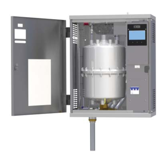
ASX "H" SERIES HUMIDIFIER
Cylinder
Drain Valve
Drain Pipe
Photo A
(Model HTGH Shown)
INSTALLATION, OPERATION
Phone: (877)945-9175
Distributor
Block
1
DESIGN SERIES "H"
Fax: (608)845-6504
www.airspecialties.com
On-Off-Drain
Switch
True
Touchscreen
Contactor
Circuit
Board
(Behind Door)
Voltage
Transformer
Current
Transformers
Circuit
Breaker
(Optional)
Ground Lug
FORM ASX-16834-I
ISSUED: 08-16
Advertisement
Table of Contents

Summary of Contents for Express SERIES “H”
- Page 1 READ AND SAVE THESE INSTRUCTIONS TRUE TOUCHSCREEN CONTROLLED ELECTRODE STEAM HUMIDIFIER DESIGN SERIES “H” INSTALLATION, OPERATION AND MAINTENANCE MANUAL Air Specialties Express, 448 S. Main St., P. O. Box 930040, Verona, WI 53593-0040 Phone: (877)945-9175 Fax: (608)845-6504 www.airspecialties.com ASX “H” SERIES HUMIDIFIER...
-
Page 2: Table Of Contents
TABLE OF CONTENTS Introduction - Cautions ....................... 3 Models ..........................4 Installation ........................5-9 Electrical Data Sheet and Definition ................10-12 Humidifier Component Listing - Combo Unit HT/SAH, HT/SDH & HT/SGH ....13 Controls ........................14-19 Operation .......................... 20 True Touchscreen - Displays and Internal Control .............21-27 Humidifier Mandatory Pre-startup Checklist .............. -
Page 3: Introduction - Cautions
INTRODUCTION CAUTIONS CAUTION! DO NOT INSTALL, USE OR OPERATE THIS EQUIPMENT UNTIL THIS MANUAL HAS BEEN READ AND UNDERSTOOD. READ AND SAVE THESE INSTRUCTIONS FOR FUTURE USE. CAUTION — Perform all basic safety steps before starting unit. 1. Proper mounting of unit cabinet to wall as described in following pages. 2. - Page 4 HSHH HTGH / HSAH / HSDH HRAB...
- Page 5 TYPICAL INSTALLATION Figure A High Limit Steam Humidistat Hose Steam Distributor Pipe Condensate Wall Humidistat Return Line Water Shutoff Valve (By Others) Air Flow Switch Cold Water Line Air Gap (Comes into the Fused Disconnect Drain Fitting bottom of the or Circuit Breaker humidifier) (By Others)
-
Page 6: Models
Table 1 - MAXIMUM OPERATING WEIGHT INSTALLATION Model Pounds UNPACKING AND INSPECTION H_AH 1. Inside the cabinet is an envelope containing the H_DH following items: H_GH A. Keys to the humidifier cabinet H_HH B. Steam hose clamps C. Condensate return line clamps Fasten the mounting bracket to wood studs or solid wood D. - Page 7 AFFECT ON CAPACITY DETERMINED BY STEAM HOSE Photo C LENGTH (Table 3-A) Distance Loss 10 Ft. 1.0 lb./hr. 20 Ft. 2.0 lb./hr. 25 Ft. 2.5 lb./hr. 40 Ft. 4.0 lb./hr. Figure B Outer diameter of drain pipe is 1-1/4”. Air gap fitting must be added. STEAM DISTRIBUTOR PIPE LOCATION It is critical to provide proper routing of flexible hose and hard tubing to maximize efficiency and...
- Page 8 If multiple pipes are used they should be staggered as shown in Steam line HOSE LOCATION Figure G. When hose is difficult to support must pitch FOR RUNS FROM within this length, straight down toward 12 FEET TO 40 FEET copper tube should be used drain tee —...
- Page 9 CONNECT THE STEAM HOSE It is very important that both the steam hose and condensate return line, whether flexible or hard tubing, be installed so COPPER OR BRASS TUBE IS THE ONLY ACCEPTABLE there are no sags, low points, dips, or horizontal runs. The SUBSTITUTE FOR CARNES STEAM HOSE OR CONDENSATE steam is at a very low pressure and it cannot overcome any HOSE.
-
Page 10: Electrical Data Sheet And Definition
ELECTRICAL CONNECTIONS WARNING: BEFORE MAKING ANY ELECTRICAL CONNECTIONS SWITCH POWER OFF AT SERVICE PANEL, FUSED DISCONNECT CIRCUIT BREAKER AND LOCK THE DISCONNECTING MEANS TO PREVENT POWER FROM BEING SWITCHED ON ACCIDENTALLY. POWER MUST BE OFF BEFORE MAKING ANY ELECTRICAL CONNECTIONS. Check unit electrical characteristics on the label on the outside of the cabinet. - Page 11 ELECTRICAL DATA AND UNIT DETAIL SHEET - Table 4 Optional Line Disc. Circuit Steam Cyl Wire Model Lb/Hr Voltage Phase Size Breaker* Cylinder Current H_AHAU 1.725 14.4 1-20 Amp AX220 14.4 H_AHBU 1.725 1-15 Amp AX380 H_AHDU 1.725 1-20 Amp AX380 H_AHFU 1.725...
- Page 12 ELECTRICAL DATA AND UNIT DETAIL SHEET - Table 4 (continued) Optional Line Disc. Circuit Steam Cyl Wire Model Lb/Hr Voltage Phase Size Breaker* Cylinder Current H_GHCU 17.2 47.8 2-35 Amp 23.9 H_GHEU 17.2 43.2 1-60 Amp 21.6 H_GHTU 17.2 26.2 1-40 Amp 26.2 H_GHWU...
-
Page 13: Humidifier Component Listing - Combo Unit Ht/Sah, Ht/Sdh & Ht/Sgh
HUMIDIFIER COMPONENT LISTING - Figure K On-Off-Drain Switch High Water Sensor (behind cylinder) 17. Cylinder Fitting Circuit Board 10. Fill Cup 18. Drain Valve Door Interlock Switch 11. Fill Valve (not shown) 19. Lock Voltage Transformer 12. Steam Hose 20. Water Inlet Hose Current Transformer 13. - Page 14 CONTROL CONNECTIONS - Figure L NOTES: 1. Observe proper polarity when using voltage or current measuring devices. 2. If air flow and high limit switches are not used, a jumper must be installed. Supplied By Carnes Supplied By Others WARNING: BEFORE MAKING ANY ELECTRICAL CONNECTIONS SWITCH POWER OFF AT SERVICE PANEL, FUSED DISCONNECT OR CIRCUIT BREAKER AND LOCK THE DISCONNECTING MEANS TO PREVENT POWER FROM BEING SWITCHED ON ACCIDENTALLY.
-
Page 15: Controls
CONTROLS CONTROL OPTIONS - Figure M CONTROL HUMIDISTAT AIR FLOW DETECTION CONDENSATION PROTECTION WALL HUMIDISTAT PROPORTIONAL CONTROL CARNES MODEL HXHCG WALL HUMIDISTAT PROPORTIONAL CONTROL DUCT ON-OFF PRESSURE CARNES MODEL HXHAM HIGH LIMIT DIFFERENTIAL HUMIDISTAT SWITCH CARNES MODEL HXHAD CARNES MODEL HXAAE WALL HUMIDISTAT ON-OFF CONTROL CARNES MODEL HXHAA... - Page 16 OPTIONAL ACCESSORY CONTROLS WALL HUMIDISTAT, PROPORTIONAL CONTROL The Model HXHAM is a wall-mounted, microprocessor-controlled Model HXHAM humidistat solution for humidity control. The HXHAM employs a backlit LCD module, which displays both the ambient temperature and humidity of the surrounding air. The embedded software allows user navigation between temperature/ humidity viewing mode, setpoint adjustment mode, and outdoor temperature/humidity viewing mode.
- Page 17 DUCT HUMIDISTAT, ON-OFF CONTROL PUSH SCREWDRIVER Model HXHAB IN AND HOLD MOUNTING HOLES - 2 PUSH IN PUSH TO COM. RELEASE - 3 RELEASE PUSH IN TERMINAL - 3 SETPOINT ADJUSTMENT This duct mounted humidistat is installed in the return air duct to sense the humidity level in the area being served.
-
Page 18: High Limit Humidistat
AIR FLOW SWITCH, PRESSURE DIFFERENTIAL TYPE When there is an increase of air pressure to above setpoint, the Model HXAAE switch is switched from normally closed (N.C.), common ground contact to normally open (N.O.) contact. On a decrease of air pressure to below setpoint, normally closed, common ground contact of the switch is switched to normally closed contact. - Page 19 CONDENSATION PROTECTION A third device may be desirable to provide condensation protection in the duct system. A high limit humidistat may be installed ten feet downstream from the steam distributor pipe. This humidistat is normally set to 90-95% RH and opens the circuit if the humidity level in the duct exceeds the setpoint.
-
Page 20: Operation
The circuit board also closes a power contactor allowing EXTERNAL MONITORING current to flow to vertical electrodes sealed inside the Pins 1 and 2 of connector J10, shown in Photo H, are provided for cylinder. Current flows between the electrodes using indicating operation of the humidifier at a remote location. -
Page 21: True Touchscreen - Displays And Internal Control
DISPLAYS AND INTERNAL CONTROLS FRONT PANEL DISPLAYS & CONTROLS The display on the front panel of the humidifier cabinet con- tains the “On-Off-Drain” switch, the LCD True Touchscreen display and the “Fill”, “Drain”, and “High Water” LED. “SERVICE REQUIRED” PAGE The “Service Required”... - Page 22 “DRAIN” LED The DRAIN LED is a red light illuminated when the Drain Valve is activated. An activated Drain Valve allows water to drain from the humidifier. An analogous indicator, and a description of its operation, is offered in the “Menu” screen under “Component Activity”.
- Page 23 3. Air Flow - Explains the status of the Air Flow switch. The Air Flow switch must sense proper air flow in order for the humidifier to activate. Insufficient air flow or an improperly installed air flow switch will cause the indicator to change to a red “X”...
- Page 24 The Controlled Setpoint is the Setpoint when a humidifier (Control or High Limit), reduces the target output of the humidifier due to changing room requirements. The Reduced Setpoint is active when the unit requires a reduction in output due to a high water situation. The Setpoints have the following priorities: The Reduced Setpoint has the highest priority and always overrides the Controlled Setpoint and the Max Setpoint when...
- Page 25 Cylinder Life Counter The help pages consist of buttons labeled with subjects. When a button is pressed, information will be given about the This page consists of a counter where the user can monitor subject in question. A basic help page consists of text and/or the life, in hours, of the cylinder.
- Page 26 Setpoint Timeout Boil Down Timer This page is where the Setpoint Timeout value is set. The This page is where the Boil Down Timer is set. The Boil maximum amount of time allowed for the unit to reach Down Timer is variable between 0 and 255 seconds, with Setpoint during a fill sequence is designated by the Setpoint a default value of 25 seconds.
- Page 27 CarnesLink Communication Protocol Setup Corrective Drain Length This page is where you can select and setup the This page is where the Corrective Drain Length is communication protocol you will be using with your Building set. This value represents how much water should be Management System (BMS) for full external monitoring drained from the cylinder when the humidifier senses a capabilities.
-
Page 28: Humidifier Mandatory Pre-Startup Checklist
HUMIDIFIER MANDATORY PRE-STARTUP CHECKLIST Unit Serial #: _____________________ No. of Humidifi ers: ______________________________________________ Model #: _________________________________ Voltage: _______ V/ ___ Ph. Steam Output: _______ lb./hr. Customer/Job: ___________________________ Address: ______________________________________________ WATER QUALITY: Well Water ______ City Water ______ Softened Water ______ Water Conductivity (if known): mhmos: ______ Hardness: ______ gr. -
Page 29: Humidifier Startup Checklist
HUMIDIFIER STARTUP CHECKLIST Unit Serial #: _____________________ No. of Humidifi ers: ______________________________________________ Model #: _________________________________ Voltage: _______ V/ ___ Ph. Steam Output: _______ lb./hr. Customer/Job: ___________________________ Address: ______________________________________________ PRELIMINARY: • Pre-startup Checklist completed If no, perform Pre-startup Checklist before starting humidifier. STARTUP PROCEEDURE: The prerequisites for the humidifier filling and contactor pulling in to make steam are as follows: ... -
Page 30: Humidifier Startup And Operations
HUMIDIFIER STARTUP & OPERATION Unit Serial #: _____________________ No. of Humidifi ers: ______________________________________________ Model #: _________________________________ Voltage: _______ V/ ___ Ph. Steam Output: _______ lb./hr. Customer/Job: ___________________________ Address: ______________________________________________ PRELIMINARY: • Pre-startup Checklist completed If no, perform Pre-startup Checklist before going to the starting procedure. ... -
Page 31: Fan Distribution Units
Fan distribution units must be mounted securely on a level and FAN DISTRIBUTION UNITS plumb surface at least three feet below the ceiling for a Model HXBHB and at least four feet below the ceiling for a Model Fan distribution units are available for use in areas which do not HXBHC to prevent steam condensing on the ceiling surface. - Page 32 A Remote Fan Distribution Unit comes with two separate male plugs to connect 12-conductor wire from the humidifier to the fan distribution unit at a remote location. One of the male connectors goes to the humidifier’s female connector, the other goes to the remote unit.
-
Page 33: Distribution Pipes
STEAM DISTRIBUTOR PIPES Lengths 012-036 5” (127) 9-1/2” (241) 3/8” Lengths 048-120 4” (102) 4” (102) 3/8” Distributor Pipes for Models: HTA, HSA, HTD, HSD Distributor Pipes for Models: HTG, HSG, HTH, HSH PIPE HXPBB012S 11-13/16 (300mm) PIPE HXPBB018S 17-13/16 (452mm) HXPBC012S 11-13/16 (300mm) 1-5/8... -
Page 34: Short Absorption Manifold
CARNES STEAM MANIFOLDS reduce the non-wetting distance when required because of space constraints in duct system. SHORT ABSORPTION MANIFOLD Carnes Steam Manifolds are designed to provide dry steam with rapid absorption in the duct air stream. It achieves this by distributing steam evenly across the face of the duct. - Page 35 CARNES STEAM MANIFOLDS with strong galvanized flanged frames are factory assembled to reduce installation costs. LOCATION OF MANIFOLD Figure R The manifold is usually located in the supply duct downstream of the fan, heating coil, cooling coil, and/or filter. When installed in packaged units, the manifold is to be mounted just downstream of the fan discharge.
-
Page 36: Troubleshooting - Symptom, Cause And Action
TROUBLE SHOOTING - SYMPTOM, CAUSE AND ACTION - Table 7 SYMPTOM CAUSE ACTION Arcing Naturally very high conductivity water. Water may be too high in conductivity. Test water. Drain lines restricted causing low water levels. Inspect & clean drain & tubing regularly. Defective drain solenoid valve. - Page 37 TROUBLE SHOOTING - SYMPTOM, CAUSE AND ACTION (Continued) SYMPTOM CAUSE ACTION No LCD display The LCD has been dimmed. Touch LCD screen. Voltage to the humidifier is not that which is Change humidifier or make necessary changes to required per rating label. confirm compatibility.
- Page 38 TROUBLE SHOOTING - SYMPTOM, CAUSE AND ACTION (Continued) SYMPTOM CAUSE ACTION Water doesn’t fill into Confirm that indicators for the four basic controls cylinder all have green checkmarks in the “Steam” menu, and the humidifier is switched ‘On’. If all four control requirements are checked green, consult the “Controls”...
- Page 39 TROUBLE SHOOTING - SYMPTOM, CAUSE AND ACTION (Continued) SYMPTOM CAUSE ACTION Water in the duct Note: This is usually an installation problem. steam hose condensate return line The first step is to determine whether water MUST have continuous slopes without any sags is spitting from the steam distributor pipe or low areas where water could accumulate.
- Page 40 TROUBLE SHOOTING - SYMPTOM, CAUSE AND ACTION (Continued) SYMPTOM CAUSE ACTION Arching in the steam An occasional arc is not a problem. When Incoming water may have high conductivity. a cylinder is restarted after a long period of Conductivity, the ability to conduct current, is cylinder off time arcing may occur as pieces of mineral measured in “micromhos”.
- Page 41 TROUBLE SHOOTING - SYMPTOM, CAUSE AND ACTION (Continued) SYMPTOM CAUSE ACTION Foaming Foaming is usually due to foreign matter or Clean all water lines, replace if necessary. impurities getting into the cylinder through Replace cylinder. normal water supply. Detergents, cleaning Reduce softening mix or concentration.
-
Page 42: Humidifier Operational Specifications
HUMIDIFIER OPERATIONAL SPECIFICATIONS: also provided with a quick release pin for removal to provide easy Provide self-contained electronically controlled steam generating access to internals. The True Touchscreen Home Page will show a humidifiers of the size(s) shown on plans as manufactured by digital LCD steam output meter calibrated in pounds of steam per Carnes Company, Verona, WI. -
Page 43: Humidifier Maintenance Checklist
HUMIDIFIER MAINTENANCE CHECKLIST: Unit Serial #: _____________________ No. of Humidifi ers: ______________________________________________ Model #: _________________________________ Voltage: _______ V/ ___ Ph. Steam Output: _______ lb./hr. Customer/Job: ___________________________ Address: ______________________________________________ CYLINDER/SYSTEM CHECK: • “Service Required” warning (Cylinder Life Counter) ... -
Page 44: Preventative Maintenance
PREVENTATIVE MAINTENANCE: Unit Serial #: _____________________ No. of Humidifi ers: ______________________________________________ Model #: _________________________________ Voltage: _______ V/ ___ Ph. Steam Output: _______ lb./hr. Customer/Job: ___________________________ Address: ______________________________________________ 6. Visually check the cylinder for extreme amounts of PREVENTATIVE MAINTENANCE: residue on the inside surface. Very high levels of water or RECOMMENDED MONTHLY PREVENTATIVE the unit unable to provide full capacity may be an indication MAINTENANCE FOR HUMIDIFIERS... -
Page 45: Extended Shutdown/Starting After Extended Shutdown
EXTENDED SHUTDOWN/STARTING AFTER EXTENDED SHUTDOWN: Unit Serial #: _____________________ No. of Humidifi ers: ______________________________________________ Model #: _________________________________ Voltage: _______ V/ ___ Ph. Steam Output: _______ lb./hr. Customer/Job: ___________________________ Address: ______________________________________________ EXTENDED SHUTDOWN During long periods of humidification downtime, the cylinder should be completely drained and emptied. 1. -
Page 46: Replacement Cylinder
REPLACEMENT CYLINDER: Unit Serial #: _____________________ No. of Humidifi ers: ______________________________________________ Model #: _________________________________ Voltage: _______ V/ ___ Ph. Steam Output: _______ lb./hr. Customer/Job: ___________________________ Address: ______________________________________________ The label on the existing cylinder identifies the cylinder model. When ordering, please quote the 7, 8 or 9 digit model number from the cylinder label. -
Page 47: Removing The Cylinder
REMOVING THE CYLINDER: Unit Serial #: _____________________ No. of Humidifi ers: ______________________________________________ Model #: _________________________________ Voltage: _______ V/ ___ Ph. Steam Output: _______ lb./hr. Customer/Job: ___________________________ Address: ______________________________________________ • Disconnect power (external shut-off) before servicing. WARNING • CAUTION: cylinder may be hot. •... -
Page 48: Installing The Cylinder
INSTALLING THE CYLINDER: Unit Serial #: _____________________ No. of Humidifi ers: ______________________________________________ Model #: _________________________________ Voltage: _______ V/ ___ Ph. Steam Output: _______ lb./hr. Customer/Job: ___________________________ Address: ______________________________________________ • Keep power off (external shut-off) until cylinder is in place and WARNING reconnected. -
Page 49: Replacement Cylinder Order Form
UNAUTHORIZED MODIFICATION OF THIS HUMIDIFIER OR USING UNAUTHORIZED WARNING REPLACEMENT PARTS MAY CAUSE MALFUNCTION WITH RISK OF SERIOUS PERSONAL INJURY AND WILL VOID ALL PRODUCT WARRANTIES. REPLACEMENT CYLINDER ORDER FORM Name: ___________________________________________________ Company: ________________________________________________ Address: _________________________________________________ City: ____________________State/Province: _____ Code: ________ Phone: __________________ Email: __________________________ “AX”... -
Page 50: Replacement Parts
REPLACEMENT PARTS SEE TABLE 2 FOR STEAM CYLINDER SELECTION TYPE “AX” TYPE “B” TYPE “C”... - Page 51 REPLACEMENT PARTS (Table 8) Item # Description Models Where Used Part # CIRCUIT BOARD WITH TOUCHSCREEN DISPLAY SEE TABLE 10 ON-OFF-DRAIN SWITCH H-999-7331 POWER TRANSFORMER SEE TABLE 9 CONTACTOR SEE TABLE 9 CIRCUIT BREAKER (optional) HT MODELS ONLY SEE TABLE 9 FILL SOLENOID VALVE WITH COIL AND STRAINER H-999-7488 MOLDED FILL CUP...
- Page 52 REPLACEMENT PARTS (Table 9) - Continued Terminal Power Power Connector Circuit Distribution Max. Steam Transformer Contactor with Wire* Breaker Block Model Lb./Hr. Volts Cylinder Item #3 Item #4 Item #20 Item #5 Item #22 H_AHM AX700 998-9537 999-7389 690-3019 999-7405 999-8035 H_AHN AX700...
- Page 53 REPLACEMENT PARTS (Table 9) - Continued Terminal Power Power Connector Circuit Distribution Max. Steam Transformer Contactor with Wire* Breaker Block Model Lb/Hr Volts Code Cylinder Item #3 Item #4 Item #20 Item #5 Item #22 H_GHH 7060 998-9539 999-7389 690-3019 999-7414 999-8035 H_GHC*...
-
Page 54: Warranty
FOR A PARTICULAR PURPOSE, PERFORMANCE, OR OTHERWISE, and in no event shall the Seller be liable for claims (based upon breach of express or implied warranty, negligence, product liability, or otherwise) for any other damages, whether direct, immediate, incidental, foreseeable, consequential, or special.
Need help?
Do you have a question about the SERIES “H” and is the answer not in the manual?
Questions and answers