Table of Contents
Advertisement
Advertisement
Table of Contents

Summary of Contents for GreenWave Reality PowerNode NP160-F
- Page 1 PowerNodes NP160-F NP162-F...
-
Page 2: Table Of Contents
Table of Contents Introduction PowerNode Overview Installation Common Z-Wave Tasks Network Inclusion Process Network Exclusion Process Factory Reset Process Safety Information About GreenWave... -
Page 3: Introduction
Simply connect our Gateway to your GreenWave Reality energy management system, plug your devices into our PowerNodes, and then monitor and control the devices’ power usage through a Web browser or smartphone application. -
Page 4: Powernode Overview
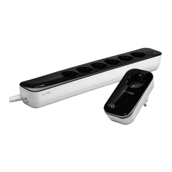
PowerNode Overview The GreenWave Reality PowerNode is a smart outlet adapter that connects your devices to electrical outlets and your GreenWave Reality energy management system so that you can monitor and control your devices’ power usage remotely through a Web browser or smartphone application. PowerNodes are available with a one-port or multi-port configuration. - Page 5 PowerNode plug: Prongs that you plug into your electrical outlet. PowerNode port: Port where you plug in your device. Room color selector: Wheel that you rotate you specify the associated room color. Network button: Button that you press to sync PowerNode with Gateway. Activity indicator and power on/off button.
- Page 6 Room Colors Your PowerNode has a corner wheel with colored numbers to represent the room or device that the PowerNode is powering. Set the PowerNode to the colored number you want to use to identify the room or device (this is referred to as the “room color”). For example, you can set the room color to blue.
- Page 7 Indicators Your PowerNode has an indicator that displays any of the following patterns and colors to show you its current status: Two rotating green bars: PowerNode Off (no color): All PowerNode ports connected to is in inclusion mode to connect with the Gateway are off.
-
Page 8: Installation
Installation Before you install your PowerNode and devices, make sure that your GreenWave Reality Gateway is already connected to your energy management system and operating (refer to the instructions that came with your Gateway). There are four basic steps to install your PowerNode and devices: Set the PowerNode room color. - Page 9 1. Set the PowerNode Room Color Set the PowerNode to the colored number you want to use to identify the room or device (this is referred to as the “room color”). The room color selection is strictly to help you identify the room when you monitor and control its power usage.
- Page 10 4. Plug in the Device and Turn on the PowerNode Plug the device you want to power into the PowerNode port. Turn the PowerNode on by pressing the power button, which will illuminate white to indicate the power is on. Turn the device on. The device is now part of your GreenWave home network.
- Page 11 PowerNodes if their radio signals are blocked by obstacles such as large metal panels or walls containing wire mesh. When placing these devices in your home, imagine invisible lines connecting between them. Try to keep these lines clear from obstruction as much as possible. Also place your PowerNodes at least 1.5-3 feet (.5-1 meters) above floor level to promote reception.
-
Page 12: Common Z-Wave Tasks
Common Z-Wave Tasks The GreenWave Reality PowerNodes communicate wirelessly with the Gateway by use of Z-Wave mesh networking, which is a robust connection technology designed for home automation with security and privacy in mind. The more Z-Wave compatible devices installed in your home, the better coverage your private GreenWave Reality energy management system will have. -
Page 13: Network Exclusion Process
If you attempt to include a PowerNode from another energy management system with an “alien” Gateway, the inclusion will fail and the indicator bars will flash rapidly. To complete the process you must perform the following steps: Plug the PowerNode into an electrical outlet. Locate the network button on the PowerNode. - Page 14 A PowerNode that has been previously used with a different Z-Wave network must have its association (homeID) with the other network removed before you can connect it to your GreenWave Reality energy management system. This process is called “exclusion” and requires two steps: one that must be performed with the Gateway and then one that is performed with the PowerNode.
-
Page 15: Factory Reset Process
Your PowerNode is now free of its former association, and you can perform an inclusion process to include it in your GreenWave Reality energy management system (refer to the “Network Inclusion Process” section above). -
Page 16: Safety Information
Safety Information Indoor Use Only Your PowerNode should be used only in dry, indoor locations. Do not use your PowerNode in high-humidity locations such as greenhouses, saunas, washrooms, or patios. Do not use your PowerNode in locations where it can get wet such as near aquariums or running water. Do Not Disassemble Your PowerNode has no user-serviceable parts inside. - Page 17 Arrange for Service if Needed Should you encounter any problems with your PowerNode, turn the device off by unplugging it from the electrical outlet. Contact Customer Service to arrange for repair at a certified service location under the following conditions: When the power cable or plug is damaged or frayed If the product has been exposed to rain or water If the product casing has been damaged...
-
Page 18: About Greenwave
LED lighting. GreenWave Reality is led by a diverse team of proven leaders with global experience. NORTH AMERICA... - Page 19 Wireless Network Features Z-Wave Radio Frequency: 868.42MHz Z-Wave Maximum Inter-node Range: 30m (measured with line of sight, no obstacles, and height of devices above floor >1m) GreenWave Reality DeviceDNA: v1.0 Z-Wave Command Classes Certified Binary Switch Power Meter Multichannel Firmware Metadata...
- Page 20 (Back Cover)
Need help?
Do you have a question about the PowerNode NP160-F and is the answer not in the manual?
Questions and answers