Advertisement
Quick Links
Advertisement

Related Manuals for SCV KJR-120F

Summary of Contents for SCV KJR-120F
- Page 1 WIRED CONTROLLER MINI CHILLER USER MANUAL KJR-120F AIR CONDITIONING...
- Page 2 “Original instructions” ...
- Page 3 Chiller wired controller 1.1 Mini chiller wired controller: KJR-120F 1.1.1Specifications power adapter Model Description Touch key and backlight function 120F 230-240V~50Hz Input Voltage 10V AC Operating environment -15º C~+43º C temperature Operating RH RH 40%~RH 90%...
-
Page 4: Button Introduction
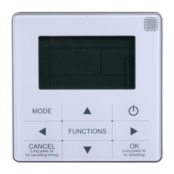
Chiller wired controller 1.1.2 Button introduction MODE FUNCTIONS (Long press 3s (Long press 3s for cancelling timing) for unlocking) Item Description Item Description Operation icon Water temperature Mode area ON/OFF key Water temperature Right, left key Timer ON/OFF OK key Function icon Function key On-line unit qty. - Page 5 Chiller wired controller 4. Timing ON/OFF indication Indicate the timer information; 5. Function icon; 1) Computer Display when connects to computer. 2) Conflict Displays when the unit operation forced cooling mode. 3) Maintenance Displays when the unit is needed. Press″MODE″ key for 3 seconds to cancel the icon and timing will restart until next maintenance.
- Page 6 Chiller wired controller 6. On-line unit qty. indication: Under normal status display the quantity of the units connected to the wired controller; under check status display the device serial number. 7. Water level indication: The reserved icon 8. Clock: Under normal status display clock; during timer setting it displays the setting timing time. 9.
- Page 7 Chiller wired controller 13. Function key: Setting water temperature, timing and clock etc; Press FUNCTION key for 3 seconds to enter check status, setting unit number and forced open water pump. 14. Add, Reduce key: Move up or move down values of temperature, timing etc. 15.
- Page 8 Chiller wired controller Operating mode setting Press ―MODE‖ key to choose operation mode. The setting mode will change as the following order each time the key is pressed: → → Press ―OK‖ key or wait for 7 seconds to confirm. During the setting process, pressing the ―CANCEL‖ key to exit without saving.
- Page 9 Chiller wired controller Setting water temperature: Method 1: Press the ▲ or ▼ to adjust the water temperature under main interface. Press OK key or wait for 7 seconds to confirm. Method 2: Setting water temperature in function parameter: Press FUNCTIONS key under main interface once to enter water temperature setting interface.
- Page 10 Chiller wired controller 1. Timer setting: 3 timing periods can be set on the wire controller: Timer 1, Timer 2, and Timer 3. These 3 timers can control the main unit to be turned ON and OFF 3 times at most during a day. Setting method: press ―FUNCTIONS‖...
- Page 11 Chiller wired controller 4. At this time the mode icon will flash, it means the current setting is the running mode in the Timer 1 , press the ▲ or ▼to adjust, press ► key when finished, the LCD will display as the following: TIMER 5.
- Page 12 Chiller wired controller 7. Example of Timing setting: Main page Press ―FUNCTIONS‖ key twice to enter hour setting interface of ―Timer 1 On‖ Press the ―▲‖ or ―▼‖ key to set the hour number of ―Timing 1 On‖ to be 07 Press ―...
- Page 13 Chiller wired controller Check timing information: to check the timing which has been set, press◄ or ► key under main page, the ―On‖ and ―Off‖ time of Timer1, Timer 2 and Timer3 will be displayed in turns. Cancel timing: Press ―CANCEL‖ key for 3 seconds, then all the effective timing periods will be cancelled. Notes: 1.
- Page 14 Chiller wired controller Unit number setting Press the FUNCTIONS key 4 times to enter the unit number setting. Press ▲ or ▼ to adjust the unit number. Press OK key when finished or wait for 7 seconds to confirm. During the setting process, pressing the CANCEL key to exit without saving.
- Page 15 Chiller wired controller synchronizing with the unit( If forcing water pump function is still on-going, the controller keeping showing its status). d. The outdoor unit does not response after activating the forcing water pump function, (e.g.: forcing water pump function cannot be activated under forcing heating in stand-by mode), the function will be automatically stopped if it is not activated within 5 minutes.
- Page 16 Chiller wired controller Check content Description When in standby mode, water pump mode, displays water inlet temperature. In cooling and heating mode, displays the operating frequency. When defrosting, displays dF; When anti-freezing, displays Pb. When oil returning, displays d0; When remote controlling displays d8. Running model: 0-shutdown, 1-Pump mode, 2-Cooling, 3-Heating, 4-Forced cooling, 5-Forced heating.
- Page 17 Chiller wired controller Error handling icon will flash. If the ―error‖ icon is on, it means the When the unit has error or protection, corresponding unit has error or protection at that time. The last 3 error or protection codes of the unit can be checked.
-
Page 18: Installation Instruction
Chiller wired controller 1.1.4 Installation instruction Circuit of wired controller is the low voltage circuit. Never connect it with a standard 220V/380V circuit or put it into a same Wiring Tube with the circuit. The shield cable must be connected stable to the ground, or transmission may fail. ... - Page 19 Chiller wired controller 2. Wiring sketch 3. Wiring figure 1) During installation, make sure correctly wiring the 5 wiring terminals of the wire controller: A, B connect to output terminal of adapter; P, Q, E should connect to the P, Q, E terminals of the wiring socket in the electric control box through 3-core shielded wire.
- Page 20 Chiller wired controller 4. Back cover installation 1) Use straight head screwdriver to insert into the buckling position in the bottom of wire controller, and spin the screwdriver to take down the back cover. (Pay attention to spinning direction, otherwise will damage the back cover!) Buckling position...
- Page 21 Chiller wired controller 4) Adjust the length of two plastic screw bars in the accessory to be standard length from the electrical box screw bar to the wall. Make sure when install the screw bar to the electrical box screw bar, make it as flat as the wall.
- Page 22 Chiller wired controller When under installation, reserve certain length of the connecting wire for convenient to take down the wired controller while during maintenance. Left down side wire outlet 2) Embedded 86 electrician box wiring 3) Shielded wiring...
- Page 23 Chiller wired controller Avoid the water enter into the wired remote controller, use trap and putty to seal the connectors of wires during wiring installation. 5. Front cover installation After adjusting the front cover and then buckle the front cover; avoid clamping the communication switching wire during installation.
-
Page 24: Technical Support
NOTE CONCERNING PROTECTION OF ENVIRONMENT This product must not be disposed of via normal household waste after its service life, but must be taken to a collection station for the recycling of electrical and electronic devices. The symbol on the product, the operating instructions or the packaging indicate such disposal procedures.
Need help?
Do you have a question about the KJR-120F and is the answer not in the manual?
Questions and answers