Advertisement
Quick Links
INSTALLATION
MANUAL
W12
W11
FOR
INTRINSICALLY
SAFE CIRCUITS
ONLY
"i"
US Version
Horn
Antenna
Gauge
Still Pipe
Gauge
Copyright © June 1995
Saab Marine Electronics AB
W12
W11
FOR
INTRINSICALLY
SAFE CIRCUITS
ONLY
"i"
Parabolic
Antenna
Gauge
W12
W11
FOR
INTRINSICALLY
SAFE CIRCUITS
ONLY
"i"
LPG/LNG
Gauge
Advertisement

Summary of Contents for Saab Marine Electronics TankRadar L/2
- Page 1 INSTALLATION MANUAL US Version INTRINSICALLY SAFE CIRCUITS ONLY INTRINSICALLY SAFE CIRCUITS ONLY "i" "i" Parabolic Horn Antenna Antenna Gauge Gauge INTRINSICALLY SAFE CIRCUITS ONLY "i" Still Pipe LPG/LNG Gauge Gauge Copyright © June 1995 Saab Marine Electronics AB...
-
Page 2: The Manuals Available For Tankradar L/2 Are
(COS) to configure the system. See the OPI Operator’s Manual or the COS Operator’s Manual for detailed explanation. The OPI Operator’s Manual describes how to operate the TankRadar L/2 System using the Operator’s Interface software on a personal computer. The Operator’s Manual for OPI/2 describes Operator’s Interface with the optional inventory functions included, designated OPI/2. -
Page 3: Table Of Contents
Installation Manual Contents The manuals available for TankRadar L/2 are ..........2 Denominations and abbreviations used in this manual: ......6 Introduction to the TankRadar L/2 System ........7 Safety ....................10 Intrinsic Safety .................. 10 Explosion Proof................. 11 Specific FCC Requirements (US market only) ......11 Description of the Radar Tank Gauges ......... - Page 4 12.3 Grounding ..................54 12.4 Electrical Installation of the Radar Tank Gauge, RTG ....54 12.4.1 The Non-Intrinsically Safe Connection (W11) ......54 12.4.2 The Intrinsically Safe Connection (W12) ......... 54 Saab TankRadar L/2 US Version. Seventh edition, June 1995...
- Page 5 System Configuration ..............58 14.2 System Master .................. 58 14.3 Plant Host Computer System (Plant DCS) ........58 14.1.3 Tank Data ..................58 Required System Information Form ......... Appendix 1 Index ....................Index 1 Saab TankRadar L/2 US Version. Seventh edition, June 1995...
-
Page 6: Denominations And Abbreviations Used In This Manual
A device for emitting and receiving micro- waves. Resistance Temperature Detectors Radar Tank Gauge Transmitter Head Tank Radar L (First generation) TRL/2 Tank Radar L/2 Volts Alternating Current Volts Direct Current Saab TankRadar L/2 US Version. Seventh edition, June 1995... -
Page 7: Introduction To The Tankradar L/2 System
Installation Manual Introduction to the TankRadar L/2 System The TankRadar L/2 System is a monitoring and control system for tank level gauging. The system can interface various sensors, such as temperature and pressure sensors, for complete inventory control. There is a distributed intelligence in the various units of the sys- tem. - Page 8 Sensors Temperature Sensors Figure 1.2. Example of a general configuration of a TankRadar L/2 System. All the measured data is presented to the operator by the Operator’s Interface, which in its complete version contains inven- tory functions. A plant host computer can be connected for further processing of data.
- Page 9 Installation Manual The basic parts of the TankRadar L/2 System are: The Radar Tank Gauge, RTG, is an intelligent explosion protected instrument for measuring the level of a product inside a tank. Four different Tank Connection Units can be attached in order to satisfy a variety of different applications.
-
Page 10: Safety
Installation Manual Safety TankRadar L/2 equipment is often used in areas where flammable materials are handled and where an explosive atmosphere may be present. To protect both the plant and the personnel, precautions must be taken to ensure that this atmosphere cannot be ignited. -
Page 11: Explosion Proof
Installation on a non-metallic tank is not certified, and is not allowed. The FCC certificate for TankRadar L/2 requires that the tank is closed as far as emitted radio energy is concerned. Tanks with open manholes, external-floating-roof tanks without still pipes etc. -
Page 12: Description Of The Radar Tank Gauges
SAFE CIRCUITS ONLY "i" "i" "i" LPG/LNG Still Pipe Horn Parabolic Gauge, Antenna Antenna Gauge, RTG 2960 Gauge, Gauge, RTG 2940 RTG 2920 RTG 2930 Figure 3.1 shows the Transmitter Head Saab TankRadar L/2 US Version. Seventh edition, June 1995... -
Page 13: Electronic Unit
12-wire lead seal Not required Required 3 inputs + 2 outputs Table 3.1. The table describes what is required when the optional Slave DAU and/or the optional Current Loop Card are included. Saab TankRadar L/2 US Version. Seventh edition, June 1995... -
Page 14: Power Supply To The Radar Tank Gauge
Do not open while enrgized. Ne pas ouvrir sous tension. connecting power to CAUTION: To prevent ignition of hazardous A division of Saab Marine Electronics AB atmospheres disconnect the device from th MADE IN SWEDEN the Electronic Unit. 3.1.4... -
Page 15: Current Loop Card, Clc (Option)
EN50018 and EN50020 Europe) Power Supply 115 or 230 VAC, +10% to -15%, 50-60 Hz, max. 80 W Field bus TRL/2 Bus (FSK, half duplex, two wires, galvanically iso- lated, 4800 Baud) Saab TankRadar L/2 US Version. Seventh edition, June 1995... -
Page 16: Description Of The Horn Antenna Gauge, Rtg 2920
(2.7 to 66 ft.) Pressure -0.5 to 2 bar Total weight Appr. 20 kg (44 lbs.) Socket size Min. 8" Weather Protection Hood Transmitter Head Closing Cone Figure 3.6 shows the Horn Antenna Gauge. Saab TankRadar L/2 US Version. Seventh edition, June 1995... -
Page 17: Description Of The Parabolic Antenna Gauge, Rtg 2930
Appr. 25 kg (55 lbs.) Socket size Min. 20" Weather Protection Hood Transmitter Head Closing Inclination Adaptor Device Flange Parabolic Antenna Reflector Feeder 0.45 m Figure 3.7 shows the Parabolic Antenna Gauge. Saab TankRadar L/2 US Version. Seventh edition, June 1995... -
Page 18: Description Of The Still Pipe Gauge, Rtg 2940
6", 8", 10" or 12". See table 10.1 for information on schedules. Weather Protection Hood Waveguide Unit Waveguide Connection Transmitter Head Stand Transition Cone Sealing Still pipe Figure 3.8 shows the Still Pipe Gauge. Saab TankRadar L/2 US Version. Seventh edition, June 1995... -
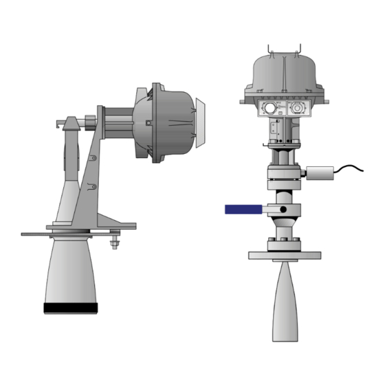
Page 19: Description Of The Lpg/Lng Gauge, Rtg 2960
Head INTRINSICALLY Pressure SAFE CIRCUITS ONLY "i" Transducer Housing Valve Lower Flange 6" Existing pressure Pipe Cone vessel flange Figure 3.9 shows 4" or ø100 mm the LPG/LNG Still Pipe Gauge. Saab TankRadar L/2 US Version. Seventh edition, June 1995... -
Page 20: Description Of The Data Acquisition Units
Connect temperature sensors Connect Reference Resistor to terminals 43, 44 and 45. Figure 4.2 shows the wire terminals for the temperature sensors. Saab TankRadar L/2 US Version. Seventh edition, June 1995... -
Page 21: Selecting The Temperature Range
The switch can be locked and sealed in the write inhibit position using a wire through the clevis pins. See figure 6.3. Saab TankRadar L/2 US Version. Seventh edition, June 1995... -
Page 22: Common Installation Data For Both Daus
Ambient temperature -40° to +65°C Ceq = 0 Leq = 0 Serial no: Saab Tank Control A division of Saab Marine Electronics AB MADE IN SWEDEN For intrinsically safe circuits only Cable Outputs Figure 4.4 shows the Slave Data Acquisition Unit. -
Page 23: Description Of The Independent Data Acquisition Unit
See figure 4.6. Figure 4.6. Plug connector in appro- priate position for normally open or normally closed operation of the relay. Saab TankRadar L/2 US Version. Seventh edition, June 1995... -
Page 24: Installation Data For Dau 2130
15 V, 10 mA). Cable to PC Supplied by Saab Tank Control Explosion protection None 0.115 m Conn. to TRL/2 Conn. Field Bus to PC Figure 5.1 shows the Field Bus Modem. Saab TankRadar L/2 US Version. Seventh edition, June 1995... -
Page 25: Description Of The Field Communication Unit, Fcu 2160
Note: The wire terminals 1 and 3 respectively 2 and 4 on FCM board connector are parallel connected. See installation drawing. TRL/2 Bus Interface boards, FCM boards Figure 6.1 shows the bus ports on the Jumper for Field Communica- RS-232C tion Unit. Saab TankRadar L/2 US Version. Seventh edition, June 1995... -
Page 26: Fcu Enclosure
6.3. Reset switch Write inhibit 115 V Write enable Figure 6.3. Write enable/inhibit switch. Saab TankRadar L/2 US Version. Seventh edition, June 1995... -
Page 27: Installation Data For Fcu 2160
32 DAUs 0.28 m TankRadar L/2 Field Connection Unit Type FCU 2160 Serial no: Saab Tank Control A division of Saab Marine Electronics AB MADE IN SWEDEN Ground Connection Cable Outputs Figure 6.4. The Field Communication Unit. Saab TankRadar L/2... -
Page 28: Description Of The Junction Boxes
Description of the Junction Boxes Saab Tank Control can supply a series of junction boxes for the connection of the various units in the TankRadar L/2 system. Junction Box JB 8 for Connection of RTG to Slave DAU The JB 8 should only be used for intrinsically safe connections. It is used when a Slave DAU is located more than 1.6 m away from the... -
Page 29: Junction Box Jb 16 For Connection To Rtg And Independent Dau
Ceq = 0 Leq = 0 See service manual Listed 9390 Ambient temperature -40° to +65°C Serial no: Saab Tank Control A division of Saab Marine Electronics AB MADE IN SWEDEN For intrinsically safe circuits only Signal JB 16 Figure 7.3 shows... -
Page 30: Connect To The Fcu For Quick Updates
Interface Calculated data: Volume, Mass, Density, etc. TRL/2 Group Bus Measured data: Level, Temperature, Pressure, etc. Figure 8.1 shows two different ways of connecting a host computer to the TRL/2 system. Saab TankRadar L/2 US Version. Seventh edition, June 1995... - Page 31 See Service Manual for instructions. System is started up by customer (after completed training) or a Saab Tank Control Representative according to Service Manual. Send Commissioning Check List to Saab Tank Control. Saab TankRadar L/2 US Version. Seventh edition, June 1995...
-
Page 32: Requirements On The Installation Of The Radar Tank Gauges
Antenna axis axis 30° radar 30° radar beam beam Vertical Vertical plumb plumb line line Figure 10.1 shows 4° ± 1° the free space re- quirements for the Horn Antenna Gauge. Saab TankRadar L/2 US Version. Seventh edition, June 1995... -
Page 33: Socket Requirement
In doubtful cases, please contact Saab Tank Con- trol or one of its representatives. 10.1.2 Socket Requirement Maximum height of socket is 330 mm. Socket height max. 330 mm Figure 10.2. Saab TankRadar L/2 US Version. Seventh edition, June 1995... -
Page 34: Requirements For Parabolic Antenna Gauge, Rtg 2930
W A L W A L T A N K T A N K Figure 10.3 shows the requirements on the flange for RTG 2930 with and without the Inclina- tion Device. Saab TankRadar L/2 US Version. Seventh edition, June 1995... -
Page 35: Free Space Requirement
For evaluation contact Saab Tank Control. 5° 5° Free passage Vertical plumb line Antenna axis 1.5° Figure 10.2 shows the free space requirements for RTG 2930. Saab TankRadar L/2 US Version. Seventh edition, June 1995... -
Page 36: Flange Requirements
Figure 10.6. The gauge can be mounted on a manhole cover. 10.2.4 New Tanks At new installations the distances from the tank wall to the an- tenna axis should be 0.8 m or larger. Saab TankRadar L/2 US Version. Seventh edition, June 1995... -
Page 37: Socket Requirements
Socket Min 1.0 m height to product surface 0.6 m 5° Min 5° Min Ø 455 mm Vertical Plumb Line Figure 10.7 shows the requirements on the socket to RTG 2930. Saab TankRadar L/2 US Version. Seventh edition, June 1995... -
Page 38: Requirements For The Still Pipe Gauge, Rtg 2940
The flange must be horizontal within ±2°. W A L T A N K Figure 10.8. The flange must be horizontal within ± 2 ° . Saab TankRadar L/2 US Version. Seventh edition, June 1995... -
Page 39: New Tanks
The height of the free space requirement depends on which Transition Cone that is used. The larger Transition Cones require higher free space. Saab TankRadar L/2 US Version. Seventh edition, June 1995... -
Page 40: Requirements For The Lpg/Lng Gauge, Rtg 2960
Two or three reference pins installed at the top, the bottom and the middle of the pipe. This system is used when it is not possible to have an epoxy Reflector Plug in the tank. Saab TankRadar L/2 US Version. Seventh edition, June 1995... -
Page 41: System With Reference Pin And Reflector Plug
Radar Tank Gauge so that it measures cor- rectly all the way up to the maximum level. See figure 10.9. INTRINSICALLY SAFE CIRCUITS ONLY "i" Min 800 mm to product surface Figure 10.9 shows an extension pipe. Saab TankRadar L/2 US Version. Seventh edition, June 1995... -
Page 42: Mechanical Installation Of The Radar Tank Gauges
Assembly into the nozzle. Tighten the flange onto the customer’s flange using customer supplied screws and nuts. Check that the socket height is less Cone and flange assembly than 330 mm. Customer's gasket Customer's flange Saab TankRadar L/2 US Version. Seventh edition, June 1995... - Page 43 SAFE CIRCUITS ONLY and washers "i" Mount the Weather Protection Hood Mount Weather and secure with locking pins. Protection Hood and secure with locking pins Mounting INTRINSICALLY SAFE CIRCUITS ONLY pins "i" Saab TankRadar L/2 US Version. Seventh edition, June 1995...
-
Page 44: Installation Of The Parabolic Antenna Gauge, Rtg 2930
"i" Feeder. Mount the Antenna Feeder to Closing the Closing, entering the guide pin Two O-rings into its corresponding hole. Fit the Four M10 four nuts and tighten. nuts Antenna feeder Saab TankRadar L/2 US Version. Seventh edition, June 1995... - Page 45 Transmitter Head Tank center Ridges Tank Open the manhole cover. Fit the Parabolic Reflector onto the Antenna Feeder. Fit and tighten the three Antenna screws. feeder Three M6 Parabolic screws reflector Saab TankRadar L/2 US Version. Seventh edition, June 1995...
- Page 46 Fit the Weather Protection Hood onto Mount Weather the two pins of the Transmitter Protection Hood Head. and secure with locking pins Mounting INTRINSICALLY SAFE CIRCUITS ONLY pins "i" Saab TankRadar L/2 US Version. Seventh edition, June 1995...
-
Page 47: Installation Of The Still Pipe Gauge, Rtg 2940
Stand is O-Ring mounted onto the flange. Mount the Stand onto the Cone and tighten the four screws. Stand Four screws M16-screw Flange with spherical washers Cone Saab TankRadar L/2 US Version. Seventh edition, June 1995... - Page 48 Head properly. Fit and tighten the Head M10 nuts. The Waveguide Unit will not be in a Cables fixed position until the Transmitter pointing Head has been tightened to the down Stand. Saab TankRadar L/2 US Version. Seventh edition, June 1995...
- Page 49 Stand and mount the 2 x M6 Stop screws Weather Protection Hood onto the Note: Tighten top four pins. screw first Fit the two mounting pins for the Weather Protection Hood Saab TankRadar L/2 US Version. Seventh edition, June 1995...
-
Page 50: Installation Of The Lpg/Lng Gauge, Rtg 2960
Four M6 screws Pipe Cone Mount the Spring Sleeve into the Spring baser of the Transmitter Head. Turn Sleeve the Spring Sleeve so that it fits into one of the notches. Saab TankRadar L/2 US Version. Seventh edition, June 1995... - Page 51 Align! The tank is now sealed and can, as far as Saab Tank Control equipment Customer is concerned, be pressurized. Notch indicating Flange the direction of Align! the Reference Pins Reference Saab TankRadar L/2 US Version. Seventh edition, June 1995...
- Page 52 Lower Flange Fit the Weather Protection Hood onto Mount Weather the mounting pins of the Transmitter Protection Hood Head. and secure with locking pins Mounting INTRINSICALLY SAFE CIRCUITS ONLY pins "i" Saab TankRadar L/2 US Version. Seventh edition, June 1995...
-
Page 53: Electrical Installation
1.6 V 0.8 V 200 m 660 ft. 6.3 V 3.2 V 3.2 V 1.6 V 500 m 1640 ft. 16 V Table 12.1. Grey areas show too high voltage drop. Saab TankRadar L/2 US Version. Seventh edition, June 1995... -
Page 54: Cabling For Trl/2 Bus
A flexible protective hose for the wires is delivered with the Bar- rier Unit or the Current Loop Card, or with the Transmitter Head if the units have been factory installed. For reasons of electromag- Saab TankRadar L/2 US Version. Seventh edition, June 1995... -
Page 55: Electrical Installation Of The Data Acquisition Unit, Dau
Four non-intrinsically safe relay outputs are available with two wires per relay. This option has to be specified in the Required System Information Form. The relays are connected through the lead seal W22. Saab TankRadar L/2 US Version. Seventh edition, June 1995... -
Page 56: Electrical Installation Of The Field Bus Modem, Fbm 2170
The RS-232C connection can be made with 3 wires from the PC to the Field Communication Unit. The area must be at least 0.25 mm (AWG 24 or similar). The maximum length of the RS-232C connec- tion is 30 m. Saab TankRadar L/2 US Version. Seventh edition, June 1995... -
Page 57: List Of Drawings
9240002-924 Electrical Installation RTG + Current Loops + DAU 9240002-925 Electrical Installation RTG + Current Loops + Display 9240002-930 Electrical Installation RTG + Current Loops + DAU 9240002-936 Electrical Installation FCU RS-485 - Host Computer Saab TankRadar L/2 US Version. Seventh edition, June 1995... -
Page 58: Description Of The Required System Information
The Tank Reference Point should be the ullage plug which will be used for hand dipping. The Tank Connection Type has to be specified as either Horn Antenna, Still Pipe, Parabola or Saab TankRadar L/2 US Version. Seventh edition, June 1995... - Page 59 Please note the heights of the Resistance Tem- perature Detectors in the tables on pages 6-8 in the appendix. See also figure 14.1 below. INTRINSICALLY SAFE CIRCUITS ONLY "i" Figure 14.1. Installation of DATUM temperature LEVEL sensors. Saab TankRadar L/2 US Version. Seventh edition, June 1995...
- Page 60 Installation Manual This page is intentionally left blank. Saab TankRadar L/2 US Version. Seventh edition, June 1995...
-
Page 61: Required System Information Form
Units, Field Communication Units, Field Bus Modems, Operator’s Interface etc. Note: See chapter 9 in the Installation Manual when completing the form. Copyright © June 1995. Saab Marine Electronics AB Saab TankRadar L/2 Appendix-1 US Version. Seventh edition, June 1995... -
Page 62: System Information
Plant DCS (Plant Host Computer): Type and make (manufacturer) of computer: Type of communication: Communication protocol: Connected to FCU's or to Operator's Interface: Connection to TRL-System: Processor Unit Serial Number: Saab TankRadar L/2 Appendix-2 US Version. Seventh edition, June 1995... - Page 63 Required System Information Form Tank Data Tank Tank Temp. Tank RTG Type Name Product Over Height (2920, -30, Pressure Approx. -40 or -60) Saab TankRadar L/2 Appendix-3 US Version. Seventh edition, June 1995...
- Page 64 Number Flange Pipe Inner Tank Wall Height Inner Slots/ of Slots/ Pressure Diameter (mm) (mm) Diam. Holes Holes Rating (Mark (mm) (Ø or per meter with X) 4" in mm) Saab TankRadar L/2 Appendix-4 US Version. Seventh edition, June 1995...
- Page 65 Conn. to Inde- Number Type of Other Digital Local Name pendent Temp. Inputs: Outputs Readout name or or Slave Temp. Sensors: Normally Display number: DAU: Sensors: ON or (Yes/No) OFF: Saab TankRadar L/2 Appendix-5 US Version. Seventh edition, June 1995...
- Page 66 Required System Information Form Tank Data Specific requirements to fulfill FCC rules (Only for US markets) Any permanent Any occasional Metallic tank Tank Name openings openings on tank (Yes/No) (Yes/No) (Yes/No) Saab TankRadar L/2 Appendix-6 US Version. Seventh edition, June 1995...
- Page 67 Required System Information Form Temperature Sensor Installation INTRINSICALLY SAFE CIRCUITS ONLY "i" DATUM LEVEL Saab TankRadar L/2 Appendix-7 US Version. Seventh edition, June 1995...
- Page 68 Required System Information Form Installation of Temperature Sensors (Cont.) Resistance Temperature Detectors Tank Name Saab TankRadar L/2 Appendix-8 US Version. Seventh edition, June 1995...
-
Page 69: 4 Saab Tankradar L/2
Required System Information Form Installation of Temperature Sensors (Cont.) Resistance Temperature Detectors Tank Name Saab TankRadar L/2 Appendix-9 US Version. Seventh edition, June 1995... -
Page 70: Index
DAU 2130 ............ 24 Ground ............54 DCS ............29, 58 Grounding........... 54 Digital inputs ..........59 Group Bus ........... 25 Digital or frequency inputs ...... 55 DPS board ........... 23 Saab TankRadar L/2 Index 1 US Version. Seventh edition, June 1995... - Page 71 Junction Boxes ..........28 Field Connection Unit...... 26 Independent DAU ......23 Radar Tank Gauge ......14 LCD-display ..........9 Power supply ..........53 List of Drawings ......... 57 Saab TankRadar L/2 Index 2 US Version. Seventh edition, June 1995...
- Page 72 Slave Data Acquisition Unit DAUs ..........21 Description ........22 Field Connection Unit...... 26 Slave DAU ..........20 Socket Requirements Horn Antenna Gauge....... 33 Parabolic Antenna Gauge ....37 Saab TankRadar L/2 Index 3 US Version. Seventh edition, June 1995...
- Page 73 Installation Manual Notes: Saab TankRadar L/2 Index 4 US Version. Seventh edition, June 1995...