Table of Contents
Advertisement
Quick Links
Advertisement
Table of Contents

Summary of Contents for XTS Video XTS-KBC-100
- Page 1 XTS-KBC - 100 USER‘S MANUAL Multi-Protocol keyboard controller...
-
Page 2: Warning
Warning TO REDUCE THE RISK OF FIRE OR ELECTRIC SHOCK, DO NOT EXPOSE THIS PRODUCT TO RAIN OR MOISTURE. DO NOT INSERT ANY METALLIC OBJECTS THROUGH THE VENTILATION GRILLS OR OTHER OPENINGS ON THE EQUIPMENT. This symbol indicates that dangerous voltage constituting a risk of electric shock is present within this unit. -
Page 3: Table Of Contents
Contents Warning....................1 Contents....................2 Introduction..................3 Installation................... 4 Stand-Alone mode................5 RS-485 network................... 6 Working with the keyboard..............7 Operating..................... 8 PTZ-operation..................9 Cruising functions................10 Sequence setup...................11 Viewing control..................12 Keyboard setup menu................13 Keyboard Setup / Auxiliary Functions..........14 Key- Function Overview...............15 Specification.................. -
Page 4: Introduction
INTRODUCTION The keyboard Intelligent, multiple-protocol keyboard controller is designed for operator to control speed-domes, zoom camera and PTZ device. it‘s ergonomic concept and user-friendly 3-axis controlling stick provide its operator max. usability and performance. With this keyboard controller, you can also easily activate and programming presets, tours and memorized personal references on PTZ devices. -
Page 5: Installation
INSTALLATION Unpacking Please unpack the equipment and make sure all listed items and accessories are included in the box: Keyboard controller Chunk box RJ-11 RS485 connection cable Instruction manual Connection There are 2 RJ-11 connectors on the keyboard for RS-485 control: Master port Slave port 9 ~12V Power supply... -
Page 6: Stand-Alone Mode
STAND-ALONE Stand-Alone / Master-Slave operation This keyboard support 2 operation mode for max. 255 devices connected. Depends on the requirement, you can setup the keyboard for stand-alone or master/ Slave mode: 1. Stand-Alone mode: Only 1 controller keyboard is used for all connected devices. In this operation mode, both connectors ( RS-485-1 and RS-485-2) can be used. - Page 7 MASTER/SLAVE MODE (optional function) 2. Master / Slave mode: For certain installations, multiple-control structure might be required. You can setup the keyboard to Master / Slave mode in order to work with more than 1 keyboard simultanously. In this operation mode, all keyboards have to be connected in a chain, with RS-485-1 for output and RS-485-2 as input ports.
-
Page 8: Rs-485 Network
RS-485 NETWORK Depends on the installation environment, you may have different RS-485 chains connected as a „network“. In order to let your keyboard working properly, please refer to the examples given bellow: Multiple connections to a single port You can connect max. 3 RS485-chains to each port ( in Master / Slave mode: connect only to RS- 485-1 port.) For more chains, you need to use a RS-485-Distributor to expand the connectivity ( Please contact technical personnel or sales representatives for purchasing and further information). -
Page 9: Working With The Keyboard
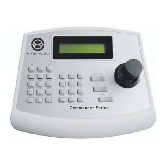
WORKING WITH KEYBOARD Front panel 1. Status & Menu Display: LC-Display with back-light shows current keyboard setting, status and configuration menu. 2. Extended Function keys: activate extended functions, such as extended camera settings and setup 3. Operation keys: Performing default operations such as presets, sequence, camera selection etc. 4. -
Page 10: Operating
OPERATING Turning on the keyboard After plugging in the power, the keyboard will start the initialization and self-test. The LC-Display will show following message: (for about 2 sec.) VERSION V2.06 LCD shows the keyboard‘s firmware version and manufacturing date 2009 / 11 / 05 After about 2 seconds, the keyboard finishes the initialization and is ready to operate : LCD shows the current controlling protocol XTS-2... -
Page 11: Ptz-Operation
PTZ-CONTROL Using the PTZ-Stick You can use the PTZ-Stick to perform pan, tilt and zoom (KB3A only) operation with various speed (depends on the angle the stick has been moved). Move the stick to up or down for the tilt-operation, and move left and right for pan-action. -
Page 12: Sequence Setup
PRESET / CRUISING TRACKS Presets Most Speed-Dome camera and PTZ-devices supports memorizing preset positions. You can use this keyboard to save and call the saved presets. Save a preset-position: move the PTZ device to desired position, then press [N] indicates the current preset and can be any XTS-2 CAM:001 [PRESET] + [N]+ [ENTER]... - Page 13 SEQUENCE/ SCAN/ PATROL No.: index of the points, max. 16 No. Pre Spd Time Pre.: Preset-position assigned for this point, from 1 to 255 Spd: The cruising speed to this point, 1 (lowest ) to 8 (highest speed) Time: duration of the stay in seconds (1 to 99) The cursor now is pointed to n1 ( preset), Use [number]+[Enter] to assign a preset to this point.
- Page 14 FOCUS/ IRIS CONTROL This keyboard provides function keys for accessing zooming, focusing and iris control directly. It is handy to operate them through these keys. In some protocols you might need to enter the manual mode at first before operating. Automatic and manual Focusing: Adjusting the focus of the camera manually.
-
Page 15: Keyboard Setup Menu
KEYBOARD MENU You can change the setting of keyboard from the setup menu. For entering setup, please press the key [Menu] longer than 3 seconds. Use [TELE] for moving to next item, and [WIDE] to move backwards. Press [ENTER] for confirmation. For exiting please press the [MENU]-key, all the changes on settings will be stored. -
Page 16: Keyboard Setup / Auxiliary Functions
AUXILIARY FUNCTIONS 3. LCD Backlight The LC Display supports the backpanel – lightning, which can be helpful in some working environments. 3. LCD Light Use [FAR], [NEAR] to select ON / OFF, use [MENU] for exiting. 4. Key-Tester This keyboard provides a key-tester function for debugging. Enter the Key-Tester and the key board starts waiting for operator‘s 4. - Page 17 SUMMARY-KEY FUNCTION Key-Combination Press once Press 3 sec. x – Remark Range [SEQ] + X + [ENTER] Activate Sequence Setup Sequence 1 – 4 *,** no. X no. X [F1] + X + [ENTER] Auxiliary Function Auxiliary Function 0 – 16 *,** [MENU] Enter device OSD...
-
Page 18: Specification
ADDITIONAL FUNCTION/ SPECIFICATION Auxiliary Functions Function Name Press once Press 3 Sec. Camera Power Back light conpensation Low Illumination mode ( night mode) Camera Display Digital Zoom function Reserved Focusing Automatic Manual Iris Automatic Manual White Balance Automatic Manual Mirror image Mirror Normal Freeze image...
Need help?
Do you have a question about the XTS-KBC-100 and is the answer not in the manual?
Questions and answers