Table of Contents
Advertisement
Quick Links
Advertisement
Table of Contents

Related Manuals for Arris C4

Summary of Contents for Arris C4
- Page 1 C4® CMTS Release 8.3 User Guide STANDARD Revision 1.0 November 2016...
- Page 2 “Software” means ARRIS-licensed software, including updates, and any other enhancements, modifications, and bug fixes thereto, in object code form only, and any full or partial copies thereof. Software is licensed by ARRIS separately or as part of a Product sale.
- Page 3 The licensors of such Embedded Third-party Software shall not be liable or responsible for any of ARRIS’ covenants or obligations under these terms and conditions, and Customer’s rights or remedies with respect to any Embedded Third-party Software under these terms and conditions shall be against ARRIS.
- Page 4 E6000® Converged Edge Router ©ARRIS Enterprises, Inc. 2016 All rights reserved. No part of this publication may be reproduced in any form or by any means or used to make any derivative work (such as translation, transformation, or adaptation) without written permission from ARRIS Enterprises, Inc.
- Page 5 Rateshaping®, Regal®, ServAssure™, Service Visibility Portal™, TeleWire Supply®, TLX®, Touchstone®, Trans Max™, VIPr™, VSM™, and WorkAssure™ are all trademarks of ARRIS Enterprises, Inc. Other trademarks and trade names may be used in this document to refer to either the entities claiming the marks and the names of their products. ARRIS disclaims proprietary interest in the marks and names of others.
- Page 6 Table 1. Revision History Revision Date Reason for Change Rel. 8.3 Preliminary, Issue 1.0 August 2015 Meet Field Soak Ready (FSR) requirements. Rel. 8.3 Standard, Issue 1.0 November 2016 Reissued for General Availability.
-
Page 7: Table Of Contents
Release 5.0 Features ..........................55 Release 5.1.x Features ..........................57 Release 7.0.x Features ..........................59 Release 7.1.x Features ..........................59 Release 7.2.x Features ..........................60 STANDARD Revision 1.0 C4® CMTS Release 8.3 User Guide © 2016 ARRIS Enterprises LLC. All Rights Reserved. -
Page 8: Table Of Contents
WEEE (Waste Electrical and Electronic Equipment) .................. 81 RF Electrical Specifications ..........................82 Network Interfaces ............................. 84 Scalability ................................85 C4 CMTS Chassis ............................85 C4c CMTS Chassis ............................86 STANDARD Revision 1.0 C4® CMTS Release 8.3 User Guide © 2016 ARRIS Enterprises LLC. All Rights Reserved. -
Page 9: Table Of Contents
Main Hardware Components ........................... 104 Module Types and Chassis Slots—Front View ..................105 Chassis — Rear View ..........................106 Installing Modules in the C4 CMTS ........................108 Module Installation Overview ........................108 Installation Diagram ..........................109 Ejector Levers ............................110 Fan Trays ................................ -
Page 10: Table Of Contents
Power Protection Description ........................118 Chassis Maintenance ............................123 Cleaning the Chassis ..........................123 Air Filters ..............................123 Replacing the C4 CMTS Chassis ......................... 123 C4c CMTS Installation Requirements ..................... 125 Safety Precautions ............................126 Lifting Safety ............................. 126 Electrical Equipment Guidelines ......................128 Electrostatic Discharge (ESD) .......................... -
Page 11: Table Of Contents
SCM Upgrade to 1GB RAM (SCM II EM) ......................181 Virtual System Controller ......................... 186 SCM II EM (U) ..............................187 SCM 3 ................................187 STANDARD Revision 1.0 C4® CMTS Release 8.3 User Guide © 2016 ARRIS Enterprises LLC. All Rights Reserved. -
Page 12: Table Of Contents
SCM 3 Operational Interaction ........................ 188 Out-of-Band Management on the SCM 3 ....................188 Upgrading a C4 CMTS to an SCM 3 ......................189 Compact Flash ..............................195 Physical Dimensions ..........................195 Replacing the Compact Flash ........................196 Compact Flash Disk Partitions ........................200 File System Administration ........................ -
Page 13: Table Of Contents
Basic Command Set for Bringing Up a 12U CAM ....................274 24U Cable Access Module (24U CAM) ......................277 Primary Software Function ........................279 LED Status ..............................279 STANDARD Revision 1.0 C4® CMTS Release 8.3 User Guide © 2016 ARRIS Enterprises LLC. All Rights Reserved. -
Page 14: Table Of Contents
Optimizing a Modulation Profile ........................311 Noise and SNR versus Modulation Symbol Rate ..................312 Control Complex Redundancy ....................... 322 Overview ................................322 Add Control Complex ............................323 STANDARD Revision 1.0 C4® CMTS Release 8.3 User Guide © 2016 ARRIS Enterprises LLC. All Rights Reserved. -
Page 15: Table Of Contents
Basic Bring-up Procedure for the C4 CMTS..................... 325 Introduction ..............................325 Chassis Installation and Powering ......................326 HFC Network Connectivity ........................326 IP Network Plan ............................328 Configuration of Back Office Servers ....................... 328 1. Install Cards, Rear PICs, Filler Panels, PCMs, and Fans ................ 331 2. -
Page 16: Table Of Contents
Save the Configuration ..........................363 Local Authentication ..........................363 Managing the CMTS ..........................364 In-band Management..........................364 Out-of-band Management ........................364 Configure the SNMP ..........................365 STANDARD Revision 1.0 C4® CMTS Release 8.3 User Guide © 2016 ARRIS Enterprises LLC. All Rights Reserved. -
Page 17: Table Of Contents
Create CAM Spare Groups ........................382 Fail Back Manually ............................ 383 Deleting a CAM Spare-group ..........................384 Cable-side Configuration ........................386 Overview ................................386 MAC Domains ..............................387 STANDARD Revision 1.0 C4® CMTS Release 8.3 User Guide © 2016 ARRIS Enterprises LLC. All Rights Reserved. -
Page 18: Table Of Contents
Monitoring Interfaces ..........................433 802.1Q VLAN Tagging (Q-tags) .......................... 435 One Q-tag per Network Interface ......................437 Loopback Interfaces for Routing Protocols ....................... 438 STANDARD Revision 1.0 C4® CMTS Release 8.3 User Guide © 2016 ARRIS Enterprises LLC. All Rights Reserved. -
Page 19: Table Of Contents
IS-IS Network Topology — Multi-homing ....................473 Packet Flow Between IS-IS Systems ......................473 Designated Intermediate System (DIS) and Reliable Flooding of LSPs ............ 474 IS-IS Point-to-Point ........................... 475 STANDARD Revision 1.0 C4® CMTS Release 8.3 User Guide © 2016 ARRIS Enterprises LLC. All Rights Reserved. -
Page 20: Table Of Contents
Broadcast Interface Adjacencies ......................480 Advertising MT Reachable Intermediate Systems in LSPs ............... 480 MT IP Forwarding ............................. 480 Configuring MT IS-IS on the C4/c CMTS ....................482 Enable MT IS-IS ............................482 Disable MT IS-IS ............................482 Modify the Default Metric ........................483 Sample Configuration .......................... -
Page 21: Table Of Contents
Route Redistribution for IPv4 Addresses ......................532 BGP Route Maps ............................532 Route Redistribution CLI Commands ....................... 534 IP Route Filtering ............................537 STANDARD Revision 1.0 C4® CMTS Release 8.3 User Guide © 2016 ARRIS Enterprises LLC. All Rights Reserved. -
Page 22: Table Of Contents
Effect of IP Packet Filtering / Subscriber Management on IP Address Limits .......... 574 Per-Interface Configuration ........................575 Default Subscriber Management Settings ....................577 C4 CMTS Debug IP Packet Capture ......................578 IP Filter Related CLI Commands ....................... 580 IP Packet Filtering Configuration Example ....................581 Upstream Drop Classifiers .......................... -
Page 23: Table Of Contents
Show Cable Command ..........................609 Configure Interface Cable-mac ........................ 610 BPI Hybrid Mode Operation ..........................611 Overview ..............................611 BPI+ Enforce ..............................613 CLI Commands ............................614 STANDARD Revision 1.0 C4® CMTS Release 8.3 User Guide © 2016 ARRIS Enterprises LLC. All Rights Reserved. -
Page 24: Table Of Contents
Considerations ............................645 Dynamic Host Configuration Protocol (DHCP) ....................646 DHCP Client .............................. 646 DHCP Server ............................. 646 DHCP Relay Agent ............................ 647 STANDARD Revision 1.0 C4® CMTS Release 8.3 User Guide © 2016 ARRIS Enterprises LLC. All Rights Reserved. -
Page 25: Table Of Contents
Show Commands .............................. 679 Example of Modifying a State Machine ....................682 State Machine Crosschecks ..........................683 Channel Bonding ........................... 685 Channel Assignment ............................685 STANDARD Revision 1.0 C4® CMTS Release 8.3 User Guide © 2016 ARRIS Enterprises LLC. All Rights Reserved. -
Page 26: Table Of Contents
CM Channel Reassignment for AC Power Loss ..................710 CM-STATUS Message ..........................711 Related CLI Commands ..........................711 Observability ..............................712 IPv6 ..............................715 Overview ..............................715 MDF ................................716 STANDARD Revision 1.0 C4® CMTS Release 8.3 User Guide © 2016 ARRIS Enterprises LLC. All Rights Reserved. -
Page 27: Table Of Contents
Neighbor Discovery Proxy for CPE Traffic ....................720 IPv6 over Ethernet ........................... 721 Well-Known Multicast Addresses ......................721 C4/c CMTS Security Features for IPv6 ......................723 IPv6 Configure Commands ..........................724 Neighbor Discovery Commands ....................... 725 Router Advertisements for IPv6 ....................... 727 DHCPv6 Relay Agent .......................... -
Page 28: Table Of Contents
Verifying the Configuration ........................764 IP Video Monitoring and Management ......................771 Current Hour Results ..........................772 CLI Commands for IP Video ..........................774 STANDARD Revision 1.0 C4® CMTS Release 8.3 User Guide © 2016 ARRIS Enterprises LLC. All Rights Reserved. -
Page 29: Table Of Contents
Multicast CAC Description ..........................798 Guidelines for CAC Thresholds in Non-converged System ..............799 Guidelines for CAC Thresholds in Converged System ................800 Configuring CAC ..............................800 STANDARD Revision 1.0 C4® CMTS Release 8.3 User Guide © 2016 ARRIS Enterprises LLC. All Rights Reserved. -
Page 30: Table Of Contents
Security ..............................832 AAA Overview ..............................832 The AAA Model ............................833 Line Interfaces ............................834 AAA Functions Supported by the C4/c CMTS ................... 835 Local Authentication ............................836 RADIUS Authentication ............................. 837 RADIUS Servers and Server Groups ......................837 STANDARD Revision 1.0... -
Page 31: Table Of Contents
Accounting Method Lists.......................... 846 Common CLI Commands for AAA Using TACACS ..................846 Enable TACACS Authentication ........................ 848 Configuring the C4/c CMTS to Enable Password ..................848 TACACS+ Source Interface ..........................852 Operational Concerns ..........................852 Feature Interactions ..........................853 Configuring TACACS+ Source Interface .................... -
Page 32: Table Of Contents
Additional Guidelines ..........................885 Configuring PC 2.0 LAES ........................... 886 Configuration Guidelines .......................... 886 Configure SNMPv3 User View ........................888 Configure Intercept Source Interface ....................... 889 STANDARD Revision 1.0 C4® CMTS Release 8.3 User Guide © 2016 ARRIS Enterprises LLC. All Rights Reserved. -
Page 33: Table Of Contents
Periodic Load Balancing Actions ......................915 Load Balancing Bonded DS and US Modems via DBC ................917 Load Balancing Bonded Modems via DCC ....................919 STANDARD Revision 1.0 C4® CMTS Release 8.3 User Guide © 2016 ARRIS Enterprises LLC. All Rights Reserved. -
Page 34: Table Of Contents
Cable Throttling Command Examples ...................... 936 ARP/ICMP Throttling ............................940 Configure ARP Throttling Commands ...................... 940 Default Configuration for ARP Throttling ....................942 STANDARD Revision 1.0 C4® CMTS Release 8.3 User Guide © 2016 ARRIS Enterprises LLC. All Rights Reserved. -
Page 35: Table Of Contents
Provision In-band Management....................... 953 SNMP ACL ..............................954 IGMP ACLs ................................. 954 Example 1 ..............................955 Example 2 ..............................955 IPv6 ACLs ................................955 STANDARD Revision 1.0 C4® CMTS Release 8.3 User Guide © 2016 ARRIS Enterprises LLC. All Rights Reserved. -
Page 36: Table Of Contents
How to Administer the Host Name and User IDs ..................... 970 Configure a Host Name ..........................970 Syslog Server IPAddress ........................... 971 How to Add and Delete Users ........................... 971 STANDARD Revision 1.0 C4® CMTS Release 8.3 User Guide © 2016 ARRIS Enterprises LLC. All Rights Reserved. -
Page 37: Table Of Contents
Service Flows ............................992 Major Functions ............................992 Quality of Service Parameters MIB ......................993 Service Class Name Configuration ......................996 Service Classes ..............................996 STANDARD Revision 1.0 C4® CMTS Release 8.3 User Guide © 2016 ARRIS Enterprises LLC. All Rights Reserved. -
Page 38: Table Of Contents
Displaying Throughput ........................... 1013 Two Display Formats ............................1013 Display Basic CM QoS Output ........................ 1014 Display Verbose CM QoS Output ......................1015 STANDARD Revision 1.0 C4® CMTS Release 8.3 User Guide © 2016 ARRIS Enterprises LLC. All Rights Reserved. -
Page 39: Table Of Contents
Diagnostic Failure and Recovery ........................1029 Diagnostic Failure ........................... 1029 Recovery ..............................1030 Logging ............................... 1031 Overview ................................. 1031 Event Messages .............................. 1032 Asynchronous Notification Management ....................1032 STANDARD Revision 1.0 C4® CMTS Release 8.3 User Guide © 2016 ARRIS Enterprises LLC. All Rights Reserved. -
Page 40: Table Of Contents
Display Event Logging Overrides ......................1045 Display CLI Access Levels and Priority ....................1045 Display Proprietary Logging Status ......................1046 System Console ............................... 1046 STANDARD Revision 1.0 C4® CMTS Release 8.3 User Guide © 2016 ARRIS Enterprises LLC. All Rights Reserved. -
Page 41: Table Of Contents
Display Local Log Priority ........................1053 Syslog Server ..............................1053 Standard Protocol ..........................1053 Multiple Syslog Servers .......................... 1053 Event Priorities ............................1054 Syslog Facilities ............................1054 STANDARD Revision 1.0 C4® CMTS Release 8.3 User Guide © 2016 ARRIS Enterprises LLC. All Rights Reserved. -
Page 42: Table Of Contents
Fully-Qualified Domain Name (FQDN) ....................1070 Overview ................................. 1070 Limited Support for FQDN Feature ......................1071 Operational Concerns ............................. 1071 CLI Commands..............................1073 FQDN Rejection Scenarios ..........................1075 STANDARD Revision 1.0 C4® CMTS Release 8.3 User Guide © 2016 ARRIS Enterprises LLC. All Rights Reserved. -
Page 43: Table Of Contents
Basic Searching ............................1115 How to Use CLI Filtering ......................... 1115 Show Cable Modem Column Feature ......................1123 Command Parameters ........................... 1123 Help Enhancements ..........................1125 STANDARD Revision 1.0 C4® CMTS Release 8.3 User Guide © 2016 ARRIS Enterprises LLC. All Rights Reserved. - Page 44 Command Line Descriptions ........................ 1127 Alphabetical List of CLI Commands ...................... 3085 Abbreviations ............................. 3171 STANDARD Revision 1.0 C4® CMTS Release 8.3 User Guide © 2016 ARRIS Enterprises LLC. All Rights Reserved.
-
Page 45: Introduction
Software Release 7.1 ARRIS introduced the C4c CMTS which was based on the larger C4 CMTS. The C4c CMTS is a compact version of the full-sized C4 CMTS. Because it measures only 7 rack units (RUs) — half the height of the C4 CMTS, it is ideal for headends with space or environmental limitations. -
Page 46: Purpose
RF cable plant and operating methods. Purpose To provide a comprehensive overview of the C4 and C4c CMTS including reference and procedural information required to manage and control the C4 and C4c CMTS. Conventions Used in this Document This section presents the textual conventions used in this documentation set. -
Page 47: Admonishments
STANDARD Revision 1.0 C4® CMTS Release 8.3 User Guide © 2016 ARRIS Enterprises LLC. All Rights Reserved. -
Page 48: C4/C4C Cmts Features
In December, 2004, the C4 Cable Modem Termination System (CMTS) received DOCSIS® 2.0 requalification by CableLabs® with the new software upgrade designed to support DOCSIS Set-top Gateway (DSG) technology. With this qualification, the C4 CMTS, configured with the higher density 2Dx12U CAM provided the most reliable and scalable C4 CMTS solution available. -
Page 49: Docsis 3.0 Compliance
IPv6 Management of CMs and Forwarding of CPE Traffic Enhanced Operations Support System Interface. The ARRIS C4c CMTS is a compact DOCSIS 3.0 CMTS based on the proven hardware and software of the larger C4 CMTS solution. STANDARD Revision 1.0 C4® CMTS Release 8.3 User Guide... -
Page 50: Fault Detection And Recovery
Interfaces and Protocols Open interfaces and protocols allow seamless integration with existing network management infrastructures. The primary protocols supported by the C4/C4c CMTS include the following: Simple Network Management Protocol (SNMP) — v1, v2c, and v3 DOCSIS 1.1, DOCSIS 2.0, DOCSIS 3.0 (Bronze), and Cadant MIBS ... -
Page 51: Baseline Features And Early Releases
Baseline Features and Early Releases The ARRIS C4/C4c CMTS Release 8.3 aggregated Feature Set is comprised of the Baseline Feature Set, plus the features of software Releases 3.0, 3.3, 4.0, 4.1, 4.2, 5.0, 7.0, 7.1, 7.2, 7.3, 7.4, 8.0, 8.1, the Small Feature Release 8.1.5, 8.2, 8.2.5, and 8.3. -
Page 52: Release 3.3 Features
configure privilege exec level. Release 4.0 Features The following features or improvements have been added for release 4.0: STANDARD Revision 1.0 C4® CMTS Release 8.3 User Guide © 2016 ARRIS Enterprises LLC. All Rights Reserved. - Page 53 Voice call requirements: At least 1,000 MTAs (Multimedia Terminal Adapters) per downstream At least 5,000 BHCAs with completion rate of 99.5% STANDARD Revision 1.0 C4® CMTS Release 8.3 User Guide © 2016 ARRIS Enterprises LLC. All Rights Reserved.
-
Page 54: Release 4.1 Features
Clear the IP filter counters through the CLI Hitless software update PacketCable 1.x Voice call requirements MTAs /downstream (1D) 1000 MTAs/downstream (2D) 1500 MTAs/C4 20000 STANDARD Revision 1.0 C4® CMTS Release 8.3 User Guide © 2016 ARRIS Enterprises LLC. All Rights Reserved. -
Page 55: Release 5.0 Features
Cadant® C4®CMTS Software Upgrade Notes. This file is included on the software CD. In addition to the previously described features and functionality, the following section describes the C4 CMTS feature set for Release 5.0. This includes: Release 5.0 Features... - Page 56 Show Cable Modem Columns. Note: These call capacities assume that the C4 CMTS is equipped with GNAMs. If the chassis is equipped with Ethernet NAMs, the number of MTAs supported is only 10,000. Dynamic Load Balancing — The Dynamic Load Balancing feature automatically moves modems from one upstream channel to another, or from one downstream to another (including from one 2Dx12U CAM to another).
-
Page 57: Release 5.1.X Features
Chapter 2: C4/C4c CMTS Features Secure NTP — A mechanism is provided for authentication of NTP messages. For MSOs who require NTPv4 functionality, including server or peer authorization, the C4 CMTS will only support the NTPv4 symmetric key MD5 secure hash authentication method. - Page 58 DHCP Lease Query Feature Configurability adds a source IP address verification phase to the IP address learning process of the C4 CMTS. This configurable Cable Source Verify feature is intended to eliminate host- initiated corruption of the layer 2 and layer 3 address spaces on the cable network.
-
Page 59: Release 7.0.X Features
Release 7.0.x Features The Release 7.0 C4 CMTS is an integrated DOCSIS 3.0 solution in that it contains both downstream and upstream modules and all associated CMTS components in a single chassis. The following is a list of the new features included in Software Release 7.0.x:... -
Page 60: Release 7.2.X Features
Mixed Annex Support Modem Steering Release 7.3.x Features The following is a list of the new features included in Software Release 7.3.x: STANDARD Revision 1.0 C4® CMTS Release 8.3 User Guide © 2016 ARRIS Enterprises LLC. All Rights Reserved. - Page 61 Supports IPv6 CPE US traffic Supports dual stack CPE Support CM DS filtering traffic IPv4 Support CM US filtering traffic IPv4 Support CPE DS filtering traffic IPv4 STANDARD Revision 1.0 C4® CMTS Release 8.3 User Guide © 2016 ARRIS Enterprises LLC. All Rights Reserved.
-
Page 62: Release 7.4.X Features
DSID Addition and Deletion Counts-based US Load Balancing With Weighting Modem Steering via Attribute Mask Policy-Based Routing 12U Scaling Enhancement STANDARD Revision 1.0 C4® CMTS Release 8.3 User Guide © 2016 ARRIS Enterprises LLC. All Rights Reserved. -
Page 63: Release 8.0.X Features
IS-IS Multi-topology (MT) provides independent topologies for IS-IS routing and is particularly useful when IS-IS is being used both for IPv4 routing and for migration to IPv6 routing. In this software release, the C4 CMTS supports MT #0 (IPv4 unicast) and MT #2 (IPv6 unicast) as described in RFC 5120. -
Page 64: Release 8.1.X Features
FQDN to IP address entry so that the CMTS can obtain the corresponding IP address from the FQDN parameter. Should the source IP multicast address have to change, the MSO would change it on the DNS and the C4 CMTS will then resolve the new address via DNS and re-initiate IGMP joins as needed. -
Page 65: Release 8.1.5 -- Small Feature Release
SCM 3 is being introduced to improve capacity, performance, and materially extend the operation lifespan of the current C4 CMTS. The SCM 3 will not coexist with previous versions of the SCM, SCM II, SCM II EM, or the SCM II EM (U). -
Page 66: Release 8.2 Features
Release 8.2 Features The following is a list of the new features in Release 8.2: STANDARD Revision 1.0 C4® CMTS Release 8.3 User Guide © 2016 ARRIS Enterprises LLC. All Rights Reserved. - Page 67 If a match is found using the secondary (or alternate) shared secret, the modem will be allowed by the C4 CMTS. Enhanced Scaling with Upstream Channel Bonding will implement measures to reduce C4 CMTS system resources consumed by modems using multiple upstreams (MTCM) so that the per-CAM scaling of upstream-bonding modems is increased.
- Page 68 Policy-Based Routing (PBR) Recursive Next Hop will enhance the existing PBR feature to support configuration of a next hop address which is not directly connected to the C4 CMTS. A recursive route look-up will be supported to obtain the next-hop IP address. The RCM will forward the packet using the IP address obtained via look-up instead of the Destination IP in the packet.
-
Page 69: Release 8.2.5 Features
Annex A Mixed Modulation (Q64 / Q256) per F-connector (blocks of 4 channels) will support simultaneous use of 256 QAM modulation and 64 QAM modulation on a single F-connector from the XD-CAM. This functionality is required for STANDARD Revision 1.0 C4® CMTS Release 8.3 User Guide © 2016 ARRIS Enterprises LLC. All Rights Reserved. - Page 70 Chapter 2: C4/C4c CMTS Features Annex A only. The C4 CMTS will support four (4) channels at 64 QAM and four (4) channels at 256 QAM on each of the four (4) F-connector outputs of the XD-CAM. The four (4) 64 QAM channels on each F-connector may be set at a power level 6 dB below that of the 256 QAM channels.
-
Page 71: Release 8.3 Features
(3.0), but will default to the extended value (4.3). BSoD L2 VPN Configuration via CLI implements CLI functionality in the C4 CMTS to allow a modem to be assigned to a specified BSoD L2 VPN without putting the L2VPN TLVs in the modem configuration file. - Page 72 CPE on the cable side of the CMTS. The destination of the broadcast DHCP messages is the DHCP server reached through a Network Side Interface (NSI). DHCP Options (page 647) in the CPE Device Class chapter. STANDARD Revision 1.0 C4® CMTS Release 8.3 User Guide © 2016 ARRIS Enterprises LLC. All Rights Reserved.
- Page 73 For non-voice service flows, this feature will implement a latency-based random packet discard where the latency thresholds and probability of drop will be provisionable. See Per Downstream Latency in the Packet Throttling chapter. STANDARD Revision 1.0 C4® CMTS Release 8.3 User Guide © 2016 ARRIS Enterprises LLC. All Rights Reserved.
-
Page 74: C4/C4C Cmts Specifications
VoIP Call Capacities ................87 Application-related Specifications ............. 89 Overview This chapter will introduce the features and functionality for both the C4 CMTS and the C4c CMTS. This chapter contains the following topics: Descriptive and reference information Physical design information ... -
Page 75: Network Diagram
Chapter 3: C4/C4c CMTS Specifications Network Diagram A cable network system consists of cable modems (CMs) at subscriber premises, a C4/C4c CMTS at the cable plant operations area, a data-over-cable management software suite integrated with the operator's other management systems, and the Hybrid Fiber Coaxial (HFC) cabling that connects it all. -
Page 76: C4C Cmts
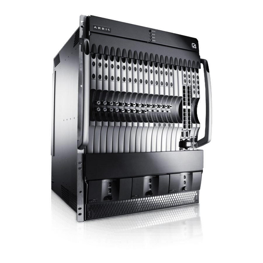
C4 CMTS The following graphic displays the front view of the C4 CMTS. There are a total of twenty-one slots for modules. There are four main types of modules used to equip the slots in the front. These are sometimes referred to as front cards. Smaller modules, called Physical Interface Cards, or PICs, are inserted in each slot from the rear of the chassis. -
Page 77: Slot Numbering Scheme
Slot 19 Slot 17 The slot numbering scheme makes the C4c CMTS compatible with C4 CMTS software. Without this numbering scheme the software would return provisioning errors for cards used in the wrong slots. The CAMs, RCM, SCM, power modules, and Fan Tray Module plus filter are hot-swappable and field-replaceable units. -
Page 78: Limited Support For The 2Dx12U Cam In The C4C Cmts
Mounting Height 24.5" (622 mm) 12.25" (311 mm) Dimensions: Width 17.4" (422 mm) 17.45" (433 mm) Depth 20.0" (508 mm) 22.5" (572 mm) STANDARD Revision 1.0 C4® CMTS Release 8.3 User Guide © 2016 ARRIS Enterprises LLC. All Rights Reserved. -
Page 79: Power
Start-up voltage range Note: If powered down, the C4 and C4c CMTS will not restart successfully if the voltage is not in the range of -44 to - 67.5V DC. This offset from the operating range provides a cushion against multiple possible power cycles. Attempted start-ups at the voltage extremes are subject ot power fluctuations that could result in multiple power cycles and damage to the equipment. -
Page 80: Electromagnetic Compatibility
ETS 300 019 In-use (Class3.1E) Storage (Class 1.2) Transportation (Class 2.3) Thermal — The C4 CMTS meets the following environmental standards: NEBS GR-63-CORE, ETS 300 019 Operating temperature Short term -5 to +55ºC Long term: +5 to +40ºC... -
Page 81: Weee (Waste Electrical And Electronic Equipment)
Directive 2002/96/EC of the European Parliament and of the Council on waste electrical and electronic equipment (WEEE). WEEE could potentially prove harmful to the environment; as such, upon disposal of the C4 CMTS and its components, the Directive requires that this product must not be disposed as unsorted municipal waste, but rather collected separately and disposed of in accordance with local WEEE ordinances. -
Page 82: Rf Electrical Specifications
Chapter 3: C4/C4c CMTS Specifications RF Electrical Specifications The following table lists the downstream RF electrical specifications for the C4 and C4c CMTSs. Table 4. Downstream RF Electrical Specifications Specification 16D or XD CAM Center frequency range supported: 57 - 999 MHz... - Page 83 Modulation types Type 5 TLV: QPSK, 8QAM, 16QAM, 32QAM, and 64QAM Raw bit rate (Max.) 30.72 Mbps RF Input Level (dBmV) -16 to 29 STANDARD Revision 1.0 C4® CMTS Release 8.3 User Guide © 2016 ARRIS Enterprises LLC. All Rights Reserved.
-
Page 84: Network Interfaces
Note: It is not recommended that upstream ranges go beyond +23 dBmV. (See the tables in 24U CAM Upstream Power Level Groups ("24U CAM Upstream Power Level Groups" page 282) for more details on the Upstream Power Level Groups.) Network Interfaces The C4 and C4c CMTSs support the following network interfaces: 10 Base-T (SCM Maintenance Port) ... -
Page 85: Scalability
This leads to lower cost for installation, operations, and maintenance. C4 CMTS Chassis A fully equipped C4 CMTS chassis offering basic service will provide reasonable performance up to the following suggested subscriber limits: 128,000 ARP cache entries ... -
Page 86: C4C Cmts Chassis
32,800 downstreams classifiers 320 simultaneous Service Independent Intercept (SII) taps Chassis with the SCM II EM/EM (U) and SCM 3 board STANDARD Revision 1.0 C4® CMTS Release 8.3 User Guide © 2016 ARRIS Enterprises LLC. All Rights Reserved. -
Page 87: Voip Call Capacities
3. The total number of IPv6 dynamic routes is a combination of OSPFv5 and IS-IS IPv6 routes. VoIP Call Capacities The following Voice over Internet Protocol hardware and call limits apply to both the C4 and C4c CMTSs configured for DSx/DQoS VoIP or PacketCable voice. - Page 88 3,348 Maximum per 16D/XD CAM 26,640 BHCA per upstream channel Maximum per 24U CAM (C4 CMTS only) 16,500 Simultaneous half-calls/downstream channel Simultaneous half-calls/upstream channel Connections per second per chassis Call load performance is based on the following assumptions: Lines per subscriber ...
- Page 89 Complies with the following subset of PacketCable Multimedia Multimedia Specification, PKT-SP-MM-I03-051221: PCMM Gate Control State Synchronization Versioning All traffic profile formats DOCSIS Parameters IKE/IPSec STANDARD Revision 1.0 C4® CMTS Release 8.3 User Guide © 2016 ARRIS Enterprises LLC. All Rights Reserved.
- Page 90 Packet Cable Update of Major/Minor Version for I04 Traffic Profile: Upstream Drop DOCSIS Set-top DOCSIS 2.0 qualification at Cert- Gateway (DSG) wave 32 includes DSG STANDARD Revision 1.0 C4® CMTS Release 8.3 User Guide © 2016 ARRIS Enterprises LLC. All Rights Reserved.
-
Page 91: C4 Cmts General Installation Requirements
Installation Considerations..............99 Rack Mounting the C4 CMTS ............102 Main Hardware Components ............104 Installing Modules in the C4 CMTS ..........108 Fan Trays ..................110 Power Conditioning Module and Cabling ........113 ... -
Page 92: Overview
This chapter provides the operating precautions and installation requirements for the C4 CMTS. Note: Do not make any mechanical or electrical modifications to either the C4 CMTS equipment. If modified, the C4 CMTS may no longer comply with regulatory standards. - Page 93 Chapter 4: C4 CMTS General Installation Requirements To lift the chassis, use two people (one on each side). With on hand, grasp a front handle, and with the other hand, grasp a back handle or grasp the underside of the chassis and lift slowly. Do not twist your body as you lift.
-
Page 94: Electrical Equipment Guidelines
CAUTION: The ports of the C4/C4c CMTS chassis are suitable for connection to intra-building or unexposed wiring or cabling only. The ports of the chassis MUST NOT be metallically connected to interfaces which connect to outside plant (OSP) or its wiring. -
Page 95: C4 Cmts Installation Checklist
Installation involves mounting the unit in a rack, populating slots with client and system modules and Physical Interface Cards (PICs), attaching cables, and configuring software. Follow the instructions in this section when installing the C4 CMTS for the first time. -
Page 96: Tools Required
Digital volt meter Torque wrench Torque Values The following table lists the recommended torque values for selected screws and fasteners of the C4 CMTS. Table 10. Recommended Torque Values in Inch-pounds Fasteners Torque Screws for grounding cable 10.0 +/- 0.5 in-lbs. -
Page 97: Items Not Supplied
Small Form-factor Pluggable (SFP) or a 10G Small Form-factor Pluggable (XFP) to be used with the RCM. For more information, see SFP and SFP Ethernet interfaces. If you plan to operate the C4 CMTS in duplex mode (redundant control complexes), you must purchase one (1) C4 CMTS Router Control Module Crossover Connector (Part Number 722891) along with the two RCMs and two SCMs. - Page 98 ordered a configured chassis. In a configured chassis modules are shipped in their slots. Check the packing slip and verify its contents. If an entire C4 CMTS is ordered, it typically ships with the following items. Use the checklist provided below to verify that the required items are present.
-
Page 99: Module Protection
Installation Considerations Rack Mounting The C4 CMTS is designed to be mounted in a standard 7-foot by 19-inch equipment rack, compliant with EIA RS-310. A total of three chassis can be installed in this equipment rack. Uneven mechanical loading of an equipment rack can be hazardous. Plan the installation so that the weight of the equipment is evenly distributed across the vertical height of the rack. -
Page 100: Power Requirements
CAMs (16) is used. The C4 CMTS draws cooling air in through the front, sides, and back at the bottom of the unit and expels it out the sides and back at the top of the unit. Clear airflow must be maintained in these areas to ensure adequate ventilation. If the C4 STANDARD Revision 1.0... - Page 101 CMTS is installed in a closed or multi-unit rack assembly, the inlet air temperature could exceed the room ambient air temperature and/or the air flow may be reduced. In these cases, the C4 CMTS requires a colder room temperature be maintained to compensate for this type of installation.
-
Page 102: Rack Mounting The C4 Cmts
This grill is the primary heat vent for the chassis. Blocking it can cause overheating and card failure. Allow sufficient clearance for airflow around the chassis. Rack Mounting the C4 CMTS The following steps outline how to rack mount the C4 CMTS. STANDARD Revision 1.0 C4® CMTS Release 8.3 User Guide... -
Page 103: Grounding The Chassis
Grounding the Chassis The C4 CMTS chassis must be properly connected to protective earth ground for safety compliance. There are two places you can connect the protective earth ground wire to the chassis. One is located on the side of the chassis; the other is located on the rear of the chassis between the PCMs (refer to the figure below). -
Page 104: Main Hardware Components
Figure 7: Location of Grounding Terminals Main Hardware Components The C4 CMTS base system contains the following components: C4 CMTS chassis Two Power Conditioning Modules (PCMs) – Power Feeds A & B ... -
Page 105: Module Types And Chassis Slots—Front View
Chapter 4: C4 CMTS General Installation Requirements Module Types and Chassis Slots—Front View The C4 CMTS chassis front contains twenty-one vertical slots labeled 0-20 (from left to right). These slots are equipped for the following modules (sometimes referred to as front cards): One or two System Control Modules ... -
Page 106: Chassis — Rear View
Chapter 4: C4 CMTS General Installation Requirements Slot 16 is equipped with a front filler panel Two RCMs in slots 17 and 18 (these slots can be equipped only with RCMs; slot 17 must be the first equipped.) A ... - Page 107 Between the front and back slots is the midplane of the chassis. The midplane connects the front modules to the rear modules. The midplane is a necessary point of communication for all modules inserted in the C4 CMTS. The midplane is...
-
Page 108: Installing Modules In The C4 Cmts
All unused module slots, front and rear, must be equipped with filler panels. Filler panels are required for proper EMC emission levels and sufficient airflow to properly cool the C4 CMTS system. Failure to cover empty slots reduces the air flow through the chassis and could result in overheating. -
Page 109: Installation Diagram
Chapter 4: C4 CMTS General Installation Requirements 3. Install proper PIC or filler panel in the corresponding rear slot of the chassis. (The RCM does not have a PIC; use a filler panel instead.) Note: If you meet strong resistance when attempting to seat the module, PIC or filler panel, remove it from the chassis and try reinserting it. -
Page 110: Ejector Levers
Fan Trays The C4 CMTS contains three Fan Trays (also called modules) numbered 0, 1, and 2. Each tray contains a front and rear fan. A failing fan is easily identified by the Fan Status LED on the Fan Tray. Maintenance personnel can replace the failed Fan Tray without shutting down the entire system. -
Page 111: High Speed Fan Trays
Chapter 4: C4 CMTS General Installation Requirements High Speed Fan Trays All Release 8.x chassis require high-speed Fan Trays. These trays are labeled "High Speed" on their front plates. Figure 12: Example of High Speed Fan Tray WARNING: To prevent unnecessary equipment damage, the Fan Tray should be installed only in a chassis that is securely mounted in a frame or rack. -
Page 112: Air Filter
Air Filter The C4 CMTS comes equipped with an air filter mounted horizontally just above the fan assemblies and just below the chassis slots. It is important to change the fan filter at least every three months, depending on the air quality on site. -
Page 113: Power Conditioning Module And Cabling
Power Conditioning Module and Cabling The C4 CMTS requires two -48V power feeds, A and B, for redundancy. The source can be an external battery plant or independent AC/DC power supply. In the event that one feed fails or is removed from service for maintenance, the other feed continues to supply power to the C4 CMTS with no interruption in service. - Page 114 The recommended torque for these fasteners is 5.0 ±0.5 inch-pounds. Power Requirements The C4 CMTS must be connected to a protected DC power source that meets the following current requirements: Input voltage: A and B feed from –44V to -72V ...
- Page 115 1. Refer to the figure above and follow the steps below to cable the PCM. 2. Two cables, one red and one blue (each containing two 6 gauge wires, one red and one white) are included with the C4 CMTS. One end of each cable is connectorized and keyed for the power connector on the rear of the chassis.
-
Page 116: Front Panel Access
Chapter 4: C4 CMTS General Installation Requirements 4. On the front power status panel, turn the PCM (to be replaced) off for the appropriate power branch by pushing and holding its power button down. There is an approximate 2-second delay on the power down to avoid accidental shutdowns. - Page 117 Chapter 4: C4 CMTS General Installation Requirements Another small panel is found beneath the lower matching panel. The chassis slot numbers are printed on it; it flips down to allow access to the air filter. Figure 16: C4 CMTS Front Access Panels STANDARD Revision 1.0...
-
Page 118: Power Protection Description
A and B Power Feeds Power is supplied to the C4 CMTS via A and B feeds located at the rear of the unit. The C4 CMTS chassis is protected by two 70-amp breakers located on the rear of the chassis, shown in the figure below. This is the first level of protection. - Page 119 Chapter 4: C4 CMTS General Installation Requirements They also serve as the master power switch for the unit. The breakers protect the cables within the C4 CMTS which carry high current and the power connectors located at the rear of the unit.
- Page 120 Chapter 4: C4 CMTS General Installation Requirements These feeds supply power to the C4 CMTS midplane and to all circuit modules. Power is distributed to the twenty-one slots by the four branches as shown in the figure below. Figure 19: Second Level — Internal Branch Fusing If, for example, a damaged module or bent pin causes an electrical short, the fuses and overcurrent circuits protect the power distribution wiring and midplane circuitry from damage.
- Page 121 Automatic Card Recovery for DC Voltage Each front module of the C4 CMTS contains multiple DC-to-DC converters to supply the variety of voltages required by module components. This capability functions independently for each front module and any voltage planes that fall out of specification can trigger subtle and misleading faults.
- Page 122 Voltage planes that are far out of specification can cause the module to stop functioning properly. The improper function is detected by maintenance and the card is taken out of service (configuration dependent). Note: By default, logging is enabled but recovery is disabled. To enable recovery or disable logging, contact an ARRIS Tech Support representative.
-
Page 123: Chassis Maintenance
If recovery is enabled and the C4 CMTS voltage High or Low Error Threshold level is crossed, normal card recovery action will occur. On the third Low or High Error Threshold level recovery attempt within a 24-hour period, the C4 CMTS will place the CAM in an OOS-FLT state until a manual action occurs. - Page 124 13. Reconnect the chassis ground once the new chassis is installed. 14. Install the three Fan Trays following chassis grounding. 15. Insert the power supply modules, restore power supply feeds, and power up the C4 CMTS. 16. Reload the front and rear modules.
-
Page 125: C4C Cmts Installation Requirements
Power Module and Cabling .............. 151 Power Protection Description ............159 C4c CMTS Chassis Maintenance ............162 Replacing the C4c CMTS Chassis ............162 STANDARD Revision 1.0 C4® CMTS Release 8.3 User Guide © 2016 ARRIS Enterprises LLC. All Rights Reserved. -
Page 126: Safety Precautions
Before installing the C4c CMTS, ensure that your site is properly prepared. When lifting the chassis or any heavy object, follow these guidelines: Disconnect all external cables before lifting or moving the chassis. STANDARD Revision 1.0 C4® CMTS Release 8.3 User Guide © 2016 ARRIS Enterprises LLC. All Rights Reserved. - Page 127 Figure 22: Lifting Hazard Warning Ensure that your footing is solid and that you balance the weight of the object between your feet. STANDARD Revision 1.0 C4® CMTS Release 8.3 User Guide © 2016 ARRIS Enterprises LLC. All Rights Reserved.
- Page 128 Electrical Equipment Guidelines Follow these basic guidelines when working with any electrical equipment: STANDARD Revision 1.0 C4® CMTS Release 8.3 User Guide © 2016 ARRIS Enterprises LLC. All Rights Reserved.
-
Page 129: Electrostatic Discharge (Esd)
Ensure that the anti-ESD device makes good skin contact. The chassis is equipped with four sockets in which you can ground plug-in wrist straps. STANDARD Revision 1.0 C4® CMTS Release 8.3 User Guide © 2016 ARRIS Enterprises LLC. All Rights Reserved. -
Page 130: Installation Checklist
Attach to an operator console Power up the C4c CMTS Configure the C4c CMTS according to the instructions in Basic Bring-up Procedure for a C4c CMTS. STANDARD Revision 1.0 C4® CMTS Release 8.3 User Guide © 2016 ARRIS Enterprises LLC. All Rights Reserved. - Page 131 Operator console or PC with built-in asynchronous terminal emulation Coaxial cables 48 VDC power supply and/or AC power source STANDARD Revision 1.0 C4® CMTS Release 8.3 User Guide © 2016 ARRIS Enterprises LLC. All Rights Reserved.
-
Page 132: Unpacking The C4C Cmts
One or two Power Modules (AC, DC, AC/DC, AC/AC or DC/DC) One DC power cable (red or blue, 10 gauge, approx. 50 ft) for each DC power module STANDARD Revision 1.0 C4® CMTS Release 8.3 User Guide © 2016 ARRIS Enterprises LLC. All Rights Reserved. - Page 133 Do not remove modules from the antistatic bags unless properly grounded. Do not place these bags on exposed electrical contacts or else the modules may short circuit. STANDARD Revision 1.0 C4® CMTS Release 8.3 User Guide © 2016 ARRIS Enterprises LLC. All Rights Reserved.
-
Page 134: Installation Considerations
Note: Route any front cables to the left side (when facing the system) of the C4c chassis to avoid interference with the Fan Tray Module. STANDARD Revision 1.0 C4® CMTS Release 8.3 User Guide © 2016 ARRIS Enterprises LLC. All Rights Reserved. - Page 135 The C4c CMTS monitors module temperatures at approximately 90-second intervals. If the temperature of a front module falls below, or rises above its operating range, a TempOutOfRangeNotification SNMP trap is generated for that module. If STANDARD Revision 1.0 C4® CMTS Release 8.3 User Guide © 2016 ARRIS Enterprises LLC. All Rights Reserved.
- Page 136 The fan filter replacement must be completed within a 60-second window or damage may occur to the chassis and/or the boards. Note: The diamond-shaped mesh side of the air filter should face toward the modules and away from the fans. STANDARD Revision 1.0 C4® CMTS Release 8.3 User Guide © 2016 ARRIS Enterprises LLC. All Rights Reserved.
-
Page 137: Rack Mounting The C4C Cmts
The other end of the protective earth ground cable should extend to the back. See see "Grounding the Chassis (page 138). STANDARD Revision 1.0 C4® CMTS Release 8.3 User Guide © 2016 ARRIS Enterprises LLC. All Rights Reserved. - Page 138 See the procedure above for details on attaching the earth ground cable to the chassis. Figure 25: Location of Grounding Terminals STANDARD Revision 1.0 C4® CMTS Release 8.3 User Guide © 2016 ARRIS Enterprises LLC. All Rights Reserved.
- Page 139 A fully loaded C4c CMTS is equipped with a total of eight modules, two power modules, and a fan tray module: One (1) System Control Module (SCM) STANDARD Revision 1.0 C4® CMTS Release 8.3 User Guide © 2016 ARRIS Enterprises LLC. All Rights Reserved.
- Page 140 Note: The slot numbering on the C4c CMTS is not the logical slot order of one through eight but is numbered to correspond to the C4 CMTS slots. This will help to maintain consistency with CLI command functionality as well as helping in the case of a chassis upgrade from a C4c to a C4 CMTS.
- Page 141 Three 16D or XD CAMS located in slots 13, 14, and 15 Three 12U or 24U CAMS located in slots 10, 11, and 12 STANDARD Revision 1.0 C4® CMTS Release 8.3 User Guide © 2016 ARRIS Enterprises LLC. All Rights Reserved.
- Page 142 Slot 19 Slot 17 The slot numbering scheme makes the C4c CMTS compatible with C4 CMTS software. Without this numbering scheme the software would return provisioning errors for cards used in the wrong slots. The CAMs, RCM, SCM, power modules, and Fan Tray Module plus filter are hot-swappable and field-replaceable units.
- Page 143 Slot 19 is equipped with an SCM PIC There is no rear slot 17 and the RCM has no PIC. Figure 28: C4c CMTS Chassis (rear view) STANDARD Revision 1.0 C4® CMTS Release 8.3 User Guide © 2016 ARRIS Enterprises LLC. All Rights Reserved.
-
Page 144: Installing Modules In The C4C Cmts
CAUTION: Before removing or replacing any C4c CMTS modules, obtain and attach an antistatic grounding wrist or ankle strap to protect against damage to components resulting from static electricity. STANDARD Revision 1.0 C4® CMTS Release 8.3 User Guide © 2016 ARRIS Enterprises LLC. All Rights Reserved. - Page 145 Note: If you meet strong resistance when attempting to seat the module, PIC or filler panel, remove it from the chassis and try reinserting it. Be sure that you have aligned the left and right edges in the correct matching tracks. STANDARD Revision 1.0 C4® CMTS Release 8.3 User Guide © 2016 ARRIS Enterprises LLC. All Rights Reserved.
- Page 146 The red button in each lever must be pushed before the ejector levers can be operated to release the module. Always operate both (left and right) ejector levers at the same time when seating or releasing the module. STANDARD Revision 1.0 C4® CMTS Release 8.3 User Guide © 2016 ARRIS Enterprises LLC. All Rights Reserved.
-
Page 147: Fan Tray Module
These fans cool the system components by forcing air from the right side of the chassis through all front modules and out the left side of the chassis. STANDARD Revision 1.0 C4® CMTS Release 8.3 User Guide © 2016 ARRIS Enterprises LLC. All Rights Reserved. - Page 148 3. With the ejector levers fully open, slide the Fan Tray Module all the way into the slot. Press firmly with equal pressure top and bottom to align the fan tray in the slot. STANDARD Revision 1.0 C4® CMTS Release 8.3 User Guide © 2016 ARRIS Enterprises LLC. All Rights Reserved.
- Page 149 Figure 31: Installing the Fan Tray Module STANDARD Revision 1.0 C4® CMTS Release 8.3 User Guide © 2016 ARRIS Enterprises LLC. All Rights Reserved.
- Page 150 Figure 32: Replacing the Air Filter CAUTION: Dirty air filters cannot be cleaned and reused. STANDARD Revision 1.0 C4® CMTS Release 8.3 User Guide © 2016 ARRIS Enterprises LLC. All Rights Reserved.
-
Page 151: Power Module And Cabling
Note: The diamond-shaped mesh side of the air filter should face toward the modules, away from the fans. Replacement filters may be ordered from ARRIS in kits of four — normally a year’s supply for one chassis. For ordering information contact your ARRIS sales representative. - Page 152 3. Align the PM on the rails in the rear of the chassis and slide firmly into place. From the rear, the PM can be inserted into either the left or right: STANDARD Revision 1.0 C4® CMTS Release 8.3 User Guide © 2016 ARRIS Enterprises LLC. All Rights Reserved.
- Page 153 Note: Review the total current consumption of all equipment on the same line before supplying power to the C4c CMTS. Avoid sharing a power source that requires large currents. STANDARD Revision 1.0 C4® CMTS Release 8.3 User Guide © 2016 ARRIS Enterprises LLC. All Rights Reserved.
- Page 154 5. Connect the appropriate power cable. Power Requirements The C4c CMTS must be connected to a protected power source that meets the following current requirements: STANDARD Revision 1.0 C4® CMTS Release 8.3 User Guide © 2016 ARRIS Enterprises LLC. All Rights Reserved.
- Page 155 If there are two PMs, use the connectorized end of the blue cable and plug it directly into the PM Power Feed B. STANDARD Revision 1.0 C4® CMTS Release 8.3 User Guide © 2016 ARRIS Enterprises LLC. All Rights Reserved.
- Page 156 (+) and (-) to indicate their polarity. There is no standard color coding for DC power cables. The color coding used by the external DC power source at your site determines how the ARRIS CMTS power cables are connected. 2. Each supplied cable contains two 10-gauge wires (one red and one white) that must be hard-wired to the DC source by a qualified service electrician a.
- Page 157 4. At the rear of the chassis, power off the PM to be replaced by pushing the Main breaker to the off position. 5. Remove the power cable and unscrew the two captive fasteners on the rear of the PM. STANDARD Revision 1.0 C4® CMTS Release 8.3 User Guide © 2016 ARRIS Enterprises LLC. All Rights Reserved.
- Page 158 The side panels flip open to allow access to the ejector clips for the front modules. Figure 38: C4c Front Access Panel STANDARD Revision 1.0 C4® CMTS Release 8.3 User Guide © 2016 ARRIS Enterprises LLC. All Rights Reserved.
- Page 159 They also serve as the master disconnect switch for the unit. The breakers protect the cables within the CMTS which carry high current and the power connectors located at the rear of the unit. STANDARD Revision 1.0 C4® CMTS Release 8.3 User Guide © 2016 ARRIS Enterprises LLC. All Rights Reserved.
-
Page 160: Internal Branch Protection
Each push of the button toggles the power from that feed (one push turns it off, the next push turns it on). STANDARD Revision 1.0 C4® CMTS Release 8.3 User Guide © 2016 ARRIS Enterprises LLC. All Rights Reserved. -
Page 161: Automatic Card Recovery For Dc Voltage
There are some cases in which a voltage plane can fail causing the module to stop functioning properly without an automatic recovery. STANDARD Revision 1.0 C4® CMTS Release 8.3 User Guide © 2016 ARRIS Enterprises LLC. All Rights Reserved. -
Page 162: C4C Cmts Chassis Maintenance
Air Filters Dirty air filters cannot be cleaned and reused. Replacement filters may be ordered from ARRIS in kits of four — normally a year’s supply for one chassis. For ordering information contact your ARRIS sales representative. Replacing the C4c CMTS Chassis How to Replace the Chassis ... - Page 163 16. Reload the front and rear modules. Be sure to route front cables to the left side (when facing the system) of the C4c chassis to avoid interference with the Fan Tray Module. STANDARD Revision 1.0 C4® CMTS Release 8.3 User Guide © 2016 ARRIS Enterprises LLC. All Rights Reserved.
- Page 164 19. Monitor linecard status and port status once all cards are active. 20. Verify modems are registering on all CAMs. 21. Ensure the area is clean. STANDARD Revision 1.0 C4® CMTS Release 8.3 User Guide © 2016 ARRIS Enterprises LLC. All Rights Reserved.
-
Page 165: System Control Module (Scm)
One maintenance RS-232 interface which supports Baud rate speeds of 9600, 19200, 38400, 57600, 115200 One maintenance Ethernet interface One bi-directional fabric port STANDARD Revision 1.0 C4® CMTS Release 8.3 User Guide © 2016 ARRIS Enterprises LLC. All Rights Reserved. - Page 166 Chapter 6: System Control Module (SCM) A system maintenance processor Figure 42: System Control Module and Physical Interface Card STANDARD Revision 1.0 C4® CMTS Release 8.3 User Guide © 2016 ARRIS Enterprises LLC. All Rights Reserved.
-
Page 167: Scm/Scm Ii Ethernet Interfaces
Slots 19 and 20 are reserved for the SCM cards on the C4 CMTS and Slot 19 for the C4c CMTS. Removing the SCM in a simplex configuration (one SCM) will shut down the CMTS. The SCM provides the ON/OFF power control for all client modules (CAMs) in the CMTS. - Page 168 PacketCable/VoIP Connection Management PacketCable Gate Control. LED Status The LED status descriptions for all SCMs are listed in the following table: STANDARD Revision 1.0 C4® CMTS Release 8.3 User Guide © 2016 ARRIS Enterprises LLC. All Rights Reserved.
- Page 169 The following table lists the types of SCMs currently in the field. It includes the size of memory included and ordering codes for each hardware type. STANDARD Revision 1.0 C4® CMTS Release 8.3 User Guide © 2016 ARRIS Enterprises LLC. All Rights Reserved.
- Page 170 1 GB Compac ARCT02671 793931 Memory (Updated) 02441W 4 GB System Control SCM- SCM 3 2012 2 GB Compac ARCT0502 799087 Module 3 03441W STANDARD Revision 1.0 C4® CMTS Release 8.3 User Guide © 2016 ARRIS Enterprises LLC. All Rights Reserved.
- Page 171 PIC is removed from the slot. The SCM PIC used in slot 20 has neither the fan controller nor the printed MAC address. STANDARD Revision 1.0 C4® CMTS Release 8.3 User Guide © 2016 ARRIS Enterprises LLC. All Rights Reserved.
-
Page 172: Installation
3. To ensure proper seating of the ejector levers, move them to an outward position slightly less than perpendicular to the faceplate before seating the module in the slot. STANDARD Revision 1.0 C4® CMTS Release 8.3 User Guide © 2016 ARRIS Enterprises LLC. All Rights Reserved. - Page 173 Pin 6 Pin 3 Pin 3 TxD (Transmit Data) DSR (Data Set Ready) Pin 7 Pin 2 Pin 4 DTR (Data Terminal Ready) STANDARD Revision 1.0 C4® CMTS Release 8.3 User Guide © 2016 ARRIS Enterprises LLC. All Rights Reserved.
- Page 174 5. When you are ready to begin configuring the CMTS, power on the chassis and boot the software using the procedures in Replacing the C4 CMTS Chassis. Perform initial setup by entering CLI commands on the operator console. STANDARD Revision 1.0 C4®...
- Page 175 CMTS for use in your LAN and time zone. After this procedure is completed, technical support personnel will be able to administer the CMTS using either the ethernet (telnet) port or serial port of the SCM. STANDARD Revision 1.0 C4® CMTS Release 8.3 User Guide © 2016 ARRIS Enterprises LLC. All Rights Reserved.
- Page 176 3. Specify a serial port (usually COM1 or COM2) to be used in this connection. 4. Configure the serial port using these settings: Bits per second 9600 baud (default) Data bits Parity None STANDARD Revision 1.0 C4® CMTS Release 8.3 User Guide © 2016 ARRIS Enterprises LLC. All Rights Reserved.
-
Page 177: Scm Replacement
The following procedure should be used when replacing the SCMs in a duplex control complex. How to Replace an SCM in a Duplex Chassis Follow the steps below to replace a System Control Module (SCM). STANDARD Revision 1.0 C4® CMTS Release 8.3 User Guide © 2016 ARRIS Enterprises LLC. All Rights Reserved. - Page 178 11123CBM0006 SCM-02441W/E03 SCM/SCM 4. Unplug the standby SCM card and plug in the replacement SCM. You must use a compatible SCM (see note below). STANDARD Revision 1.0 C4® CMTS Release 8.3 User Guide © 2016 ARRIS Enterprises LLC. All Rights Reserved.
- Page 179 11. Depending on the current firmware version of the new SCM, the system may require a reload commit. Log into the standby SCM card and enter: show version detail STANDARD Revision 1.0 C4® CMTS Release 8.3 User Guide © 2016 ARRIS Enterprises LLC. All Rights Reserved.
- Page 180 BKUPMMDDYY Use Secure FTP (SFTP) or FTP to transfer the backed-up configuration from the CMTS to your PC. STANDARD Revision 1.0 C4® CMTS Release 8.3 User Guide © 2016 ARRIS Enterprises LLC. All Rights Reserved.
-
Page 181: Scm Upgrade To 1Gb Ram (Scm Ii Em)
Memory (SCM II EM) contains a one gigabit Dual-In-line Memory Module (DIMM) RAM and supports 40,000 devices. The CMTS must be running software version 7.1.x or later in order to perform this upgrade. STANDARD Revision 1.0 C4® CMTS Release 8.3 User Guide © 2016 ARRIS Enterprises LLC. All Rights Reserved. - Page 182 See the figure below. (In the event of an upgrade failure, temporarily retain the 512MB DIMM module in the static- proof bag in which the 1GB DIMM was shipped.) STANDARD Revision 1.0 C4® CMTS Release 8.3 User Guide © 2016 ARRIS Enterprises LLC. All Rights Reserved.
- Page 183 1. Replace the removed DIMM module with the new 1GB DIMM shipped in the Upgrade Kit. The label must face upward and the DIMM must be centered with the connector. Press firmly against the back edge of the DIMM module using STANDARD Revision 1.0 C4® CMTS Release 8.3 User Guide © 2016 ARRIS Enterprises LLC. All Rights Reserved.
- Page 184 See next figure. Slide the DIMM into the connector until the latches at both ends snap into the locking notches on the DIMM module. Figure 48: Replacing the DIMM Module STANDARD Revision 1.0 C4® CMTS Release 8.3 User Guide © 2016 ARRIS Enterprises LLC. All Rights Reserved.
- Page 185 4. Allow the SCM to boot up in the CMTS chassis. If it fails to boot, remove the SCM from the chassis, remove and reseat the DIMM module. Then reinsert the SCM into the chassis. 5. If the SCM fails to boot a second time, obtain the serial port output and contact technical support at ARRIS. 6. Once the upgraded SCM has booted, enter: show version detail <slot>...
-
Page 186: Virtual System Controller
SDRAM DIMM module. Then reinsert the SCM into the chassis. 8. If the SCM fails to boot a second time, obtain the serial port output and contact technical support at ARRIS. 9. Once the upgraded SCM had booted, enter: show version detail <slot>... - Page 187 The SCM II EM (U) will include the 4 GB Enhanced Memory compact flash disk and replaces existing SCM hardware. With updated software, any combination of existing SCM and SCM II EM (U) modules may be used in a duplex C4 CMTS chassis.
-
Page 188: Scm 3 Operational Interaction
Scenario 1 — When a C4 CMTS is operating with a single, prior-version SCM and an SCM 3 is then inserted, the system will continue normal operation in single SCM mode with the prior-version SCM active but will ignore the SCM 3. Any attempts to bring the SCM 3 into an operational state will be rejected and the SCM3 modules will remain OOS. -
Page 189: Upgrading A C4 Cmt To An Scm
The SCM 3 Compact Flash will work with the SCM II EM(U) but it is not compatible with any other prior-version SCM. Assumptions: The C4 CMTS is running with SCM II, SCM II EM and SCM II EM(U) active/standby and running SW version 8.2. ... - Page 190 Once you have verified that you are on the 8.x.x.x software load, execute a reload commit 2. Back up the existing configuration with the following command: copy running-config verbose /system/cfgfiles/backupMMDDYY.cfg STANDARD Revision 1.0 C4® CMTS Release 8.3 User Guide © 2016 ARRIS Enterprises LLC. All Rights Reserved.
- Page 191 The C4 CMTS is now operating with SCM 3s and its configuration file is back\-upMMDDYY.cfg. It is running on Release 8.x.x.x software, which has been committed. If the image currently on the SCM cards is not the desired load, then upgrade to the desired load using the normal upgrade procedure.
- Page 192 The C4 CMTS is now operating with SCM 3s and its configuration file is backupMMDDYY.cfg. It is running on Release 8.x.x.x software, which has been committed. If the image currently on the SCM cards is not the desired load, then upgrade to the desired load using the normal upgrade procedure.
- Page 193 IP address for the System Controller ethernet port?[10.44.108.1] Hit RETURN. Use a subnet mask for the ethernet port interface?[Yes] Hit RETURN. STANDARD Revision 1.0 C4® CMTS Release 8.3 User Guide © 2016 ARRIS Enterprises LLC. All Rights Reserved.
- Page 194 /system/cfgfiles/backupMMDDYY.cfg 7. Save your configuration: write memory 8. Verify that CMs register. 9. Commit the software image to all client cards: reload commit STANDARD Revision 1.0 C4® CMTS Release 8.3 User Guide © 2016 ARRIS Enterprises LLC. All Rights Reserved.
-
Page 195: Compact Flash
Chapter 6: System Control Module (SCM) The C4 CMTS is now operating with SCM 3s and its configuration file is backupMMDDYY.cfg. It is running on Release 8.x.x.x software, which has been committed. If the image currently on the SCM cards is not the desired load, then upgrade to the desired load using the normal upgrade procedure. -
Page 196: Replacing The Compact Flash
1. Verify that the SCM whose flash disk needs to be replaced is currently the standby SCM. If not, perform a soft switch. 2. Shutdown the standby SCM, whose flash disk is going to be replaced, using the command: configure slot <X> shutdown STANDARD Revision 1.0 C4® CMTS Release 8.3 User Guide © 2016 ARRIS Enterprises LLC. All Rights Reserved. - Page 197 3. Remove the SCM from the CMTS chassis and place on a flat, grounded antistatic mat with the components facing up. The following figure shows the location of the compact flash disk on the SCM II EM (U) and SCM 3. STANDARD Revision 1.0 C4® CMTS Release 8.3 User Guide © 2016 ARRIS Enterprises LLC. All Rights Reserved.
- Page 198 6. Reinsert the upgraded SCM into the chassis and reconnect the serial port and ethernet cables, if used. 7. Enable the SCM by entering: configure slot <x> no shutdown STANDARD Revision 1.0 C4® CMTS Release 8.3 User Guide © 2016 ARRIS Enterprises LLC. All Rights Reserved.
- Page 199 8. Allow the SCM to boot up in the CMTS chassis. If it fails to boot, remove the SCM from the chassis and then reinsert the SCM into the chassis. 9. If the SCM fails to boot a second time, obtain the serial port output and contact technical support at ARRIS. 10. Once the upgraded SCM has booted, enter: show version detail <slot>...
-
Page 200: Compact Flash Disk Partitions
The C4 CMTS is now operating with the replacement flash disk and its configuration file is backupMMDDYY.cfg. If the image currently on the SCM card is not the desired load, then upgrade to the desired load using the normal upgrade procedure. - Page 201 Use the following command to display the flash disk capacity on either Slot 19 or 20: show version detail 19 Sample output: Chassis Type: C4 Time since the CMTS was last booted: 1 days, 2:58:03 (hr:min:sec) Slot: STANDARD Revision 1.0 C4® CMTS Release 8.3 User Guide © 2016 ARRIS Enterprises LLC. All Rights Reserved.
- Page 202 /active 158048 255816 413864 38 % clone/system /system 5040 96480 101520 clone/update /update 1680 482672 484352 clone/active /active 158048 255816 413864 38 % STANDARD Revision 1.0 C4® CMTS Release 8.3 User Guide © 2016 ARRIS Enterprises LLC. All Rights Reserved.
- Page 203 /update/backup/systembkup.arc. The contents of the following /system directories are included in the backup archive: /alias /certs /cfgfiles (these are not CM configuration files) /sec /time /cmts/sw/config STANDARD Revision 1.0 C4® CMTS Release 8.3 User Guide © 2016 ARRIS Enterprises LLC. All Rights Reserved.
-
Page 204: File System Administration
TFTP or FTP to a file server, where the files exist. In the case of an upgrade this would be the server where the new software image exists. STANDARD Revision 1.0 C4® CMTS Release 8.3 User Guide © 2016 ARRIS Enterprises LLC. All Rights Reserved. - Page 205 Boot the system from system image that resides in the Active reload partition. reload /update/filename Reboot the system from the file specified in the Update partition.a STANDARD Revision 1.0 C4® CMTS Release 8.3 User Guide © 2016 ARRIS Enterprises LLC. All Rights Reserved.
-
Page 206: File Transfers
Copy Command Syntax command is commonly used for file transfers. copy Use the following command syntax format to initiate an image upload or download: STANDARD Revision 1.0 C4® CMTS Release 8.3 User Guide © 2016 ARRIS Enterprises LLC. All Rights Reserved. - Page 207 To copy a backup file from the CMTS to an external TFTP server: copy /system/cfgfiles/backupMMDDYY.cfg tftp://tftpserverip/backupMMDDYY.cfg To copy a CMTS backup from an external TFTP server to the CMTS: copy tftp://tftpserverip/backupMMDDYY.cfg /system/cfgfiles/backupMMDDYY.cfg STANDARD Revision 1.0 C4® CMTS Release 8.3 User Guide © 2016 ARRIS Enterprises LLC. All Rights Reserved.
-
Page 208: Router Control Module (Rcm)
RCM Hardware ................. 210 RCM Overview The Router Control Module (RCM) provides the forwarding capability for the C4/C4c CMTS. Its centralized capabilities include: layer 3 routing, layer 2 switching, tunneling support, DOCSIS 3 functionality, and the Network Side Interfaces (NSIs). It is responsible for the control plane and for traffic management in the data plane. IPv4 and IPv6 are both supported. - Page 209 Chapter 7: Router Control Module (RCM) Figure 52: Router Control Module and Rear Filler Panel STANDARD Revision 1.0 C4® CMTS Release 8.3 User Guide © 2016 ARRIS Enterprises LLC. All Rights Reserved.
-
Page 210: Primary Software Functions
RCM Hardware The RCM cards are located in slots 17 and 18 in the C4 CMTS chassis. In the C4c CMTS or simplex mode, slot 17 must be used. The RCM is designed to be used without a Physical Interface Card (PIC); therefore, the connectors for all interfaces are on the front panel. -
Page 211: Led Status Indicators
Link is active RCM Crossover Connector If you plan to run in duplex mode (applicable to C4 CMTS only), you must purchase one (1) CMTS Router Control Module- Crossover Connector (Part Number 722891). The crossover connection provides the RCM-to-RCM inter-card data transport. These are the important operating... - Page 212 If the standby RCM fails, you will lose the standby Ethernet ports during the time that the standby card is coming back in service. Figure 53: RCM Crossover Connector STANDARD Revision 1.0 C4® CMTS Release 8.3 User Guide © 2016 ARRIS Enterprises LLC. All Rights Reserved.
- Page 213 3. Push in and hand tighten the four supplied captive fasteners. Do not over-tighten. The recommended torque for these is 5.0 ±0.5 inch-pounds. STANDARD Revision 1.0 C4® CMTS Release 8.3 User Guide © 2016 ARRIS Enterprises LLC. All Rights Reserved.
-
Page 214: Sfp And Xfp Ethernet Interfaces
SFP modules come in different forms from different manufacturers. The CMTS does not come with SFP or XFP modules. Note: Neither SFPs nor XFPs are included with the RCM order; they must be ordered separately. STANDARD Revision 1.0 C4® CMTS Release 8.3 User Guide © 2016 ARRIS Enterprises LLC. All Rights Reserved. - Page 215 Note: The SFP and XFP modules are compliant with the SFP and XFP MSAs, respectively; however, only the approved 1000 Base-TX modules are guaranteed to operate correctly in the 10/100/1000 mode of operation. Contact your ARRIS Sales or Technical Representative for more information on approved modules.
- Page 216 WARNING: Do not look directly into fiber optic cables or ports. The laser radiation used in these facilities is not visible and may cause permanent damage, especially to the eye. 1. Open the latch on the module. STANDARD Revision 1.0 C4® CMTS Release 8.3 User Guide © 2016 ARRIS Enterprises LLC. All Rights Reserved.
- Page 217 To install the Copper SFP option perform the following steps: 1. Ground yourself properly with an electrostatic discharge (ESD) strap. 2. Open the latch on the module. STANDARD Revision 1.0 C4® CMTS Release 8.3 User Guide © 2016 ARRIS Enterprises LLC. All Rights Reserved.
- Page 218 4. Lock the SFP into place by closing the latch in the up or locked position. The latch is properly closed when access to the connector is not obstructed. 5. Insert the copper Ethernet connector until it clicks in place. STANDARD Revision 1.0 C4® CMTS Release 8.3 User Guide © 2016 ARRIS Enterprises LLC. All Rights Reserved.
-
Page 219: Downstream Cable Access Modules (Dcams)
The 16D Cable Access Module (16D CAM) provides downstream channels for as few as one or as many as sixteen different MAC domains. Each upstream in the MAC domain must be paired with one or more downstream channels of the same STANDARD Revision 1.0 C4® CMTS Release 8.3 User Guide © 2016 ARRIS Enterprises LLC. All Rights Reserved. - Page 220 Note: Refer to table Downstream CAM Hardware Versions in XD Cable Access Module (XD CAM) (page 229) for the minimum software for operation of all Downstream CAMs. STANDARD Revision 1.0 C4® CMTS Release 8.3 User Guide © 2016 ARRIS Enterprises LLC. All Rights Reserved.
- Page 221 Chapter 8: Downstream Cable Access Modules (DCAMs) Figure 57: 16D CAM and Rear Physical Interface Cards (PICs) STANDARD Revision 1.0 C4® CMTS Release 8.3 User Guide © 2016 ARRIS Enterprises LLC. All Rights Reserved.
-
Page 222: Primary Software Function
Support for interleaver depth selection on a per port, block upconverter, F-connector or channel basis. (This applies to Annex B only; Annex A has a fixed interleaver.) STANDARD Revision 1.0 C4® CMTS Release 8.3 User Guide © 2016 ARRIS Enterprises LLC. All Rights Reserved. -
Page 223: Downstream Test Port On 16D Cam Faceplate
RF output port LED is selected and the associated LED is lit. It then cycles back to the first port after the last port was selected. See the following figure. Figure 58: 16D CAM Downstream Test Port STANDARD Revision 1.0 C4® CMTS Release 8.3 User Guide © 2016 ARRIS Enterprises LLC. All Rights Reserved. -
Page 224: Led Status
For Annex A, the 16D CAM uses the standard single DS interleaver setting of (12,17) (taps, increment). See also Interleaver Settings (page 245). For Annex B, the 16D CAM supports one unique interleaver setting per F-connector on the 16D CAM PIC. STANDARD Revision 1.0 C4® CMTS Release 8.3 User Guide © 2016 ARRIS Enterprises LLC. All Rights Reserved. -
Page 225: Qam Modulation Order And Port Requirements
For example, a 6 MHz grid would be used (in most cases) for an Annex B card. The size of the spectrum STANDARD Revision 1.0 C4® CMTS Release 8.3 User Guide © 2016 ARRIS Enterprises LLC. All Rights Reserved. - Page 226 F-connector are offset by an integer multiple of 6 MHz or 8 MHz, all within a range of 80 MHz edge- to-edge. Note: An 8 MHz grid is permitted for Annex B, but is required for Annex A. STANDARD Revision 1.0 C4® CMTS Release 8.3 User Guide © 2016 ARRIS Enterprises LLC. All Rights Reserved.
-
Page 227: Restrictions
F-connector. The following factors do not determine the per-channel power levels: the administrative or operational state of the channels the frequency of the channels (even 0 MHz) muting the channel. STANDARD Revision 1.0 C4® CMTS Release 8.3 User Guide © 2016 ARRIS Enterprises LLC. All Rights Reserved. -
Page 228: D Physical Interface Cards (Pics)
If CAM PIC LED Is… Then F-Connector Is Supporting… On (green) At least one active downstream channel. No active channels on this connector. STANDARD Revision 1.0 C4® CMTS Release 8.3 User Guide © 2016 ARRIS Enterprises LLC. All Rights Reserved. -
Page 229: Xd Cable Access Module (Xd Cam)
Table 26. Downstream CAM Hardware Versions HW Version Shown Minimum Software Product in CLI/SNMP for Operation Optimized 16D CAM-40016W Release 7.4 Optimized XD CAM CAM-40032W Release 7.4 STANDARD Revision 1.0 C4® CMTS Release 8.3 User Guide © 2016 ARRIS Enterprises LLC. All Rights Reserved. -
Page 230: Types Of Downstream Cams
7.4 but will only configure as a 16D, and the hardware version will appear as a CAM-20016W. Note: The C4 CMTS does not support both 16D CAMs and XD CAMs operating at the same time. The downstream CAMs in the chassis should be either all 16D or all XD CAMs. - Page 231 Non-hitless sparing is supported up to 9 + 1, (nine active XD CAMs plus one spare). Note: For optimal per-CAM throughput, no more than eight (8) active XD CAMs should be provisioned in a C4 CMTS chassis. Sparing groups must be homogeneous: they must not mix Annex A and Annex B CAMs or 16D CAMs with XD CAMs.
- Page 232 32. In other words, the XD CAM ships with 16 channels enabled and a license can be purchased to activate the remaining 16 for a total of 32 downstreams. STANDARD Revision 1.0 C4® CMTS Release 8.3 User Guide © 2016 ARRIS Enterprises LLC. All Rights Reserved.
- Page 233 CAM or have upgraded a 16D CAM to an XD CAM, the ports on the faceplate will be shown as D0-3, D4-7, D8-11, and D12- STANDARD Revision 1.0 C4® CMTS Release 8.3 User Guide © 2016 ARRIS Enterprises LLC. All Rights Reserved.
- Page 234 Maximum Number of XD CAMs per C4 CMTS With a single 10 gigabitEthernet interface on an RCM, the C4 CMTS is limited to a maximum of 10 Gbps of traffic upstream and downstream. A maximum of eight XD CAMs running at full capacity can be supported. More than eight active XD CAMs is permitted, but because of the 10 Gbps limit of a simplex RCM, they will not reach their maximum combined throughput.
- Page 235 These four LEDs on an XD CAM are labeled Port 0, Port 1, Port 2 and Port 3 (or D 0-3, D 4-7, D 8-11 and D 12-15 on a 16D CAM front panel which has been upgraded to an XD CAM). STANDARD Revision 1.0 C4® CMTS Release 8.3 User Guide © 2016 ARRIS Enterprises LLC. All Rights Reserved.
- Page 236 Figure 61: XD CAM Downstream Test Port Front LED Status A description of the front LED status on the CAM modules are listed in the following table: STANDARD Revision 1.0 C4® CMTS Release 8.3 User Guide © 2016 ARRIS Enterprises LLC. All Rights Reserved.
- Page 237 (i.e. the total number of slots) is limited by the passband of the analog filters used in the RF upconverters; in the case of the 16D and XD CAM cards, this is 80 MHz. This is illustrated in the figure below. STANDARD Revision 1.0 C4® CMTS Release 8.3 User Guide © 2016 ARRIS Enterprises LLC. All Rights Reserved.
- Page 238 80 MHz. The center frequencies of Annex A channels must be separated by integer multiples of 8 MHz. There is no requirement that the channels be in the same frequency order as their channel numbers. STANDARD Revision 1.0 C4® CMTS Release 8.3 User Guide © 2016 ARRIS Enterprises LLC. All Rights Reserved.
- Page 239 QAM channels per F-connector. If the power is changed on one channel, it will change the power on all channels on that F-connector. The C4/C4c CMTS enforces the DRFI maximum power level for the number of included channels on an F-connector. The table below shows the ranges which will be enforced.
-
Page 240: Rf Power Monitoring And Recovery
When recovery is enabled, if the RF power output exceeds the configured recovery value, then the XD CAM automatically attempts to recover and may go into failover mode. STANDARD Revision 1.0 C4® CMTS Release 8.3 User Guide © 2016 ARRIS Enterprises LLC. All Rights Reserved. -
Page 241: Physical Interface Cards (Pics)
Each F-connector of the CAM PIC has an LED next to it. The LED status descriptions for the CAM PIC are listed in the table below: STANDARD Revision 1.0 C4® CMTS Release 8.3 User Guide © 2016 ARRIS Enterprises LLC. All Rights Reserved. -
Page 242: Downstream Parameters
16D CAMs; the annex for XD CAMs is fixed by the slot type. If you want to change the annex on an existing cable-mac use How to Change the Local Annex on a 16D CAM (page 243). STANDARD Revision 1.0 C4® CMTS Release 8.3 User Guide © 2016 ARRIS Enterprises LLC. All Rights Reserved. - Page 243 Perform the following steps to change the local annex setting on a MAC domain. If you have multiple mac-domains on a card, you must repeat steps 2-5 for each mac-domain, before proceeding to steps 6-9: 1. Shut down the CAM(s). STANDARD Revision 1.0 C4® CMTS Release 8.3 User Guide © 2016 ARRIS Enterprises LLC. All Rights Reserved.
- Page 244 The channel width settings for each annex are unchanged for DOCSIS 3.0. The CMTS defaults to Annex B and 6 MHz, just as it did in previous software releases. STANDARD Revision 1.0 C4® CMTS Release 8.3 User Guide © 2016 ARRIS Enterprises LLC. All Rights Reserved.
- Page 245 Note: Burst protection is measured in microseconds; latency is measured in milliseconds. For the EURO-DOCSIS specification, there is only one downstream interleaver setting that is allowed. STANDARD Revision 1.0 C4® CMTS Release 8.3 User Guide © 2016 ARRIS Enterprises LLC. All Rights Reserved.
- Page 246 If there is an upstream using SCDMA, then all the downstream channels providing supervision to that upstream channel must all use the same modulation. STANDARD Revision 1.0 C4® CMTS Release 8.3 User Guide © 2016 ARRIS Enterprises LLC. All Rights Reserved.
- Page 247 RF connector DS2, for example, can be lower than those of DS0 and higher than those of DS3. The downstream frequency step size is 125 KHz. The default downstream frequencyis 0 Hz. STANDARD Revision 1.0 C4® CMTS Release 8.3 User Guide © 2016 ARRIS Enterprises LLC. All Rights Reserved.
-
Page 248: Downstream Frequency Range
The configure cable freq-ds-min and configure cable freq-ds-max commands do not permit an overlap with the current upstream frequency range. To display the downstream center frequency range, use the following command: show cable global-settings Sample system output: STANDARD Revision 1.0 C4® CMTS Release 8.3 User Guide © 2016 ARRIS Enterprises LLC. All Rights Reserved. -
Page 249: Xd Cam Field Software Upgrade
Overview The C4/C4c CMTSs support an upgraded version of the 16D CAM. It is known as the eXtended Downstream (XD) CAM, and supports 32 downstreams when configured for Annex A or Annex B. Customers can upgrade existing DOCSIS 3.0 16D CAMs to XD CAMs in order to support these higher densities. -
Page 250: Operational Concerns
16D CAM. This chassis will show XD CAMs as hardware version CAM-20016W—the same hardware version as a 16D CAM. For hitless XD CAM sparing, the C4 CMTS supports a maximum of nine (9) XD CAMs per sparing group (eight active and ... -
Page 251: Sample Xd Cam Provisioning
Where orig_16D.cfg is the filename of the original configuration (16D) and new_32D_prov.cfg is the filename of the new configuration (32D). STANDARD Revision 1.0 C4® CMTS Release 8.3 User Guide © 2016 ARRIS Enterprises LLC. All Rights Reserved. - Page 252 Chapter 8: Downstream Cable Access Modules (DCAMs) 2. FTP both files off of the C4/C4c CMTS. 3. Edit the file to reflect the desired 32D configuration: new_32D_prov.cfg a. Remove configuration lines not related to downstreams or the downstream CAMs b. Modify the downstream port information to reflect the new 32D DS port-to-connector mapping c.
- Page 253 Create a Script to Reconfigure the Chassis after Upgrading the CAMs Here are the basic steps for creating a script to reconfigure the chassis after upgrading all 16D CAMs to XD CAMs. STANDARD Revision 1.0 C4® CMTS Release 8.3 User Guide © 2016 ARRIS Enterprises LLC. All Rights Reserved.
- Page 254 16D CAMs in the chassis. It also assumes that you have prepared a complete running-config file that will redefine this chassis for use with XD CAMs. For this procedure you will need serial port access. 1. Upgrade the C4 or C4c CMTS to the software release. 2. Assign license keys to all 16D CAMs: configure slot <slot>...
- Page 255 Before applying the decal, check to see if this part of the faceplate of the upgraded CAM is clean. If necessary, clean with an alcohol wipe and allow to dry. Press the decal firmly in place to ensure it adheres properly. STANDARD Revision 1.0 C4® CMTS Release 8.3 User Guide © 2016 ARRIS Enterprises LLC. All Rights Reserved.
-
Page 256: Sample Script For 32D Cam Provisioning
This example presumes Annex B is being used: the downstream channels are 6 MHz wide. # Change card types from 16D CAM to 32D CAM (Annex B.) configure slot 14 type 32DCAM-B name "CAM (32D)" STANDARD Revision 1.0 C4® CMTS Release 8.3 User Guide © 2016 ARRIS Enterprises LLC. All Rights Reserved. - Page 257 14/6 cable frequency 561000000 configure interface cable-downstream 14/6 no shutdown configure interface cable-downstream 14/7 cable cable-mac 1 configure interface cable-downstream 14/7 cable channel-id 8 STANDARD Revision 1.0 C4® CMTS Release 8.3 User Guide © 2016 ARRIS Enterprises LLC. All Rights Reserved.
- Page 258 14/15 cable channel-id 8 configure interface cable-downstream 14/15 cable frequency 567000000 configure interface cable-downstream 14/15 no shutdown # Add DS information for the additional 16 downstreams STANDARD Revision 1.0 C4® CMTS Release 8.3 User Guide © 2016 ARRIS Enterprises LLC. All Rights Reserved.
- Page 259 14/24 cable cable-mac 4 configure interface cable-downstream 14/24 cable channel-id 1 configure interface cable-downstream 14/24 cable frequency 525000000 configure interface cable-downstream 14/24 no shutdown STANDARD Revision 1.0 C4® CMTS Release 8.3 User Guide © 2016 ARRIS Enterprises LLC. All Rights Reserved.
- Page 260 1/0 cable supervision 14/4 configure interface cable-upstream 1/0 cable supervision 14/5 configure interface cable-upstream 1/0 cable supervision 14/6 configure interface cable-upstream 1/0 cable supervision 14/7 STANDARD Revision 1.0 C4® CMTS Release 8.3 User Guide © 2016 ARRIS Enterprises LLC. All Rights Reserved.
- Page 261 1/5 cable supervision 14/14 configure interface cable-upstream 1/5 cable supervision 14/15 configure interface cable-upstream 1/6 cable supervision 14/8 configure interface cable-upstream 1/6 cable supervision 14/9 STANDARD Revision 1.0 C4® CMTS Release 8.3 User Guide © 2016 ARRIS Enterprises LLC. All Rights Reserved.
- Page 262 1/11 cable supervision 14/16 configure interface cable-upstream 1/11 cable supervision 14/17 configure interface cable-upstream 1/11 cable supervision 14/18 configure interface cable-upstream 1/11 cable supervision 14/19 STANDARD Revision 1.0 C4® CMTS Release 8.3 User Guide © 2016 ARRIS Enterprises LLC. All Rights Reserved.
- Page 263 1 no shutdown configure interface cable-mac 2 no shutdown configure interface cable-mac 3 no shutdown configure interface cable-mac 4 no shutdown STANDARD Revision 1.0 C4® CMTS Release 8.3 User Guide © 2016 ARRIS Enterprises LLC. All Rights Reserved.
- Page 264 Restrictions and Clarifications MSOs and operators should be aware of the following aspects of this feature: This feature applies only to the XD-CAM. STANDARD Revision 1.0 C4® CMTS Release 8.3 User Guide © 2016 ARRIS Enterprises LLC. All Rights Reserved.
- Page 265 8 MHz slot in the port’s frequency window. Impact on RF Power Levels Operators using this feature should be aware that this feature affects RF power levels as follows: STANDARD Revision 1.0 C4® CMTS Release 8.3 User Guide © 2016 ARRIS Enterprises LLC. All Rights Reserved.
- Page 266 NOTE: power levels measured by the C4 CMTS are specified to be within 2 dB of the stated level. Also, there are no new or modified CLI configure or show commands for this feature (Annex A Mixed Modulation per F- connector).
-
Page 267: Upstream Cable Access Modules (Ucams)
Scaling ....................298 Explanation of Upstream Parameters ..........299 Modulation Profiles: Default and User-defined ....... 309 Optimizing a Modulation Profile ............311 STANDARD Revision 1.0 C4® CMTS Release 8.3 User Guide © 2016 ARRIS Enterprises LLC. All Rights Reserved. - Page 268 The supported channel types are: SCDMA, TDMA, ATDMA, and TDMA & ATDMA. Range of upstream frequencies configurable for North America, Japan, or Europe: 5-42 MHz (DOCSIS) 5-55 MHz (Japan) STANDARD Revision 1.0 C4® CMTS Release 8.3 User Guide © 2016 ARRIS Enterprises LLC. All Rights Reserved.
- Page 269 Annex or region of operation. Refer to see "Notes on DOCSIS 3.0 Upstream Frequency Range (page 308) for more information on changing the maximum allowable center frequencies. STANDARD Revision 1.0 C4® CMTS Release 8.3 User Guide © 2016 ARRIS Enterprises LLC. All Rights Reserved.
- Page 270 Chapter 9: Upstream Cable Access Modules (UCAMs) Figure 64: 12U Cable Access Module (CAM) and the Three Types of Upstream Physical Interface Cards (PICs) STANDARD Revision 1.0 C4® CMTS Release 8.3 User Guide © 2016 ARRIS Enterprises LLC. All Rights Reserved.
- Page 271 2 seconds, there is a serious power problem. Powered and out of service. Flashing Downloading data from SCM, initializing or running diagnostics. The slot has no power. STANDARD Revision 1.0 C4® CMTS Release 8.3 User Guide © 2016 ARRIS Enterprises LLC. All Rights Reserved.
-
Page 272: Upstream Receive Power Levels
Power Level Group 1 supports a total input power of 29 dBmV. Table 36. US Receiver Power Level Group 2 1.6 MHz 3.2 MHz 6.4 MHz STANDARD Revision 1.0 C4® CMTS Release 8.3 User Guide © 2016 ARRIS Enterprises LLC. All Rights Reserved. - Page 273 Chapter 9: Upstream Cable Access Modules (UCAMs) 1.6 MHz 3.2 MHz 6.4 MHz Table 37. US Receiver Power Level Group 3 1.6 MHz 3.2 MHz 6.4 MHz STANDARD Revision 1.0 C4® CMTS Release 8.3 User Guide © 2016 ARRIS Enterprises LLC. All Rights Reserved.
-
Page 274: Basic Command Set For Bringing Up A 12U Cam
Assign MAC domain configure interface cable-mac 1 no shutdown Restore cable-mac 1 configure interface cable-upstream 3/0 cable Assign a channel to cable-mac 1 cable-mac 1 STANDARD Revision 1.0 C4® CMTS Release 8.3 User Guide © 2016 ARRIS Enterprises LLC. All Rights Reserved. - Page 275 Reserved Normal Voice BW (%): Max Allowable Emergency Voice BW (%): Reserved Emergency Voice BW (%): Max Allowed Total (Emergency + Normal) (%): STANDARD Revision 1.0 C4® CMTS Release 8.3 User Guide © 2016 ARRIS Enterprises LLC. All Rights Reserved.
- Page 276 Power range varies with channel width selection. Range = -4 to 3 dBmV if channel width is 3.2 MHz for upstream receive power levels). STANDARD Revision 1.0 C4® CMTS Release 8.3 User Guide © 2016 ARRIS Enterprises LLC. All Rights Reserved.
-
Page 277: U Cable Access Module (24U Cam)
5-55 MHz (Japan) 5-65 MHz (EuroDOCSIS) Extended frequency range to 85 MHz is supported for all three options, depending on modem capability. STANDARD Revision 1.0 C4® CMTS Release 8.3 User Guide © 2016 ARRIS Enterprises LLC. All Rights Reserved. - Page 278 (page 308) for more information on changing the maximum allowable center frequencies. Figure 65: 24U Cable Access Module (CAM) and the Three Types of Upstream Physical Interface Cards (PICs) STANDARD Revision 1.0 C4® CMTS Release 8.3 User Guide © 2016 ARRIS Enterprises LLC. All Rights Reserved.
- Page 279 Fast Flashing restored. If fast flashing persists for more than 2 seconds, there is a serious power problem. Powered and out of service. STANDARD Revision 1.0 C4® CMTS Release 8.3 User Guide © 2016 ARRIS Enterprises LLC. All Rights Reserved.
-
Page 280: Shuffle Network
1, 3, 5, 7 will be connected to the second chip (upstream receivers 12 through 23) as shown in the figure below. Figure 66: Illustration of the Shuffle Network STANDARD Revision 1.0 C4® CMTS Release 8.3 User Guide © 2016 ARRIS Enterprises LLC. All Rights Reserved. -
Page 281: Rules And Restrictions For 12U/24U Cam Configuration
Chapter 9: Upstream Cable Access Modules (UCAMs) ARRIS designed the 24U CAM with a Shuffle network so that operators can populate cables onto the 24U CAM connectors in order from top to bottom and still easily utilize up to all 24 upstreams available on the CAM. -
Page 282: Annex
24U CAM Upstream Power Level Groups All upstream Rx (receive) values are measured in dBmV. Power after attenuation may vary slightly from one CAM to another. STANDARD Revision 1.0 C4® CMTS Release 8.3 User Guide © 2016 ARRIS Enterprises LLC. All Rights Reserved. - Page 283 Table 43. US Receiver Power Level Group 2 1.6 MHz 3.2 MHz 6.4 MHz Table 44. US Receiver Power Level Group 3 1.6 MHz 3.2 MHz 6.4 MHz STANDARD Revision 1.0 C4® CMTS Release 8.3 User Guide © 2016 ARRIS Enterprises LLC. All Rights Reserved.
- Page 284 Chapter 9: Upstream Cable Access Modules (UCAMs) 1.6 MHz 3.2 MHz 6.4 MHz Table 45. US Receiver Power Level Group 4 1.6 MHz 3.2 MHz 6.4 MHz STANDARD Revision 1.0 C4® CMTS Release 8.3 User Guide © 2016 ARRIS Enterprises LLC. All Rights Reserved.
- Page 285 (3.2 and 6.4 MHz and power level 0): configure interface cable-upstream 3/0 shutdown configure interface cable-upstream 3/1 shutdown configure interface cable-upstream 3/0 cable connector no STANDARD Revision 1.0 C4® CMTS Release 8.3 User Guide © 2016 ARRIS Enterprises LLC. All Rights Reserved.
-
Page 286: Default Admin States
5 no shutdown Restore 24U in slot 5. configure interface cable-mac 1 Assign MAC domain configure interface cable-mac 1 no shutdown Restore cable-mac 1 STANDARD Revision 1.0 C4® CMTS Release 8.3 User Guide © 2016 ARRIS Enterprises LLC. All Rights Reserved. - Page 287 Channel width (Hz): 3200000 Equalizer Coefficient State: Power (dBmV): Max Power Adj Per Range Resp (1/4 dBmV): Ranging Power Thresh For Success (1/4 dBmV): 24 STANDARD Revision 1.0 C4® CMTS Release 8.3 User Guide © 2016 ARRIS Enterprises LLC. All Rights Reserved.
- Page 288 Accept default modulation profile. modulation-profile 2 Default = 2. configure interface cable-upstream <slot/port> cable Accept default channel width. Default = 3.2 channel-width 3200000 MHz. STANDARD Revision 1.0 C4® CMTS Release 8.3 User Guide © 2016 ARRIS Enterprises LLC. All Rights Reserved.
-
Page 289: Measuring Snr In The 12U/24U Cam
Measuring SNR in the 12U/24U CAM For the upstream channel Signal-to-Noise Ratio (SNR) in the C4 CMTS, there are two types of SNR: Channel SNR and Modem SNR. Channel SNR is calculated on a upstream channel basis and the per Modem SNR is calculated from the primary upstream service flow (primary SID) of the modem. - Page 290 3/0 detail CAM/US: Cable-Mac: 2 SNR from BCM3142, IUC4 + all data IUCs 38.7 SNR from BCM3142, TDMA all IUCs 37.9 STANDARD Revision 1.0 C4® CMTS Release 8.3 User Guide © 2016 ARRIS Enterprises LLC. All Rights Reserved.
-
Page 291: Modem Snr Calculation
0015.d187.3b7d 14/2-3/12 38.6 0.00e+00 +0015.d187.3b7d 14/2-3/0 38.5 0.00e+00 +0015.d187.3b7d 14/2-3/1 38.5 0.00e+00 +0015.d187.3b7d 14/2-3/13 38.5 0.00e+00 0015.cfb7.c5a1 14/2-3/13 38.0 0.00e+00 0015.cfb7.c5e3 14/3-3/12 38.6 0.00e+00 STANDARD Revision 1.0 C4® CMTS Release 8.3 User Guide © 2016 ARRIS Enterprises LLC. All Rights Reserved. -
Page 292: Modulation Profiles
Then the procedure will … existing modulation profile ID change an existing modulation profile. unused modulation profile ID add a new modulation profile. STANDARD Revision 1.0 C4® CMTS Release 8.3 User Guide © 2016 ARRIS Enterprises LLC. All Rights Reserved. - Page 293 Size En Cod ------------------------------------------------------------------------------------------------ 1 request tdma qpsk 3 initial tdma qk 48 F 4 station tdma qppssk 384 48 F short tdma qpsk STANDARD Revision 1.0 C4® CMTS Release 8.3 User Guide © 2016 ARRIS Enterprises LLC. All Rights Reserved.
-
Page 294: Valid Center Frequencies
63400000 6400000 8800000 61800000 1. (Required) Set the center frequency of the US port in Hertz: configure interface cable-upstream <slot>/<port> cable frequency <5100000-64900000> STANDARD Revision 1.0 C4® CMTS Release 8.3 User Guide © 2016 ARRIS Enterprises LLC. All Rights Reserved. -
Page 295: Setting The Rx Power Levels
-10 to 26 dBmV, then the CMs might not remain registered. The CMTS avoids this by resetting the power in one or more steps according to the max-power-adj parameter found in the CMTS cable STANDARD Revision 1.0 C4® CMTS Release 8.3 User Guide © 2016 ARRIS Enterprises LLC. All Rights Reserved. - Page 296 <slot>/<port[.0]> no shutdown 8. If desired, modify some or all of the following parameters for this US channel: configure interface cable-upstream <slot/port> cable ? STANDARD Revision 1.0 C4® CMTS Release 8.3 User Guide © 2016 ARRIS Enterprises LLC. All Rights Reserved.
- Page 297 2. Bring up the upstream channel: configure interface cable-upstream <slot>/<port> no shutdown 3. Bring up the logical channel: configure interface cable-upstream <slot>/<port[.0]> no shutdown STANDARD Revision 1.0 C4® CMTS Release 8.3 User Guide © 2016 ARRIS Enterprises LLC. All Rights Reserved.
-
Page 298: Adjusting Channel Settings In Response To Increased Cm Scaling
Adjusting Channel Settings in Response to Increased CM Scaling The table below presents recommendations for channel parameters with respect to cable modem scaling and feature loads. STANDARD Revision 1.0 C4® CMTS Release 8.3 User Guide © 2016 ARRIS Enterprises LLC. All Rights Reserved. -
Page 299: Explanation Of Upstream Parameters
SIDs. SIDs are also used in Quality of Service functions. Certain values of SIDs are defined in the RFI specification and convey specific meanings for the service flows they represent: STANDARD Revision 1.0 C4® CMTS Release 8.3 User Guide © 2016 ARRIS Enterprises LLC. All Rights Reserved. -
Page 300: Modulation Profile Values
Default values for the various modulation profile parameters may change according to the IUC selected. To display the values associated with a modulation profile number 2, for example, use the following command: STANDARD Revision 1.0 C4® CMTS Release 8.3 User Guide © 2016 ARRIS Enterprises LLC. All Rights Reserved. - Page 301 Table 53. Modulation Profile Parameters Parameter Description Identifier. The number of the modulation profile. The CMTS supports a range of up to two billion modulation profile IDs. STANDARD Revision 1.0 C4® CMTS Release 8.3 User Guide © 2016 ARRIS Enterprises LLC. All Rights Reserved.
- Page 302 An initial range request message can be sent either with a broadcast SID or with a unicast SID depending upon the situation. STANDARD Revision 1.0 C4® CMTS Release 8.3 User Guide © 2016 ARRIS Enterprises LLC. All Rights Reserved.
- Page 303 TLV signifies that the channel is DOCSIS 2.0 compatible. 1 = QPSK 3 = 8QAM 5 = 64QAM 2 = 16QAM 4 = 32QAM 6 = 128QAM (not currently supported) STANDARD Revision 1.0 C4® CMTS Release 8.3 User Guide © 2016 ARRIS Enterprises LLC. All Rights Reserved.
- Page 304 Some seeds will work better than others for producing a good distribution of 1's and 0's without a contiguous string of either 1's or 0's. The range of possible values is from 0-32767. STANDARD Revision 1.0 C4® CMTS Release 8.3 User Guide © 2016 ARRIS Enterprises LLC. All Rights Reserved.
- Page 305 Since one bit is removed from the symbol for encoding purposes, the data throughput is similar to what is received if the next lower value for the modulation type is used. TCM values are either on or off. (TCM is not currently supported.) STANDARD Revision 1.0 C4® CMTS Release 8.3 User Guide © 2016 ARRIS Enterprises LLC. All Rights Reserved.
- Page 306 • Modulation profile ID • SCDMA active codes • Ranging backoff range • SCDMA frame size • Data backoff range • SCDMA hopping seed STANDARD Revision 1.0 C4® CMTS Release 8.3 User Guide © 2016 ARRIS Enterprises LLC. All Rights Reserved.
- Page 307 10 Advanced PHY Long This IE is the same as a long data grant except that it is used when the cable modem is communicating via an upstream channel that is DOCSIS 2.0 compatible. STANDARD Revision 1.0 C4® CMTS Release 8.3 User Guide © 2016 ARRIS Enterprises LLC. All Rights Reserved.
-
Page 308: U/24U Ingress Noise Cancellation
To display the upstream frequency range on a specific cable-mac (which takes precedence over the global setting), use the following command: show interface cable-mac <x> | include upstream STANDARD Revision 1.0 C4® CMTS Release 8.3 User Guide © 2016 ARRIS Enterprises LLC. All Rights Reserved. -
Page 309: Modulation Profiles: Default And User-Defined
3–n to create a new profile. (It is recommended that you do not use 2; otherwise you will overwrite the default). If STANDARD Revision 1.0 C4® CMTS Release 8.3 User Guide © 2016 ARRIS Enterprises LLC. All Rights Reserved. - Page 310 - Use preconfigured SCDMA modulation profile tdma - Use preconfigured CAM TDMA modulation profile tdma-atdma - Use preconfigured TDMA-ATDMA modulation profile configure cable modulation-profile 100 atdma ? STANDARD Revision 1.0 C4® CMTS Release 8.3 User Guide © 2016 ARRIS Enterprises LLC. All Rights Reserved.
-
Page 311: Displaying Modulation Profiles
This distinction is important because noise on the upstream channel plays a big role in determining the best modulation profile to use. Additionally, noise on an upstream channel is not consistent over STANDARD Revision 1.0 C4® CMTS Release 8.3 User Guide © 2016 ARRIS Enterprises LLC. All Rights Reserved. -
Page 312: Noise And Snr Versus Modulation Symbol Rate
Table 54. Minimum SNR Thresholds under Lab Conditions If the Modulation Rate Is… Then the SNR Threshold Must Be at Least: 64 QAM 21 dB 32 QAM 18 dB STANDARD Revision 1.0 C4® CMTS Release 8.3 User Guide © 2016 ARRIS Enterprises LLC. All Rights Reserved. - Page 313 The figure below illustrates the relation between code words and the packet, and between the T and k parameters. For more information, see the DOCSIS RFI Specification, version 2.0. (CM-SP-RFIv2.0-C02-090422). For DOCSIS 3.0, see CM-SP-PHYv3.0-I10-111117. STANDARD Revision 1.0 C4® CMTS Release 8.3 User Guide © 2016 ARRIS Enterprises LLC. All Rights Reserved.
- Page 314 IUC 1 where the request frame is 6 bytes. Therefore, to have even the minimal values for FEC of T = 1 and k = 16 for IUC 1, STANDARD Revision 1.0 C4® CMTS Release 8.3 User Guide © 2016 ARRIS Enterprises LLC. All Rights Reserved.
- Page 315 16 bytes. Assuming a 6-byte MAC header, it would take 70 bytes to send the 64-byte STANDARD Revision 1.0 C4® CMTS Release 8.3 User Guide © 2016 ARRIS Enterprises LLC. All Rights Reserved.
- Page 316 QPSK on IUCs 3 and 4 is currently after 136 bits. For IUCs 3 and 4 when 16 QAM is used, equalization begins after 272 bits. For non-ranging IUCs (any IUC except IUCs 3 and 4) for preambles using QPSK, equalization begins STANDARD Revision 1.0 C4® CMTS Release 8.3 User Guide © 2016 ARRIS Enterprises LLC. All Rights Reserved.
- Page 317 It is important to understand the type of traffic that is to be sent upstream and the relative priority of that traffic when adjusting this parameter. For example, if there is VoIP traffic on an upstream that uses a TDMA channel type, then the VoIP STANDARD Revision 1.0 C4® CMTS Release 8.3 User Guide © 2016 ARRIS Enterprises LLC. All Rights Reserved.
- Page 318 As such there is no benefit to turning on shortened last codeword with the default modulation profiles unless the value of k is changed for these modulation profiles to a non-optimal value. STANDARD Revision 1.0 C4® CMTS Release 8.3 User Guide © 2016 ARRIS Enterprises LLC. All Rights Reserved.
- Page 319 Atdma Int Block field. According to the DOCSIS 2.0 RFI specification, both the CMTS and a cable modem must contain 2048 bytes of memory to perform the ATDMA byte interleaving. This parameter controls how much of that memory is STANDARD Revision 1.0 C4® CMTS Release 8.3 User Guide © 2016 ARRIS Enterprises LLC. All Rights Reserved.
- Page 320 In general increasing this number will helps reduce impulse noise. The cost associated with increasing this value is additional latency. The default modulation profiles have a value of 5 for this parameter. STANDARD Revision 1.0 C4® CMTS Release 8.3 User Guide © 2016 ARRIS Enterprises LLC. All Rights Reserved.
- Page 321 Since in general TCM is not recommended, this simply leaves the preamble symbols. As such this parameter does not tend to have much effect on the overall performance of the system. STANDARD Revision 1.0 C4® CMTS Release 8.3 User Guide © 2016 ARRIS Enterprises LLC. All Rights Reserved.
-
Page 322: Control Complex Redundancy
A control complex consists of one SCM and its associated RCM. The SCM in slot 19 and the RCM in slot 17 make up the control complex in a simplex system. In order to have control complex redundancy (CCR) the C4/c CMTS must be a duplex system. -
Page 323: Add Control Complex
In this case use slot 19 because the SCM is not yet present in slot 20. If the IP mask is not provided, it defaults to the mask of the SCM interface ip address. STANDARD Revision 1.0 C4® CMTS Release 8.3 User Guide © 2016 ARRIS Enterprises LLC. All Rights Reserved. - Page 324 14. To establish the current image as the active image, enter: reload commit Caution: If you wish to revert to a simplex chassis from duplex, first contact ARRIS Technical Support. STANDARD Revision 1.0 C4® CMTS Release 8.3 User Guide...
-
Page 325: Basic Bring-Up Procedure For The C4 Cmts
Introduction This chapter provides the basic procedure to bring up a C4 CMTS system for Release 8.x. This is not a software upgrade procedure: it assumes that the chassis is not yet in service. Installing the chassis, modules, and cards and configuring the system are addressed in this chapter. -
Page 326: Chassis Installation And Powering
Chassis Installation and Powering It is assumed that the C4 CMTS has been mounted in a rack in the head-end and cabled for power prior to starting the Release 8.x C4 CMTS installation. Do not power up the chassis until told to do so in the procedure. - Page 327 Chapter 11: Basic Bring-up Procedure for the C4 CMTS Figure 69: Network Connectivity Diagram STANDARD Revision 1.0 C4® CMTS Release 8.3 User Guide © 2016 ARRIS Enterprises LLC. All Rights Reserved.
-
Page 328: Ip Network Plan
Chapter 11: Basic Bring-up Procedure for the C4 CMTS IP Network Plan A network diagram is used to illustrate and document your specific network. The figure below is an example of a basic network with sample IP addresses displayed. The IP addresses shown here are also used in subsequent examples in this chapter. - Page 329 Chapter 11: Basic Bring-up Procedure for the C4 CMTS Option 67 — bootfile name (name of the modem configuration file) TFTP Server — This server is required to send the modem configuration file to the modem. Time of Day Server — This server provides the time of day to the modems.
- Page 330 Chapter 11: Basic Bring-up Procedure for the C4 CMTS Bring-up Procedures The following is a high-level list of the steps of this procedure: "1. Install Cards, Rear PICs, Filler Panels, PCMs, and Fans (page 331) "2. Set Up Console Cable (page 332) "3.
-
Page 331: Install Cards, Rear Pics, Filler Panels, Pcms, And Fans
(page 348) A C4 CMTS with one 32D CAM, one 24U CAM, one RCM, and one SCM is configured to serve a set of 4 optical nodes. Both DOCSIS 2.0 and 3.0 CMs will be put into service. The DOCSIS 3.0 CMs are provisioned with IPv6 addresses, while the DOCSIS 2.0 CMs obtain IPv4 addresses. -
Page 332: Set Up Console Cable
PC with asynchronous terminal emulation software, such as HyperTerm or Teraterm. The C4 CMTS is shipped with a black roll-over cable that has a 9-pin connector on one end and an RJ-45 connector on the other. The RJ-45 end plugs into the front of the SCM card into the RS-232 port. The other end plugs into a computer or terminal server. -
Page 333: Power Up The Chassis
Chapter 11: Basic Bring-up Procedure for the C4 CMTS 3. Power Up the Chassis At this point, power up the chassis. The SCM and RCM are configured automatically and come into service. As the C4 CMTS is coming up, the system output displays the system activity. -
Page 334: Configure Downstream Parameters
Chapter 11: Basic Bring-up Procedure for the C4 CMTS Note: Each MAC domain must consist of channels from exactly one 32D CAM and exactly one 24U CAM. In other words, the MAC domain cannot include ports from more than one 32D CAM or from more than one 24U CAM. -
Page 335: Configure Upstream Parameters
Chapter 11: Basic Bring-up Procedure for the C4 CMTS configure interface cable-downstream 14/2 cable cable-mac 1 configure interface cable-downstream 14/3 cable cable-mac 1 configure interface cable-downstream 14/4 cable cable-mac 1 configure interface cable-downstream 14/5 cable cable-mac 1 configure interface cable-downstream 14/6 cable cable-mac 1... - Page 336 Chapter 11: Basic Bring-up Procedure for the C4 CMTS configure interface cable-upstream 1/0 cable frequency 10000000 configure interface cable-upstream 1/1 cable frequency 20000000 configure interface cable-upstream 1/2 cable frequency 30000000 configure interface cable-upstream 1/3 cable frequency 40000000 configure interface cable-upstream 1/0 cable supervision 14/0...
-
Page 337: Configure Fiber Node And Topology
Chapter 11: Basic Bring-up Procedure for the C4 CMTS 9. Configure Fiber Node and Topology This section provides commands to configure the fiber node data and assign the channels that were defined in the previous procedures to those fiber nodes. -
Page 338: Local Authentication
Pro: The IPs can be put on a private network and only management traffic is carried on these links Con: ACLs can not be applied to these interfaces. The interface is 10MBPS and half duplex. The C4 CMTS requires a reboot if these need to be changed. -
Page 339: Configure The Snmp
Chapter 11: Basic Bring-up Procedure for the C4 CMTS To provision out-of-band management, enter the following commands: To configure SCM slot 19 IP address and subnet mask: configure interface ethernet 19/0 ip address 10.44.101.1 255.255.255.248 To configure the active SCM IP address and subnet mask for SCM 19: configure interface ethernet 19/0 active ip 10.44.101.3 255.255.255.248... -
Page 340: Configure Clock
Chapter 11: Basic Bring-up Procedure for the C4 CMTS configure snmp-server view docsisManagerView 1.3.6.1 included configure snmp-server group rotesting v2c notify docsisManagerView configure snmp-server group rotesting v1 notify docsisManagerView 15. Configure Clock To set the network timing synchronization protocol, enter the following commands: configure ntp server 10.44.101.9... -
Page 341: Configure/Verify Back Office Systems
Chapter 11: Basic Bring-up Procedure for the C4 CMTS 18. Configure/Verify Back Office Systems The provisioning servers and other Back Office servers and data collectors should be configured to allow for the first modem to receive IP and CM configurations. - Page 342 Chapter 11: Basic Bring-up Procedure for the C4 CMTS * Indicates that downstream channel is not primary-capable. Verify the MAC Domain configuration: show interface cable-mac <mac> What follows is an example of the output: show interface cable-mac 1 show interface cable-mac 1 brief...
-
Page 343: Verify Modem Registration
Chapter 11: Basic Bring-up Procedure for the C4 CMTS 14/0 Provisioned 14/1 Provisioned 14/2 Provisioned 14/3 Provisioned 14/4 Provisioned 14/5 Provisioned 14/6 Provisioned 14/7 Provisioned 14/0 Provisioned 14/1 Provisioned 14/2 Provisioned 14/3 Provisioned 14/4 Provisioned 14/5 Provisioned 14/6 Provisioned 14/7... - Page 344 Chapter 11: Basic Bring-up Procedure for the C4 CMTS 14/7-1/1 CM 001d.cdf9.35f8 (Arris) D3.0 State=Operational D1.1/tdma PrimSID=8192 Cable-Mac= 1, mCMsg = 2 mDSsg = 1 mUSsg = 1 RCP_ID= 0x0010000008 RCC_Stat= 1, RCS=0x01000001 TCS=0x01000001 Timing Offset=770 Rec Power= 0.00 dBmV Proto-Throttle=Normal dsPartialServMask=0x00000000...
- Page 345 Chapter 11: Basic Bring-up Procedure for the C4 CMTS 14/5 351000000 Capable 14/6 357000000 Capable For a more detailed report, use the command: show cable rcc-status verbose show cable rcc-status verbose Cable Stat -mac RCP-id ChanSetId RCC-Status 0010000004 0x1000002 Valid...
- Page 346 Chapter 11: Basic Bring-up Procedure for the C4 CMTS Total 100% BigMac Slot 14 Total 100% ---------------------------------------------------------------- ----- --------- ---------------------------------------------------------------- ----- --------- Total 100% For the status of the cable modems, enter: show cable modem An example of the show cable modem output:...
- Page 347 Chapter 11: Basic Bring-up Procedure for the C4 CMTS 14/1-1/2 Operational 2.0 2000/2000 0015.ce64.417f 192.168.180.40 14/1-1/3 Operational 2.0 2000/2000 0015.ce64.3e46 192.168.180.97 14/1-1/3 Operational 2.0 2000/2000 0015.ce64.3e5e 192.168.180.191 14/2-1/0 Operational 3.0 2000/2000 0015.cfee.4c13 192.168.180.11 14/2-1/0 Operational 3.0 2000/2000 0015.cfee.4c2f 192.168.180.43 14/2-1/0 Operational 3.0...
-
Page 348: Ip Address Prefixes And Subnets
IPv6 Configuration (Optional) This section assigns the IPv4 subnets and IPv6 prefixes that will be configured in the C4 CMTS. In Release 7.x, the setup of IP subnets and prefixes has been augmented with support for IPv6. This allows the operator to run either IPv4 or IPv6 or both protocols in a chassis. - Page 349 Chapter 11: Basic Bring-up Procedure for the C4 CMTS Also, the DHCP servers need to be configured with the proper IPv4 and IPv6 address information and the correct DHCP options for both legacy DOCSIS, and DOCSIS 3.0 devices. Note: In configuring the MAC domain in the procedure above, the IP Provisioning Mode was set to IPv6 only. To support legacy DOCSIS 2.0 CMs on the same channels in the MAC domain, IPv4 addresses must also be configured.
- Page 350 Chapter 11: Basic Bring-up Procedure for the C4 CMTS An example of the output: Dist/ IPv6 Route Dest / mask Act PSt Next Hop Metric Protocol Interface ========================= === === ============================== ======= ========= ============= ::/0 Yes IS 2001:db8:C408:1700::1 netmgmt gigE 17/0.0...
-
Page 351: Basic Bring-Up Procedure For A C4C Cmts
This chapter describes a minimal system configuration to be used for basic bring-up. The minimal configuration consists of one System Control Module (SCM), one Router Control Module (RCM), one 12U Cable Access Module (CAM) and 16D/XD CAM. STANDARD Revision 1.0 C4® CMTS Release 8.3 User Guide © 2016 ARRIS Enterprises LLC. All Rights Reserved. -
Page 352: Before You Begin
Operator Network for Internet Access and provisioning, monitoring, and control. Blank worksheets for configuring your network connectivity plan are located at the end of this chapter. STANDARD Revision 1.0 C4® CMTS Release 8.3 User Guide © 2016 ARRIS Enterprises LLC. All Rights Reserved. - Page 353 Chapter 12: Basic Bring-up Procedure for a C4c CMTS Figure 72: Network Connectivity Diagram STANDARD Revision 1.0 C4® CMTS Release 8.3 User Guide © 2016 ARRIS Enterprises LLC. All Rights Reserved.
- Page 354 Option 3 — router (IP address of CAM primary address) Option 4 — time server (IP address of the time server) STANDARD Revision 1.0 C4® CMTS Release 8.3 User Guide © 2016 ARRIS Enterprises LLC. All Rights Reserved.
-
Page 355: Bring-Up Procedures
14. Managing the CMTS 15. Configure the SNMP 16. Configure Clock 17. Cable CAMs and RCM 18. Configure/Verify Back Office Systems 19. Verify the CMTS Configuration STANDARD Revision 1.0 C4® CMTS Release 8.3 User Guide © 2016 ARRIS Enterprises LLC. All Rights Reserved. -
Page 356: Install Front Cards, Pics, Filler Panels, Pms, And Fan Tray Module
Note: The C4c CMTS can be equipped with all 2Dx12U CAMs, but does not support the use of 2Dx12U CAMs with any other type of CAM in the same chassis. A mix of 16D and XD CAMs in the same chassis is not supported. STANDARD Revision 1.0 C4® CMTS Release 8.3 User Guide © 2016 ARRIS Enterprises LLC. All Rights Reserved. - Page 357 The operator console is necessary to do the initial power up and configuring of the CMTS. An asynchronous terminal or a PC with asynchronous terminal emulation software, such as HyperTerm or Teraterm, serves this purpose. STANDARD Revision 1.0 C4® CMTS Release 8.3 User Guide © 2016 ARRIS Enterprises LLC. All Rights Reserved.
- Page 358 10 type 12UCAM configure slot 15 no shutdown configure slot 10 no shutdown Configure RCM Ethernet Connections This section configures the RCM Ethernet port. STANDARD Revision 1.0 C4® CMTS Release 8.3 User Guide © 2016 ARRIS Enterprises LLC. All Rights Reserved.
-
Page 359: Configure Mac Domains
To configure the downstream interfaces to the cable-mac, enter: configure interface cable-downstream 15/0 cable cable-mac 1 configure interface cable-downstream 15/1 cable cable-mac 1 configure interface cable-downstream 15/2 cable cable-mac 1 STANDARD Revision 1.0 C4® CMTS Release 8.3 User Guide © 2016 ARRIS Enterprises LLC. All Rights Reserved. - Page 360 10/0 cable supervision 15/0 configure interface cable-upstream 10/0 cable supervision 15/1 configure interface cable-upstream 10/0 cable supervision 15/2 configure interface cable-upstream 10/0 cable supervision 15/3 STANDARD Revision 1.0 C4® CMTS Release 8.3 User Guide © 2016 ARRIS Enterprises LLC. All Rights Reserved.
- Page 361 FN1 cable-upstream 10/0 configure cable fiber-node FN2 configure cable fiber-node FN2 cable-downstream 15/0 15/1 15/2 15/3 configure cable fiber-node FN2 cable-upstream 10/1 STANDARD Revision 1.0 C4® CMTS Release 8.3 User Guide © 2016 ARRIS Enterprises LLC. All Rights Reserved.
-
Page 362: Configure Bonding Group Management
0010000003 rcc 1 cm-channel 1 primary-channel cable rcp-id 0010000003 rcc 1 cm-channel 2 cable-downstream 15/1 cable rcp-id 0010000003 rcc 1 cm-channel 2 module 1 STANDARD Revision 1.0 C4® CMTS Release 8.3 User Guide © 2016 ARRIS Enterprises LLC. All Rights Reserved. -
Page 363: Save The Configuration
Save the Configuration Write the configuration to memory to save the configurations: write memory Local Authentication To create a new user on the system, enter: STANDARD Revision 1.0 C4® CMTS Release 8.3 User Guide © 2016 ARRIS Enterprises LLC. All Rights Reserved. -
Page 364: Managing The Cmts
Con: ACLs can not be applied to these interfaces. The interface is 10MBPS and half duplex. The C4c CMTS requires a reboot if these parameters need to be changed. To provision out-of-band management, enter the following commands: STANDARD Revision 1.0 C4® CMTS Release 8.3 User Guide © 2016 ARRIS Enterprises LLC. All Rights Reserved. - Page 365 1.3.6.1 included configure snmp-server group rotesting v2c notify docsisManagerView configure snmp-server group rotesting v1 notify docsisManagerView STANDARD Revision 1.0 C4® CMTS Release 8.3 User Guide © 2016 ARRIS Enterprises LLC. All Rights Reserved.
- Page 366 A number of commands can be used to verify the installation and configuration of the system at this point. Verify the slot provisioning by entering the following command to show the slot provisioning: show linecard status STANDARD Revision 1.0 C4® CMTS Release 8.3 User Guide © 2016 ARRIS Enterprises LLC. All Rights Reserved.
- Page 367 Channel Mini Mod Power LBal US PORT Conn State Type Freq(Hz) Width Slot Prof (dBmV) Group 10/0.0 IS tdma 10000000 3200000 4 16781312 STANDARD Revision 1.0 C4® CMTS Release 8.3 User Guide © 2016 ARRIS Enterprises LLC. All Rights Reserved.
- Page 368 IGMP host robustness is 2 Multicast groups joined by this system: 224.0.0.22 No IRDP entries found. Subscriber default-sub-grp-down default-sub-grp-up default-cm-grp-down default-cm-grp-up Dynamic-RCC: enabled Ranging interval (centiseconds): 2400 STANDARD Revision 1.0 C4® CMTS Release 8.3 User Guide © 2016 ARRIS Enterprises LLC. All Rights Reserved.
- Page 369 15/0 Provisioned 10/2.0 15/1 Provisioned 10/2.0 15/2 Provisioned 10/2.0 15/3 Provisioned 10/3.0 15/0 Provisioned 10/3.0 15/1 Provisioned 10/3.0 15/2 Provisioned 10/3.0 15/3 Provisioned STANDARD Revision 1.0 C4® CMTS Release 8.3 User Guide © 2016 ARRIS Enterprises LLC. All Rights Reserved.
- Page 370 CfgId AttrMask ----- ---------- ------- ------- ---------- 0x01000001 0x80000000 0x01000002 0x80000000 An example of the output: show cable rcc-status C4# show cable rcc-status STANDARD Revision 1.0 C4® CMTS Release 8.3 User Guide © 2016 ARRIS Enterprises LLC. All Rights Reserved.
- Page 371 Total 100% ---------------------------------------------------------------- ----- ------------------- 15/D0 100% 15/D1 100% 15/D2 100% 15/D3 100% ---------------------------------------------------------------- ----- ------------------- Total 100% Mac1 Card 15 Total 100% STANDARD Revision 1.0 C4® CMTS Release 8.3 User Guide © 2016 ARRIS Enterprises LLC. All Rights Reserved.
-
Page 372: Ipv6 Configuration (Optional)
This section assigns the IPv4 subnets and IPv6 prefixes that will be configured in the CMTS. IP subnets and prefixes can be configured to use IPv6. This allows the operator to run either IPv4 or IPv6 or both protocols simultaneously in a chassis. STANDARD Revision 1.0 C4® CMTS Release 8.3 User Guide © 2016 ARRIS Enterprises LLC. All Rights Reserved. - Page 373 DOCSIS 2.0 CMs on the same channels in the MAC domain, IPv4 addresses must also be configured. Configure the IPv6 on the RF: configure interface cable-mac 1.0 ip address 10.108.0.1 255.255.224.0 STANDARD Revision 1.0 C4® CMTS Release 8.3 User Guide © 2016 ARRIS Enterprises LLC. All Rights Reserved.
- Page 374 ======= ========= ============= ::/0 Yes IS FC00:CADA:C408:1700::1 netmgmt gigE 17/0.0 FC00:CADA:C408:1700::/64 Yes IS FC00:CADA:C408:1700::2 local gigE 17/0.0 FC00:CADA:C408:C001::/64 Yes IS FC00:CADA:C408:C001::1 local cMac STANDARD Revision 1.0 C4® CMTS Release 8.3 User Guide © 2016 ARRIS Enterprises LLC. All Rights Reserved.
-
Page 375: Cam Sparing
CMTS, the spare CAM remains the active module or automatically switches back to the original active CAM once that CAM comes back online. STANDARD Revision 1.0 C4® CMTS Release 8.3 User Guide © 2016 ARRIS Enterprises LLC. All Rights Reserved. -
Page 376: Benefits Of Hitless Cam Sparing
Failover — An active CAM fails and the spare CAM takes over Failback— The recovered CAM becomes active again, taking over for the spare. Size of Hitless CAM Spare-groups The C4 CMTS supports CAM sparing within the following limits: XD CAM Up to 8:1 ... -
Page 377: Signal Loss During Failover
If you decide to turn a sparing leader slot into an active one, you may use the same CAM but you must replace the sparing PIC with a non-sparing PIC. STANDARD Revision 1.0 C4® CMTS Release 8.3 User Guide © 2016 ARRIS Enterprises LLC. All Rights Reserved. -
Page 378: Guidelines For Upstream Spare Groups
For the CAM sparing shown in Figure 11-1 you would need seven non-spare upstream CAM PICs, six non-spare downstream CAM PICs, and two sparing PICs. The five different types of CAM PICs are listed below. STANDARD Revision 1.0 C4® CMTS Release 8.3 User Guide © 2016 ARRIS Enterprises LLC. All Rights Reserved. - Page 379 Downstream sparing PIC: PIC-CAM 16D (SPARE) Downstream PIC: PIC-CAM 16D Upstream sparing PIC: PIC-CAM (SPARE) Upstream odd slot: PIC-CAM (O) Upstream even slot: PIC-CAM (E) STANDARD Revision 1.0 C4® CMTS Release 8.3 User Guide © 2016 ARRIS Enterprises LLC. All Rights Reserved.
- Page 380 The Odd and Even upstream CAM PICs are functionally identical but their connectors are offset to make cabling easier. The upstream and downstream sparing PICs are not interchangeable. Figure 75: Example of 24U and XD Spare groups (front view) STANDARD Revision 1.0 C4® CMTS Release 8.3 User Guide © 2016 ARRIS Enterprises LLC. All Rights Reserved.
- Page 381 If using the following procedure for 12U CAMs, enter the CAM slot type 12UCAM instead of 24UCAM. If using 16D CAMs for the downstream, the CAM slot should be 16DCAM instead of 32DCAM-B (Annex B) or 24DCAM-A (Annex A). STANDARD Revision 1.0 C4® CMTS Release 8.3 User Guide © 2016 ARRIS Enterprises LLC. All Rights Reserved.
-
Page 382: Create Cam Spare Groups
4. Configure spare-group 15 for the XD CAMs. The spare-group leader is found in the highest-numbered slot of the 32D sparegroup: configure slot 15 spare-group 15 manual configure slot 9 spare-group 15 configure slot 10 spare-group 15 configure slot 11 spare-group 15 STANDARD Revision 1.0 C4® CMTS Release 8.3 User Guide © 2016 ARRIS Enterprises LLC. All Rights Reserved. -
Page 383: Fail Back Manually
The original CAM must be in-service (IS) and Protected. The spare-group leader after a failover is marked IS and Active. STANDARD Revision 1.0 C4® CMTS Release 8.3 User Guide © 2016 ARRIS Enterprises LLC. All Rights Reserved. -
Page 384: Deleting A Cam Spare-Group
3. Delete the spare-group leader: configure slot <leader slot> spare-group <leader slot> no 4. Display the spare-groups to confirm the deletion of the desired group: show spare-group STANDARD Revision 1.0 C4® CMTS Release 8.3 User Guide © 2016 ARRIS Enterprises LLC. All Rights Reserved. - Page 385 Note: The CAM spare-group cannot be deleted if one of its CAMs has failed over to the sparing leader. If a CAM has failed over to the sparing CAM, the C4/c CMTS does not accept the command to remove the failed CAM from the spare- group.
-
Page 386: Cable-Side Configuration
Receive Channel Configurations and Bonding Groups ..... 427 Overview This chapter discusses the configuration of the logical components that allow the C4/c CMTS to provide service to the subscriber side of the system. Once the Cable Access Modules (CAMs) and their channels have been configured, the C4/c CMTS must then be configured to use these channels. -
Page 387: Mac Domains
MAC Domains The MAC domain is a logical subcomponent of the C4/c CMTS that provides data forwarding services to a set of downstream and upstream channels. In DOCSIS, the MAC domain is the set of CMs that use a common set of upstream and downstream channels (at least 1 of each) linked together through a MAC forwarding entity of the C4/c CMTS. -
Page 388: Docsis 3 Terminology
All upstream and downstream channels of an C4/c CMTS must be assigned to the C4/c CMTS logical subcomponent called the MAC domain. A MAC domain manages both a group of channels, and the types of service that are carried on the channels. - Page 389 MD-CM-SGs. In this case the MD-US-SG is said to be a part of multiple MD-CM- SGs. MAC Domain The determination of the MD-US-SG by the C4/c CMTS during a CM initialization is an Upstream Service important part of identifying the MD-CM-SG of a CM. MD-US-SGs are calculated (as read-...
- Page 390 For any upstream channel, these two types of control messages are always transmitted on the same downstream channel. The C4/c CMTS CLI refers to the set of UCD and MAP messages sent to an upstream channel as upstream channel supervision.
-
Page 391: Specifications
MAC Domain Configuration The C4/c CMTS allows the creation of a MAC domain with more flexibility in terms of the allowed upstream and downstream channel mix. Note: There are several new DOCSIS 3.0 configuration items for these MAC domains. Many of these will impact the way that DOCSIS 3.0 CMs will initialize. - Page 392 Use the [no] option to disable the signaling of configure interface cable-mac 3 cable cm-status enabled the CM-Status Event reporting mechanism, configure interface cable-mac <mac> cable mcast-fwd-by-dsid This command enables the C4/c CMTS to use IP [no] Multicast DSID-based Forwarding (MDF) to Example command: cable modems in the MAC domain.
- Page 393 Use the [no] option to return to the default setting. STANDARD Revision 1.0 C4® CMTS Release 8.3 User Guide © 2016 ARRIS Enterprises LLC. All Rights Reserved.
- Page 394 CMs. The commands in this section bind a logical upstream or downstream channel with a MAC Domain. The ARRIS CMTS will assign a default channel ID for each channel but the user may provision a channel ID (DCID or UCID) to the channel for use in channel signaling.
- Page 395 Note: An assigned upstream channel ID (UCID) must not be assigned to any other logical channel on the 12U or 24U CAM or MAC domain. An assigned downstream channel ID (DCID) must not be assigned to any other channel in the MAC domain. STANDARD Revision 1.0 C4® CMTS Release 8.3 User Guide © 2016 ARRIS Enterprises LLC. All Rights Reserved.
- Page 396 Table 57. MAC Domain CAM Channel Mapping UCAM UCAM DCAM DCAM DCAM Domains Channels Connector Group Annex A Annex B Connector 24(a) 32(b) 24(a) 4(c) 32(b) STANDARD Revision 1.0 C4® CMTS Release 8.3 User Guide © 2016 ARRIS Enterprises LLC. All Rights Reserved.
- Page 397 96) may be activated through the purchase of license keys. MAC Domain CLI Commands The commands in the table below bind a logical upstream or downstream channel with a MAC Domain. STANDARD Revision 1.0 C4® CMTS Release 8.3 User Guide © 2016 ARRIS Enterprises LLC. All Rights Reserved.
- Page 398 3/0/2 cable cable-mac 1 configure interface cable-upstream 3/0/3 cable cable-mac 1 configure interface cable-upstream 3/0/10 cable cable-mac 1 configure interface cable-upstream 3/0/11 cable cable-mac 1 STANDARD Revision 1.0 C4® CMTS Release 8.3 User Guide © 2016 ARRIS Enterprises LLC. All Rights Reserved.
- Page 399 Note: The channel ID can only be in the range 1-255 An assigned upstream channel ID must not be assigned to any other logical channel on the UCAM. The C4/c CMTS will automatically do this. configure interface cable-downstream <slot>/<connector>/<dport> This command can be used to assign a cable channel-id <int>...
- Page 400 Command An assigned downstream channel ID must not be assigned to any other logical channel on the DCAM. The C4/c CMTS does this automatically . Channel Assignment Considerations Prior to assigning a channel ID the following needs to be considered: 1.
- Page 401 1/8 cable cable-mac 3 configure interface cable-upstream 1/9 cable cable-mac 4 configure interface cable-upstream 1/10 cable cable-mac 4 configure interface cable-upstream 1/11 cable cable-mac 4 STANDARD Revision 1.0 C4® CMTS Release 8.3 User Guide © 2016 ARRIS Enterprises LLC. All Rights Reserved.
- Page 402 Creates a restricted load-balance group for DOCSIS 3.0 interfaces. mcast-fwd-by-dsid Enables the CMTS to use IP Multicast DSID Forwarding (MDF) mdd-interval Configures the interval for the insertion of MDD messages. STANDARD Revision 1.0 C4® CMTS Release 8.3 User Guide © 2016 ARRIS Enterprises LLC. All Rights Reserved.
- Page 403 MDD Upstream Ambiguity List Reduction The C4/c CMTS places all of the upstream channels in the cable mac on the ambiguity list, which enables modems to perform initial ranging on any upstream channel in the cable mac. However, when there are more than 16 upstream channels in the cable mac, the ambiguity list also contains more than 16 channels, which is not supported by some D3.0...
- Page 404 If there are 6 fiber nodes, then 16 / 6 = 2.67, which is rounded down to 2 channels from each fiber node added to the ambiguity list. The C4/c CMTS selects each channel with the lowest channel ID to be added to the ambiguity list, as configured by the command: configure interface cable-upstream <s/cg/ch[.0]> cable channel-id <1-255>...
-
Page 405: Upstream To Downstream Channel Association
E6000 CER. If you want to be certain that all legacy cable modems can register on all downstream-upstream combinations, then you must manually provision cable supervision. Note: ARRIS recommends that you manually provision all cable supervision. Guidelines The following supervision guidelines apply: Removing the last supervision assignment for a logical upstream channel will result in the upstream going to the ... - Page 406 <mac-id> Show only the supervision associated with one MAC domain. show cable supervision slot <slot-num> Show only supervision associated with one slot. STANDARD Revision 1.0 C4® CMTS Release 8.3 User Guide © 2016 ARRIS Enterprises LLC. All Rights Reserved.
- Page 407 3/0/8 cable supervision 12/0/15 configure interface cable-upstream 3/0/9 cable supervision 12/0/8 configure interface cable-upstream 3/0/9 cable supervision 12/0/9 configure interface cable-upstream 3/0/9 cable supervision 12/0/10 STANDARD Revision 1.0 C4® CMTS Release 8.3 User Guide © 2016 ARRIS Enterprises LLC. All Rights Reserved.
- Page 408 1/1.0 cable supervision 14/2 configure interface cable-upstream 1/1.0 cable supervision 14/3 configure interface cable-upstream 1/2.0 cable supervision 14/0 configure interface cable-upstream 1/2.0 cable supervision 14/1 STANDARD Revision 1.0 C4® CMTS Release 8.3 User Guide © 2016 ARRIS Enterprises LLC. All Rights Reserved.
- Page 409 The following command example displays a view of cable supervision regarding the whole system: show cable supervision An output similar to the following example will result: STANDARD Revision 1.0 C4® CMTS Release 8.3 User Guide © 2016 ARRIS Enterprises LLC. All Rights Reserved.
- Page 410 Display Supervision for One Slot The following command example displays a view of cable supervision for one chassis slot: show cable supervision slot 12 STANDARD Revision 1.0 C4® CMTS Release 8.3 User Guide © 2016 ARRIS Enterprises LLC. All Rights Reserved.
-
Page 411: Cable Plant Topology And Fiber Nodes
As a result, the C4/c CMTS is required to provide enhanced tracking of the cable plant topology than was previously necessary for earlier DOCSIS phases. Specifically, the C4/c CMTS must be aware of which upstream and downstream channels reach each cable modem. -
Page 412: Fiber Node Configuration
CMs associated with the fiber node will receive the same set of downstream frequencies and will be able to transmit on the same set of upstream frequencies. It is convenient when setting up an HFC network to plan the channel allocation from an C4/c CMTS to a fiber node in a fiber node combining (and splitting) plan. -
Page 413: Channel To Fiber Node Configuration
Channel to Fiber Node Configuration Once a fiber node has been created, the physical channels assigned to the fiber node must be configured so that the C4/c CMTS has an accurate understanding of the channels that may be used by each CM. - Page 414 FN2 cable-downstream 12/8 configure cable fiber-node FN2 cable-downstream 12/9 configure cable fiber-node FN3 cable-downstream 12/10 configure cable fiber-node FN3 cable-downstream 12/11 STANDARD Revision 1.0 C4® CMTS Release 8.3 User Guide © 2016 ARRIS Enterprises LLC. All Rights Reserved.
-
Page 415: Cable Modem Timing, Supervision, And Messaging
Each MD-DS-SG must contain at least one primary-capable downstream channel so that CMs can register and operate. The MSO may also wish to configure more than one DS to be primary-capable if there is a large number of pre-3.0 CMs. STANDARD Revision 1.0 C4® CMTS Release 8.3 User Guide © 2016 ARRIS Enterprises LLC. All Rights Reserved. -
Page 416: Service Group Determination And Display
As a result, different MAC Domains that reach the same set of fiber nodes may have channels that are split/combined in a manner such that the channel grouping boundaries do not match up. These groupings can then be used by the C4/c CMTS to determine the channels that are available for each fiber node (and ultimately each CM) to use. - Page 417 One of the following options should be considered when changing the fiber node’s name if DBC load balancing or the AC Power Loss feature is enabled: STANDARD Revision 1.0 C4® CMTS Release 8.3 User Guide © 2016 ARRIS Enterprises LLC. All Rights Reserved.
-
Page 418: Channel Sets
ID, then the channel ID is used as the channel set ID. As the C4/c CMTS determines the service groups (MD-DS-SG, MD-US-SG, and MD-CM-SG), it creates and assigns a channel set for the channels that comprise the service group. - Page 419 11/0 11/1 11/2 11/3 0x01000002 11/0 11/1 11/2 11/3 0x00000100 10/0 10/1 10/2 10/3 0x01000001 10/0 10/1 10/2 10/3 0x00000100 0x01000001 0x00000100 0x01000002 STANDARD Revision 1.0 C4® CMTS Release 8.3 User Guide © 2016 ARRIS Enterprises LLC. All Rights Reserved.
- Page 420 The following command example displays a specific channel set ID: show cable channel-sets channel-set-id 0x01000001 An output similar to the following example will occur: STANDARD Revision 1.0 C4® CMTS Release 8.3 User Guide © 2016 ARRIS Enterprises LLC. All Rights Reserved.
- Page 421 0x00000010 12/15 0x00000100 12/0 12/1 12/2 12/3 0x00000101 12/4 12/5 12/6 12/7 0x00000102 12/8 12/9 12/10 12/11 0x00000101 0x01000001 3/10 3/11 0x01000002 0x01000003 STANDARD Revision 1.0 C4® CMTS Release 8.3 User Guide © 2016 ARRIS Enterprises LLC. All Rights Reserved.
- Page 422 Display All System Fiber Nodes (Detail) The following command example displays detailed information regarding all system fiber nodes and their associated service groups and ports: STANDARD Revision 1.0 C4® CMTS Release 8.3 User Guide © 2016 ARRIS Enterprises LLC. All Rights Reserved.
- Page 423 The following command example displays detailed information regarding specific MAC domain CM signaling group fiber nodes and their associated service groups and ports: show cable fiber-node mCMsg 1 An output similar to the following example will occur: STANDARD Revision 1.0 C4® CMTS Release 8.3 User Guide © 2016 ARRIS Enterprises LLC. All Rights Reserved.
- Page 424 ---------------- ----- ----- ------ ---------------------------------------- 13/0-3 1/4-7 12/0-3 1/8-11 11/0-3 2/0-3 10/0-3 2/4-7 9/0-3 2/8-11 8/0-3 4/0-3 * Indicates that downstream channel is not primary-capable. STANDARD Revision 1.0 C4® CMTS Release 8.3 User Guide © 2016 ARRIS Enterprises LLC. All Rights Reserved.
- Page 425 The following command example displays all system cable-macs and associated service groups: show cable service-group An output similar to the following will occur: Cable mCMsg mDSsg mUSsg ----- ----- ----- STANDARD Revision 1.0 C4® CMTS Release 8.3 User Guide © 2016 ARRIS Enterprises LLC. All Rights Reserved.
- Page 426 The following command example displays a specific MD-DS-SG: show cable service-group mdssg 1 An output similar to the following will occur: Cable mCMsg mDSsg mUSsg ----- ----- ----- STANDARD Revision 1.0 C4® CMTS Release 8.3 User Guide © 2016 ARRIS Enterprises LLC. All Rights Reserved.
-
Page 427: Receive Channel Configurations And Bonding Groups
----- ----- Receive Channel Configurations and Bonding Groups See the Channel Bonding (page 685) chapter for the configuration of RCCs and Bonding Groups. STANDARD Revision 1.0 C4® CMTS Release 8.3 User Guide © 2016 ARRIS Enterprises LLC. All Rights Reserved. -
Page 428: Interface Ip Configuration
Link Aggregation ................446 Overview This section outlines the basic configuration tasks required to implement routing (layer 3) functionality in the C4/c CMTS. Subinterfaces (Multiple VRIs per VRF) for IPv4 A subinterface is a Virtual Router Interface (VRI), a logical layer 3 interface. Multiple subinterfaces may be defined on a single interface and associated with the same VRF. -
Page 429: Rules Of Operation And Guidelines For Subinterfaces
VRF. The default VRF is the global VRF that is always present in the C4/c CMTS. It can neither be created nor destroyed. Note that upon creation of a subinterface, it is implicitly associated with the default VRF. -
Page 430: Network Acls
This allows MSOs to provide a service where different CPEs behind a single cable modem could be serviced by different ISPs on different subinterfaces. It would require the C4/c CMTS to be provisioned such that the CMs and CPE would be on different subinterfaces. -
Page 431: Interface Configuration
Interface Configuration Common Interface Configuring Commands This section describes common interface commands which support IP address and helper syntaxes in the C4/c CMTS. Configure an IP Address on the CAM Interface The following command is accepted only for provisioned CAM slot/port combinations in the system. This command assigns an IP address to the CAM interface and determines its DHCP policy: configure interface cable-mac <mac>... - Page 432 All CPE host types traffic Regular CPE device secondary DHCP giaddr MTA device secondary DHCP giaddr CableHome PS device secondary DHCP giaddr STANDARD Revision 1.0 C4® CMTS Release 8.3 User Guide © 2016 ARRIS Enterprises LLC. All Rights Reserved.
-
Page 433: Monitoring Interfaces
All types Monitoring Interfaces After configuring the C4/c CMTS interfaces, the system is ready to route traffic. Once traffic is generated, you may view the counters for these interfaces by using the procedures in this section. How to Monitor Interfaces Execute the following steps from the SCM prompt to verify traffic is being routed through the C4/c CMTS. - Page 434 IPv4 Route Dest: 10.0.1.9/32 Next Hop: 10.58.10.1 Active: Active-IS Dist/Metric: 110/20 Protocol: ospf(E2) external type-2 Route Age: 0 days 00:02:30 Interface: tenGigabitEthernet 17/10.0 VRF Name: default STANDARD Revision 1.0 C4® CMTS Release 8.3 User Guide © 2016 ARRIS Enterprises LLC. All Rights Reserved.
-
Page 435: Q Vlan Tagging (Q-Tags)
(ISPs). They also use VPNs to segregate their VoIP traffic from their data traffic for traffic engineering purposes. The C4/c CMTS serves as the Provider Edge (PE) access router. It is required to segregate VPN traffic within the C4/c CMTS domain using subinterfaces and Virtual Route Forwarders (VRFs). - Page 436 Chapter 15: Interface IP Configuration Provider (P) router. The C4/c CMTS does this using a layer 2 virtual circuit (VC) mechanism with 802.1Q Virtual LAN (VLAN) tags embedded in the traffic. This allows a single physical network interface to host multiple logical subinterfaces identified by Q-tags, thereby multiplexing traffic from multiple VPNs over a single physical link.
-
Page 437: One Q-Tag Per Network Interface
Also, the DOCSIS 2.0 service flow TOS overwrite capability may be used to impose a TOS byte on IP frames forwarded by cable modems to the C4/c CMTS based on flow classification rules. Thus, dynamic IP TOS precedence bit mapping to Q-tag p-bits at the network subinterfaces allows DOCSIS priorities to be propagated through the adjacent network side layer 2 switches. -
Page 438: Loopback Interfaces For Routing Protocols
Currently, all RSM-based interface IP addresses are imported into the SCM to allow SCM-based applications to process traffic destined for one of the C4/c CMTS interface IP addresses. Packet redirection from the RCM to the SCM is a hardware decision based on the IP packet type. - Page 439 CAM-side prefixes. Since the loopback interface IP address was previously announced in a Router LSA and is part of the OSPF AS, ECMP is available, from the switch to the C4/c CMTS, for packets destined for RIP advertised networks. STANDARD Revision 1.0 C4®...
- Page 440 Chapter 15: Interface IP Configuration Figure 79: Example of Packet Flow Using Loopback Interface STANDARD Revision 1.0 C4® CMTS Release 8.3 User Guide © 2016 ARRIS Enterprises LLC. All Rights Reserved.
-
Page 441: Configuring Ip Static Routes
ISP via simple IP interface configuration on the C4/c CMTS. The administrator is responsible for programming the DHCP server to assign the proper IP addresses to the subscriber CMs and CPEs. - Page 442 Data traffic is isolated by VRF. Data traffic between two devices within the same VRF scope will be routed within the C4/c CMTS. Data traffic between two devices in separate VRF scopes will not be routed within the C4/c CMTS unless explicitly configured.
-
Page 443: Overview Of The Sample Procedure
Chapter 15: Interface IP Configuration Operational Guidelines The C4/c CMTS can support multiple VRFs with the following restrictions: Static routing is supported in all 11 VRFs OSPFv2 can be supported in up to 5 VRFs OSPFv3 can be supported in up to 5 VRFs ... -
Page 444: Example Of Setting Up Five Vrfs
1 ip vrf forwarding default configure interface cable-mac 2 ip vrf forwarding vrf1 configure interface cable-mac 3 ip vrf forwarding vrf2 STANDARD Revision 1.0 C4® CMTS Release 8.3 User Guide © 2016 ARRIS Enterprises LLC. All Rights Reserved. - Page 445 140.0.0.0 0.0.0.255 area 0.0.0.0 configure router ospf vrf vrf4 network 150.0.0.0 0.0.0.255 area 0.0.0.0 9. (Optional) Enable OSPF on all five VRFs: STANDARD Revision 1.0 C4® CMTS Release 8.3 User Guide © 2016 ARRIS Enterprises LLC. All Rights Reserved.
-
Page 446: Link Aggregation
Provisioning Operators provisioning ports and configuring LAGs should be aware of the following: The C4/c CMTS does not support dynamic formation of LAGs; they must be manually provisioned by the operator. All member ports of a link-aggregate must be connected to the same partner (remote) system. -
Page 447: Lacp Forwarding
SFPs is unpredictable, ARRIS supports having the same type of SFP for all member ports of a LAG. See SFP Interfaces for a description of SFP models supported by the C4/c CMTS. -
Page 448: Feature Interactions
The router first needs to detect "link down" on the old primary link before it can shift traffic to send to the new primary link of the C4/c CMTS. This traffic shift is therefore delayed. - Page 449 Configure LAG <0-9> to respond to incoming messaging (passive). The default mode is active. configure interface link-aggregate <0-9> lacp timeout Define rate at which the C4/c CMTS expects to <fast|slow> [no] receive LACP messages: Slow is one message every 30 seconds, with a timeout of 90 seconds.
- Page 450 <rcm slot>/<rcm port> Add or remove an NSI port to/from a LAG. The RCM link-aggregate <lag-number> slots are 17 and 18 in the C4/c CMTS chassis. configure interface gigabitEthernet <rcm slot>/<rcm port> link-aggregate [<lag-number>] [no] If no LAG exists when this command is entered, then a LAG with that lag-number is internally created with default values.
- Page 451 Clear the IPv6 neighbor counts for a LAG: configure slot <RCM slot: 17 or 18> proto-throttle-rate <> lacp Set the threshold for the number of LACP messages: STANDARD Revision 1.0 C4® CMTS Release 8.3 User Guide © 2016 ARRIS Enterprises LLC. All Rights Reserved.
- Page 452 [brief] link-aggregate [<WORD>] show ipv6 neighbors link-aggregate <WORD> show ipv6 ospf interface [brief] link-aggregate [<WORD>] show ipv6 ospf neighbor [detail] link-aggregate <WORD> STANDARD Revision 1.0 C4® CMTS Release 8.3 User Guide © 2016 ARRIS Enterprises LLC. All Rights Reserved.
- Page 453 17/2 17/3 17/4 17/5 Description: Physical Address: 0001.5c24.8e82 MTU is 1500 Inbound access list is not set Outbound access list is not set STANDARD Revision 1.0 C4® CMTS Release 8.3 User Guide © 2016 ARRIS Enterprises LLC. All Rights Reserved.
- Page 454 17/2 Bndl 0000,0003 0x3f Fast/Active gigabitEthernet 17/3 Bndl 0000,0004 0x3f Fast/Active gigabitEthernet 17/4 Bndl 0000,0005 0x3f Fast/Active gigabitEthernet 17/5 Bndl 0000,0006 0x3f Fast/Active STANDARD Revision 1.0 C4® CMTS Release 8.3 User Guide © 2016 ARRIS Enterprises LLC. All Rights Reserved.
-
Page 455: Configuring Link Aggregation
18/1 link-aggregate 1 configure interface gigabitEthernet 18/2 link-aggregate 1 configure interface gigabitEthernet 18/3 link-aggregate 1 configure interface gigabitEthernet 18/4 link-aggregate 1 STANDARD Revision 1.0 C4® CMTS Release 8.3 User Guide © 2016 ARRIS Enterprises LLC. All Rights Reserved. - Page 456 Chapter 15: Interface IP Configuration 8. Put the LAG in service: configure interface link-aggregate * shutdown no STANDARD Revision 1.0 C4® CMTS Release 8.3 User Guide © 2016 ARRIS Enterprises LLC. All Rights Reserved.
-
Page 457: Dynamic Routing Protocols
Route Redistribution for IPv4 Addresses ......... 532 Policy-Based Routing (PBR) .............. 545 Overview of Dynamic Routing This chapter describes the various routing protocols currently supported in the C4/c CMTS. Note: For more information regarding routing protocol event messages, see Logging (page 1031). -
Page 458: Border Gateway Protocol
BGP-4 complies with RFC 1771 and the MIB RFC 1657. If the C4/c CMTS is used in either an eBGP or iBGP configuration, it must be for an MSO’s internal network only. Given the size of the C4/c CMTS hardware routing table, approximately 32K routes, the C4/c CMTS must not be defined as an AS-border router running either eBGP or iBGP to the internet. - Page 459 the anticipated use of the C4/c CMTS as an RRC, there will be only a handful of routers north of the C4/c CMTS. Therefore, the neighbor commands contain the IP addresses of the neighbors, but not of peer groups.
- Page 460 Chapter 16: Dynamic Routing Protocols Some MSOs use BGP as the protocol of choice for advertising C4/c CMTS CAM-side IP prefixes. In such an application iBGP is used throughout their regional networks with a full mesh of interconnected peering routers.
- Page 461 Note: From the perspective of ASs outside of the confederation, the original AS does not appear any different. That is, the sub-AS configuration is contained within the original AS. STANDARD Revision 1.0 C4® CMTS Release 8.3 User Guide © 2016 ARRIS Enterprises LLC. All Rights Reserved.
- Page 462 Chapter 16: Dynamic Routing Protocols Route Reflectors Route reflectors are commonly used to reduce the number of peering groups. In the figure below, the C4/c CMTS acts as a route reflector client, and shows a complete RAN running iBGP with route reflection.
- Page 463 IP address of the loopback interface of the BGP speaker. This way, the state of the BGP speaker is not dependent on the state of an interface and is always up. STANDARD Revision 1.0 C4® CMTS Release 8.3 User Guide © 2016 ARRIS Enterprises LLC. All Rights Reserved.
- Page 464 IPv4 address. Similarly, if the BGP source address is IPv6, then the NEXT_HOP will have to be an IPv6 address. MP-BGP Implementation The C4/c CMTS previously only supported BGP for IPv4 only. Starting in Release 8.2.5, the C4/c CMTS will support BGP for IPv6 by implementing MP-BGP. The following points summarize MP-BGP implementation: Multi Protocol BGP (MP-BGP) is originally defined in RFC 2283 ...
- Page 465 Update Message has been modified to support encoding advertisements for different address families. The C4/c CMTS IPv6 address family will support all comparable IPv4 BGP features along with the following BGP features for the IPv6 Address family: IPv6 Address Family route redistribution with optional filtering from: ...
- Page 466 Sample Configuration Commands for BGP The following three configurations are meant as examples only. They provide the command sequences for configuring BGP on the C4/c CMTS for operation with two neighbors. MSOs should customize BGP configuration to suit their own network environments and applications.
- Page 467 #configure IPv6 route redistribute for this BGP instance configure router bgp 65005 address-family ipv6 redistribute connected configure router bgp 65005 address-family ipv6 redistribute pd STANDARD Revision 1.0 C4® CMTS Release 8.3 User Guide © 2016 ARRIS Enterprises LLC. All Rights Reserved.
-
Page 468: Intermediate System-Intermediate System
Q-tags with IS-IS traffic for both IPv4 and IPv6. The maximum number of IP routes shown in the following table. STANDARD Revision 1.0 C4® CMTS Release 8.3 User Guide © 2016 ARRIS Enterprises LLC. All Rights Reserved. -
Page 469: Clnp Addressing/Nsap Address Format
CLNP is an abbreviation of Connectionless Network Protocol. NSAP stands for Network Service Access Point. The CLNP node-based addressing scheme is one of the concepts retained for use in advertising IP networks. CLNP network addressing is mandatory on IP routers and therefore both CLNP and IP addresses need to be provisioned on the C4/c CMTS. -
Page 470: Is-Is Network Topology, Unique Level 1 Areas
IP loopback addresses and must be manually provisioned as such. Note: In this example IP hosts are not assigned NSAP addresses and do not in any way participate in IS-IS routing. STANDARD Revision 1.0 C4® CMTS Release 8.3 User Guide © 2016 ARRIS Enterprises LLC. All Rights Reserved. - Page 471 By default, Level 1 areas are considered "stub" areas because they rely on a default route to forward traffic out of the area. However, route leaking from Level 2 and Level 1 areas allows for more intelligent inter-area routing. STANDARD Revision 1.0 C4® CMTS Release 8.3 User Guide © 2016 ARRIS Enterprises LLC. All Rights Reserved.
-
Page 472: Dynamic Hostname Support
Dynamic Hostname Support The C4/c CMTS will support use of the dynamic hostname in IS-IS link state packets (LSPs). The C4/c CMTS will support the use of TLV 137 to communicate its hostname and receive hostname updates from peer routers. -
Page 473: Is-Is Network Topology — Multi-Homing
IS-IS splitting. Packet Flow Between IS-IS Systems IS-IS defines three packet type categories, similar to that defined in OSPF: Hello packets. STANDARD Revision 1.0 C4® CMTS Release 8.3 User Guide © 2016 ARRIS Enterprises LLC. All Rights Reserved. -
Page 474: Designated Intermediate System (Dis) And Reliable Flooding Of Lsps
Use of the LSP overload bit can help solve this issue by informing adjacent routers that traffic should not be sent to a router whose LSP overload bit is set. STANDARD Revision 1.0 C4® CMTS Release 8.3 User Guide © 2016 ARRIS Enterprises LLC. All Rights Reserved. -
Page 475: Is-Is Point-To-Point
IS-IS point-to-point links simplify the Shortest Path Found (SPF) calculation and reduce both the network convergence times and the size of the topology database. The C4/c CMTS still supports the existing IS-IS for IPv4/IPv6 and Multi-Topology as previously implemented. Point-to-Point and Broadcast Point-to-point and broadcast are the two predominant circuit types used by link state routing protocols such as IS-IS and OSPF. - Page 476 Both routers on a LAN must support the Point-to-Point over-LAN extension and both must have the LAN segment configured as a Point-to-Point over-LAN circuit for successful operation. The C4/c CMTS must form adjacency and exchange routes when both the C4/c CMTS and remote router are configured for Point-to-Point.
- Page 477 17/2.0 is Up, line protocol is Up CLNS/IS-IS protocol processing enabled MTU 1500 Circuit Type: level-1 point-to-point Interface Number 0x1000012f (268435759), local circuit ID 0x0 STANDARD Revision 1.0 C4® CMTS Release 8.3 User Guide © 2016 ARRIS Enterprises LLC. All Rights Reserved.
-
Page 478: Multiple Topology Is-Is
To overcome the single SPF limitation, Multiple Topology IS-IS (MT IS-IS) is implemented in the C4/c CMTS. When MT IS-IS is enabled, the C4/c CMTS will maintain multiple instances of the IS-IS routing tree and will run two separate SPFs: One for standard topology IPv4 ... -
Page 479: Adjacencies
Users need to know what they are running, IPv4 or IPv6, in order for the adjacency to be included in the correct topology. If the interface only supports the IPv4 topology, the C4/c CMTS will not use the new MT TLV in the IS-IS Hello packet, and it will not be advertised in the new TLV. -
Page 480: Broadcast Interface Adjacencies
LAN can correctly elect the same DIS. Unsupported MT If the C4/c CMTS receives an LSP from another router with an unsupported MT, the LSP will be installed into the database but no routes will be calculated using that LSP. - Page 481 To display all active IPv4 routes in this RIB, use the following command: show ip route isis Note: Be aware this can be an extremely large output. The C4/c CMTS displays an output similar to the following: Codes: (L1) internal level-1,...
-
Page 482: Configuring Mt Is-Is On The C4/C Cmts
A default metric modification procedure. Enable MT IS-IS Use this procedure to enable MT IS-IS on the C4/c CMTS. Note: IS-IS must be disabled at the system level before enabling MT. 1. Disable IS-IS at the system level with the following command: configure router isis shutdown 2. -
Page 483: Modify The Default Metric
Modify the Default Metric Use this procedure to modify the MT IS-IS default metric on the C4/c CMTS. 1. Use the following command only if the default metric needs to be changed. configure interface gigabitethernet <slot/port> isis ipv6 metric <1-16777215> [level-1 | level-2] [no] 2. -
Page 484: Example Show Commands
To display the IS-IS neighbor output including the remote router’s MT setting, use the following command: show isis neighbor The system output would look similar to the following: STANDARD Revision 1.0 C4® CMTS Release 8.3 User Guide © 2016 ARRIS Enterprises LLC. All Rights Reserved. - Page 485 Note: If the connected router does not support MT IS-IS, the protocol will display IS-IS in the above output. If the neighbor row says ‘IS-IS’, it only indicates that the remote IS is using regular IS-IS TLVs on that interface. The C4/c CMTS can still send MT TLVs based on its own system/interface configuration.
- Page 486 (L1) internal level-1, (L2) internal level-2, (eL1) external level-1, (eL2) external level-2 summary, (IA) internal area, (E1) external type-1, (E2) external type-2 internal, external STANDARD Revision 1.0 C4® CMTS Release 8.3 User Guide © 2016 ARRIS Enterprises LLC. All Rights Reserved.
-
Page 487: Cli Commands For Isis
<INT> ipv6 router isis [no] configure interface gigabitethernet <WORD> ip router isis [no] configure interface gigabitethernet <WORD> ipv6 router isis [no] STANDARD Revision 1.0 C4® CMTS Release 8.3 User Guide © 2016 ARRIS Enterprises LLC. All Rights Reserved. - Page 488 <WORD> isis hello-interval [no] multiplier so that the resulting hold time is 1 configure interface gigabitethernet <WORD> isis hello-interval second. [no] STANDARD Revision 1.0 C4® CMTS Release 8.3 User Guide © 2016 ARRIS Enterprises LLC. All Rights Reserved.
- Page 489 <WORD> isis metric [no] configure interface gigabitethernet <WORD> isis ipv6 metric Configures the metric for the MT #2 IPv6 <metric> [no] topology. STANDARD Revision 1.0 C4® CMTS Release 8.3 User Guide © 2016 ARRIS Enterprises LLC. All Rights Reserved.
- Page 490 Note: the loopback interface is always passive. configure interface loopback <INT> isis wide-metric [no] configure interface gigabitethernet <WORD> isis wide-metric [no] configure interface tengigabitethernet <WORD> isis wide-metric [no] STANDARD Revision 1.0 C4® CMTS Release 8.3 User Guide © 2016 ARRIS Enterprises LLC. All Rights Reserved.
- Page 491 <num> out [no] Configure filtering for outbound IS-IS routes in the same VRF. configure router isis ecmp [no] Configures the number of equal costs routes. STANDARD Revision 1.0 C4® CMTS Release 8.3 User Guide © 2016 ARRIS Enterprises LLC. All Rights Reserved.
- Page 492 (LSPs) can remain in a router’s database without being refreshed. configure router isis metric-style <narrow | transition | wide> Configures the type of metric the C4/c CMTS will generate or accept. configure router isis net [no] Configures an IS-IS network entity title (NET).
- Page 493 [vrf <name>] distribute-list <WORD> out Configure filtering for outbound OSPF routes isis [no] on the specified VRF for the IS-IS routing process. STANDARD Revision 1.0 C4® CMTS Release 8.3 User Guide © 2016 ARRIS Enterprises LLC. All Rights Reserved.
- Page 494 Displays IS-IS protocol statistics for the specified VRF. trace logging router isis [no] Enables tracing of IS-IS router events to the logging history. STANDARD Revision 1.0 C4® CMTS Release 8.3 User Guide © 2016 ARRIS Enterprises LLC. All Rights Reserved.
-
Page 495: Open Shortest Path First Version 2
Cost Metrics — OSPF also lets the user assign cost metrics to each interface so that some paths are given preference. STANDARD Revision 1.0 C4® CMTS Release 8.3 User Guide © 2016 ARRIS Enterprises LLC. All Rights Reserved. -
Page 496: Equal Cost Multipath Routes
IPs but the same cost. The C4/c CMTS can distribute packets across at most four ECMP routes. ECMP routes can also be used with static routes. The C4/c CMTS bases its choice of best route on the following order of criteria: 1. -
Page 497: Enable Ospf
(optional) is the 32 bit decimal value that OSPF attaches to the external route. Default is 0. 4. By default, OSPF is disabled on the C4/c CMTS. Enter the following command to enable OSPF: configure router ospf vrf default no shutdown There is no system response if the command is successful. - Page 498 Interface state: Point-to-point Poll: Priority: Counts: Designated router: 0.0.0.0 Events: 1 Backup designated LSAs: router: 0.0.0.0 Authentication Type: None Not a graceful-restart helper STANDARD Revision 1.0 C4® CMTS Release 8.3 User Guide © 2016 ARRIS Enterprises LLC. All Rights Reserved.
-
Page 499: Disable Ospf For An Interface
Disable OSPF on the C4/c CMTS The following procedure is used to disable OSPF. To disable OSPF on the C4/c CMTS: 1. Enter the following commands to disable OSPF: configure router ospf [vrf <VRF>] shutdown 2. -
Page 500: Cli Commands For Ospf
[vrf default] timer delay-spf <seconds> Configures the time between an OSPF event and [no] the SPF calculation. Valid range is 0-255 seconds. Default = 5. STANDARD Revision 1.0 C4® CMTS Release 8.3 User Guide © 2016 ARRIS Enterprises LLC. All Rights Reserved. - Page 501 <mac> ip ospf cost <metric> [no] Specifies the cost of sending a packet on the configure interface gigabitethernet <slot>/<port> ip ospf cost interface. <metric> [no] STANDARD Revision 1.0 C4® CMTS Release 8.3 User Guide © 2016 ARRIS Enterprises LLC. All Rights Reserved.
-
Page 502: Open Shortest Path First Version 3
Open Shortest Path First version 3 (OSPFv3) is an IETF link-state protocol specifically for IPv6 routers. Note: OSPFv3 is described in RFC 5340. STANDARD Revision 1.0 C4® CMTS Release 8.3 User Guide © 2016 ARRIS Enterprises LLC. All Rights Reserved. -
Page 503: Comparison Of Ospfv3 And Ospfv2
OSPFv3 uses IPSec for authentication and OSPFv2 uses MD5. OSPFv3 redefines LSA types. The C4/c CMTS supports running both OSPFv2 and OSPFv3 at the same time, including running the protocols on the same interface. It will also support passive interfaces on the: Cable side. ... -
Page 504: Hello Packets
OSPFv3 uses Hello packets for the following tasks: Neighbor discovery "Keepalive" messages Bidirectional communications Designated router election. Packet Contents The Hello packet contains information about the: STANDARD Revision 1.0 C4® CMTS Release 8.3 User Guide © 2016 ARRIS Enterprises LLC. All Rights Reserved. -
Page 505: Equal Cost Multipath
Both OSPV2 and OSPFv3 support Fast Hello Pa ckets in the C4/ c CMTS implementation. Operators can configure the sendi ng of Hello pa ckets in intervals of less tha n one second. -
Page 506: Neighbors
Chapter 16: Dynamic Routing Protocols Best Choice Route The C4/c CMTS bases its choice of best route based on the following order of criteria: 1. Longest prefix 2. Administrative Distance based on route type (for example, connected, static, ISIS, BGP) 3. -
Page 507: Adjacency
3. Finally, the neighbor moves into the full state, signifying full adjacency. If the C4/c CMTS fails to receive any Hello packets from a neighbor for the length of the dead-interval, that adjacency is broken and considered down. - Page 508 The priority field of the Hello packet. As a final alternative, OSPFv3 chooses the highest router IDs as the DR and BDR. STANDARD Revision 1.0 C4® CMTS Release 8.3 User Guide © 2016 ARRIS Enterprises LLC. All Rights Reserved.
-
Page 509: Areas
It is recommended that the following command is issued on each interface with an OSPFv3 broadcast network type. By setting the priority to 0, as shown in the example, the C4/c CMTS will not participate in DR elections: configure interface gigabitethernet <slot>/<port> ipv6 ospf priority 0 Note: ARRIS recommends that the C4/c CMTS not be configured as a designated router by means of this command. -
Page 510: Link-State Advertisement
LSA generated by the ASBR. This LSA includes the link cost to an external autonomous system destination. AS External LSAs are flooded throughout the autonomous system. STANDARD Revision 1.0 C4® CMTS Release 8.3 User Guide © 2016 ARRIS Enterprises LLC. All Rights Reserved. - Page 511 Prefix LSAs are flooded to the local OSPFv3 area. This LSA does not trigger an SPF recalculation. Link Cost Each OSPFv3 interface is assigned a link cost. The link cost is: An arbitrary number. By default, the C4/c CMTS assigns a cost of one to each interface. Configurable by the user.
-
Page 512: Stub Area
Routers flood a repeat of the LSA every 30 minutes to prevent accurate link-state information from being aged out. VRF Requirements OSPFv3 only runs in the default VRF on the C4/c CMTS. Stub Area The amount of external routing information that floods an area can be limited by making it a stub area. A stub area is an area that does not allow AS External (type 5) LSAs. -
Page 513: Configuring Ospfv3 For Ipv6
Note: Summarizing overlapping ranges from two different routers could cause packets to be sent to the wrong destination. Safeguard When a summary address is configured, the C4/c CMTS automatically configures a discard route for the summary address to prevent routing black holes and route loops. -
Page 514: Configure Ospfv3 With Cable-Side Interfaces As Passive Interfaces
Configure OSPFv3 with Cable-side Interfaces as Passive Interfaces OSPFv3 requires the user to define the router ID and will not allow OSPFv3 to come into service until then. To enable OSPFv3 as a passive interface on the C4/c CMTS: ... - Page 515 4. By default, OSPFv3 is disabled on the C4/c CMTS. Enabling OSPFv3 for an interface does not affect the global enable/disable state on the C4/c CMTS. Enter the following command to enable OSPFv3: configure ipv6 router ospf no shutdown There is no system response if the command is successful.
-
Page 516: Summary Of Cli Commands For Ospfv3
Defines this router as an autonomous border router. [no] configure ipv6 router ospf [vrf <VRF>] distance <int> Configures the administrative distance for OSPFv3 routes. [no] STANDARD Revision 1.0 C4® CMTS Release 8.3 User Guide © 2016 ARRIS Enterprises LLC. All Rights Reserved. - Page 517 Configures the cost of sending a packet on the specified loopback <int> | gigabitethernet <word> | interface for the OSPFv3 router process. tengigabitethernet <word>} ipv6 ospf cost [<int>] [no] STANDARD Revision 1.0 C4® CMTS Release 8.3 User Guide © 2016 ARRIS Enterprises LLC. All Rights Reserved.
- Page 518 <word> Displays the route redistributions. Displays the OSPF area information. show ipv6 ospf area Displays the OSPF database information. show ipv6 ospf database STANDARD Revision 1.0 C4® CMTS Release 8.3 User Guide © 2016 ARRIS Enterprises LLC. All Rights Reserved.
- Page 519 Displays the OSPF database nssa-external link states show ipv6 ospf database nssa-external {<0-4292967295> | <X:X:X:X::X/<0-128>} adv-router <a.b.c.d> filtered by the Advertising Router (as an IP address). STANDARD Revision 1.0 C4® CMTS Release 8.3 User Guide © 2016 ARRIS Enterprises LLC. All Rights Reserved.
- Page 520 [detail] gigabitethernet <word> | tengigabitethernet <word> ethernet interface. show ipv6 route ospf [vrf <vrf-name>] [include- Displays the OSPF route table entries. inactive] [detail] ospf STANDARD Revision 1.0 C4® CMTS Release 8.3 User Guide © 2016 ARRIS Enterprises LLC. All Rights Reserved.
-
Page 521: Routing Information Protocol
Note: The C4/c CMTS does not support RIP version 1 (RIPv1). If the C4/c CMTS is connected to a router that supports only RIPv1, problems result because the C4/c CMTS is unable to decipher the information that is communicated by a RIPv1 router. -
Page 522: Routing Update Management
The following RIP-related enable and disable tasks, along with their associated commands, are grouped for convenience. This is not intended to be a step-by-step procedure. Enabling RIP on the C4/c CMTS By default, RIP is disabled on the C4/c CMTS. Enter the following command to enable RIP: configure router rip shutdown no... - Page 523 The output should look something like the following: Status default enabled RIP Interfaces Interface Df Met Auth Mode State 10.41.1.2 default disabled active RIP Timers STANDARD Revision 1.0 C4® CMTS Release 8.3 User Guide © 2016 ARRIS Enterprises LLC. All Rights Reserved.
-
Page 524: Rip Passive Mode Operation
The output should look similar to the following: RIP Interfaces Interface Df Met Auth Mode State 10.71.0.2 default disabled passive 10.71.64.2 default disabled disabled STANDARD Revision 1.0 C4® CMTS Release 8.3 User Guide © 2016 ARRIS Enterprises LLC. All Rights Reserved. -
Page 525: Default Route Processing
RCM slot number/port number of the specified gigabitethernet <slot>/<port> | tengigabitethernet <slot>/<port> interface 0–15 are available default metrics; the original default metric is 0 STANDARD Revision 1.0 C4® CMTS Release 8.3 User Guide © 2016 ARRIS Enterprises LLC. All Rights Reserved. -
Page 526: Plain Text Authentication
RCM slot number/port number of the specified gigabitethernet <slot>/<port> | tengigabitethernet <slot>/<port> interface The system will respond: Authentication mode is plain text STANDARD Revision 1.0 C4® CMTS Release 8.3 User Guide © 2016 ARRIS Enterprises LLC. All Rights Reserved. -
Page 527: Md5 Digest Authentication
Message Digest 5 (MD5) authentication may be enabled for each active or passive interface running RIP in order to add security to RIP communication. By default it is disabled on each interface. STANDARD Revision 1.0 C4® CMTS Release 8.3 User Guide © 2016 ARRIS Enterprises LLC. All Rights Reserved. - Page 528 Invalid Encryption If a router or host attempts to provide the C4/c CMTS with RIP information and it does not have the correct MD5 hash, the packet is dropped and an error message is logged.
-
Page 529: Enable Single Key Authentication
{cable-mac <mac> | gigabitethernet <slot> | tengigabitethernet <slot>} ip rip authentication key <key> Where: <key> is a text string 1–16 characters long used for the key id. STANDARD Revision 1.0 C4® CMTS Release 8.3 User Guide © 2016 ARRIS Enterprises LLC. All Rights Reserved. -
Page 530: Enable Multiple Key Authentication (I.e., Key Chains)
16 characters long. Both the key ID and the key defined on the C4/c CMTS must be the same as the key ID and key defined on the other router. The key chain name used on the C4/c CMTS does not have to match that of the other router. - Page 531 Note: If you configure both single key and key chain authentication, only the key chain is used. Because of this, only the key chain CLI command will appear in the running-config output. STANDARD Revision 1.0 C4® CMTS Release 8.3 User Guide © 2016 ARRIS Enterprises LLC. All Rights Reserved.
-
Page 532: Route Redistribution For Ipv4 Addresses
Route redistribution is defined as the ability to import and export IP routing information from one routing protocol domain to another. In addition, Local (C4/c CMTS interface networks) and Static (Net Management) routes may be imported into a protocol domain. The dynamic routing protocols RIPv2 and OSPF may be run at the same time. - Page 533 Aggregator — Identifies the AS that performed route aggregation. Communities — Ability to associate a unique identifier with a route. The following well-known communities are supported: STANDARD Revision 1.0 C4® CMTS Release 8.3 User Guide © 2016 ARRIS Enterprises LLC. All Rights Reserved.
-
Page 534: Route Redistribution Cli Commands
[vrf <name>] redistribute static [metric <int>] [no] OSPF Redistribution Commands The C4/c CMTS CLI supports the redistribution of static, connected, RIP, BGP, and IS-IS routes using the following OSPF redistribute commands: configure router ospf [vrf <VRF>] redistribute bgp [metric {<0-16777215> | transparent}] [metric- type <1 | 2>] [tag <1-4294967295>] [no]... - Page 535 Chapter 16: Dynamic Routing Protocols BGP Redistribution Commands The C4/c CMTS supports the redistribution of static, connected, RIP, OSPF, and IS-IS routes using the following BGP redistribute commands: configure router bgp [<int>] redistribute connected [metric <int>] [route-map <int>] [no] configure router bgp [<int>] redistribute isis [<level1 | level-1-2 | level-2>] [metric <int>] [route-map <int>] [no]...
- Page 536 [metric-type {internal | external}] [no] IS-IS Redistribution Commands (IPv4) The C4/c CMTS supports the redistribution of IPv4 address family connected, OSPF, PD and static routes using the following IS-IS redistribute commands configure router isis address-family ipv4 redistribute bgp {level-1 | level-2} [metric <int>] [metric-type {internal | external}] [no] configure router isis address-family ipv4 redistribute connected {level-1 | level-2} [metric <int>]...
-
Page 537: Ip Route Filtering
IP Route Filtering Although not specifically associated with route redistribution, the C4/c CMTS supports the filtering of IP routes based on an egress interface. The CadPolicyAclTable MIB must be used when creating an ACL. The ACL defined must be a standard ACL (range 0-99). - Page 538 [no] distribute-list <access_list_number> in {cable | gigabitethernet | tengigabitethernet} SLOT/PORT The C4/c CMTS applies filtering to the destination IP prefixes of RIPv2 updates based on the ingress interface. The ACL defined is a standard ACL (range 0-99).
- Page 539 Chapter 16: Dynamic Routing Protocols The C4/c CMTS continues to support distribute-lists for filtering RIP IP prefixes that are redistributed into OSPF. The CadPolicyAclTable MIB must be used when creating an ACL. The ACL defined must be a standard ACL (range 0-99).
- Page 540 1 distribute-list 10 out ospf Filtering Outbound RIP Updates To filter outbound rip updates originating at the C4/c CMTS, use the following commands: configure router rip [no] distribute-list <access_list_number> out The C4/c CMTS processes outbound RIP updates with the following rules: STANDARD Revision 1.0...
- Page 541 To change the static route administrative distance, use the following commands: configure router static distance <int> configure router static no distance Where: int is an integer 1-255 = administrative distance range STANDARD Revision 1.0 C4® CMTS Release 8.3 User Guide © 2016 ARRIS Enterprises LLC. All Rights Reserved.
- Page 542 Where: int is an integer 1-255 = administrative distance range The C4/c CMTS sets the administrative distance for internal ISIS routes and external level-1 and level-2 routes. STANDARD Revision 1.0 C4® CMTS Release 8.3 User Guide...
- Page 543 In the sample output that follows, the Metric column is the metric value or cost of a specific route, and the Dist column is the administrative distance for a particular routing protocol such as OSPF: STANDARD Revision 1.0 C4® CMTS Release 8.3 User Guide © 2016 ARRIS Enterprises LLC. All Rights Reserved.
- Page 544 OSPF Type 2 External OSPF Total VR Total IP routing table name is tag70(2) Route Source Routes ============ ====== Local VR Total Total STANDARD Revision 1.0 C4® CMTS Release 8.3 User Guide © 2016 ARRIS Enterprises LLC. All Rights Reserved.
-
Page 545: Policy-Based Routing (Pbr)
Route maps are given unique names (map-tags in CLI) and can have up to ten statements. Each statement is assigned a sequence number. Because the C4/c CMTS supports a maximum of 2,048 route map statements, if each route map contains a maximum of ten statements, the C4/c CMTS could support a maximum of 204 route maps. - Page 546 Operational Guidelines The user should be aware of the following: PBR is also applied to packets destined to IP addresses of the C4/c CMTS. A misconfigured policy could cause the C4/c CMTS not to receive packets that it should receive.
- Page 547 (one of the bits is reserved). Table 70. Setting ToS Values ToS Value | name Description 0 | normal Sets the normal ToS STANDARD Revision 1.0 C4® CMTS Release 8.3 User Guide © 2016 ARRIS Enterprises LLC. All Rights Reserved.
- Page 548 Sets the Flash override precedence 5 | critical Sets the critical precedence 6 | internet Sets the internetwork control precedence 7 | network Sets the network precedence STANDARD Revision 1.0 C4® CMTS Release 8.3 User Guide © 2016 ARRIS Enterprises LLC. All Rights Reserved.
- Page 549 Chapter 16: Dynamic Routing Protocols The C4/c CMTS does not use the new precedence value for DOCSIS classification, but if it is included it can be used in routers or devices north of the C4/c CMTS. Set IP DSCP is used to overwrite the six Differentiated Services...
- Page 550 The IP address must be the address of an adjacent router. The address must be in the same subnet as the C4/c CMTS interface address, but not be the same as the C4/c CMTS interface address or the subnet broadcast address.
- Page 551 If the subnet is remote (not directly connected), one of the ECMP route next-hop ARP entries is used (or learned, then used). If the C4/c CMTS fails to find a route using the recursive next hop IP, the packet is dropped and an ICMP network "unreachable" message is sent back to the sender. Set IP Interface Null 0 The set IP interface null 0 command is a way to drop packets.
- Page 552 Chapter 16: Dynamic Routing Protocols Figure 84: Flowchart Representing Decision Path for PBR or Normal Routing STANDARD Revision 1.0 C4® CMTS Release 8.3 User Guide © 2016 ARRIS Enterprises LLC. All Rights Reserved.
-
Page 553: Cli Commands For Pbr
Chapter 16: Dynamic Routing Protocols Local PBR The C4/c CMTS supports local PBR to apply policies to packets sourced from the In-band Management port of the SCM. In- band Management (also called SCM access) is enabled by the command. configure ip scm access Policies are applied to all IPv4 protocol packets. - Page 554 PBR Script Setup – Apply Route Map This sample script applies a route map named testroutemap to interface cable-mac 1. If the packets entering the C4/c CMTS from interface cable-mac 1 match ACL 155, they are sent to the interface connected to a router with the IP address 67.59.234.169.
- Page 555 PBR Script Setup – IP Next-Hop The following script is offered as an example of an implementation of PBR. PBR can be applied to one or more C4/c CMTS interfaces. The two chosen in the following procedure are meant as examples.
- Page 556 17/0.0 PBR Script Setup – IP Recursive Next-Hop PBR can be applied to one or more C4/c CMTS interfaces. The following script is offered as an example of an implementation of PBR using IP recursive next hop: 1.
- Page 557 (0 matches) 20 permit ip any 14.0.0.0 0.255.255.255 precedence routine (0 matches) show ip policy Sample output: Interface Route map --------------------------------------- --------- STANDARD Revision 1.0 C4® CMTS Release 8.3 User Guide © 2016 ARRIS Enterprises LLC. All Rights Reserved.
- Page 558 Multicast reserved groups joined: None Policy routing is disabled InOctets 1214300 OutOctets 1936336 InUcastPkts = 4031 OutUcastPkts= 7450 InDiscards OutDiscards = InErrors OutErrors InMcastPkts = OutMcastPkts= STANDARD Revision 1.0 C4® CMTS Release 8.3 User Guide © 2016 ARRIS Enterprises LLC. All Rights Reserved.
- Page 559 When setting ipnext-hop and ip backup-next-hop in a PBR policy, it is recommended that extended ACLs be used to match only the specified protocol. STANDARD Revision 1.0 C4® CMTS Release 8.3 User Guide © 2016 ARRIS Enterprises LLC. All Rights Reserved.
-
Page 560: Ip Packet Filters, Subscriber Management
IP packet filtering provides a way for the network administrator to precisely define how incoming IP traffic is managed. IP packet filtering is an important element in maintaining the integrity of C4/c CMTS traffic. The IP Packet Filtering feature is based on DOCSIS Subscriber Management Filtering. -
Page 561: Ip Packet Filter
IP filter. If no rules match then the packet is accepted. A packet matches a filter if all of the values of the filter fields match the values in the corresponding packet fields. STANDARD Revision 1.0 C4® CMTS Release 8.3 User Guide © 2016 ARRIS Enterprises LLC. All Rights Reserved. - Page 562 Chapter 17: IP Packet Filters, Subscriber Management If there is a match, the C4/c CMTS increments the count for this filter and (depending on how the filter is configured): Accepts the packet Accepts and logs the accepted packet ...
- Page 563 The CLI allows for the creation of up to 1,023 groups and also allows up to 63 rules (indexes) in any filter group. However, the C4/c CMTS supports a maximum of 16,384 rules. So if all 1,023 groups are configured, they could average only 15 rules.
- Page 564 4 index 5 ip-tos 0x0 0x0 Show Cable Filter Command To display the configured information for all filter groups in the C4/c CMTS, use the following command: show cable filter An output similar to the following example will occur: STANDARD Revision 1.0...
- Page 565 Disabled : (suppress-dcd) Supression of DCD messages Enabled : (virtualCm) Allow Virtual cable modems Disabled : (bpiHybrid) Allow upgraded DOCSIS 1.0 modems to operate using BPI+ STANDARD Revision 1.0 C4® CMTS Release 8.3 User Guide © 2016 ARRIS Enterprises LLC. All Rights Reserved.
-
Page 566: Drop Packet By Flow Label Or Ip Version
Drop Packet By Flow Label or IP Version Packets can be dropped by means of filtering on the following: IPv6 flow label (v6-flow-label) in the range 0-1048575. STANDARD Revision 1.0 C4® CMTS Release 8.3 User Guide © 2016 ARRIS Enterprises LLC. All Rights Reserved. -
Page 567: Ipv4 And Ipv6 Drop/Accept Packet Command Examples
Drop Packet by IP Version The following command example drops all IPv6 packets: configure cable filter group 20 index 1 ip-version ipv6 match-action drop STANDARD Revision 1.0 C4® CMTS Release 8.3 User Guide © 2016 ARRIS Enterprises LLC. All Rights Reserved. -
Page 568: Port Filters
Chapter 17: IP Packet Filters, Subscriber Management Default IP Filters in the C4/c CMTS This function configures the data packet logging operation that the CMTS performs when a match occurs on a packet. Use the following command to enable/disable a specific IP filter to capture packets and send them to the capture buffer: configure [no] cable filter group <... - Page 569 Microsoft SMB (NetBIOS Session Service) Apple Ethertalk 2301 Compaq Insight Manager 65536 Any port All ports Listed in /etc/services on any UNIX system STANDARD Revision 1.0 C4® CMTS Release 8.3 User Guide © 2016 ARRIS Enterprises LLC. All Rights Reserved.
-
Page 570: Ip Protocol Filters
20 index 2 ip-proto 6 src-port 2101 dest-port 10122 action drop The filters created by the following two commands will cause the C4/c CMTS to drop all telnet packets: configure cable filter group 10 index 1 src-port 23 match-action drop... - Page 571 20 index 2 ip-proto 6 src-port mmm dest-port nnn action drop Where: mmm and nnn are the numbers of the ports. STANDARD Revision 1.0 C4® CMTS Release 8.3 User Guide © 2016 ARRIS Enterprises LLC. All Rights Reserved.
- Page 572 To enable UDP and TCP filtering: configure operation mode enbudptcpfltr To disable both UDP and TCP filtering in the same filter: configure operation mode enbudptcpfltr no STANDARD Revision 1.0 C4® CMTS Release 8.3 User Guide © 2016 ARRIS Enterprises LLC. All Rights Reserved.
-
Page 573: Type Of Service And Match Action Filtering
The default is 0. The higher the binary number, the better the TOS as shown in the following table. Table 76. Precedence Bits Bits Network Control Internetwork Control CRITIC/ECP Flash Override Flash Immediate Priority STANDARD Revision 1.0 C4® CMTS Release 8.3 User Guide © 2016 ARRIS Enterprises LLC. All Rights Reserved. -
Page 574: Effect Of Ip Packet Filtering / Subscriber Management On Ip Address Limits
The IP Packet Filtering / Subscriber Management feature affects the maximum number of IP addresses behind a CM that the C4/c CMTS can learn. The following are the guidelines to be followed when enabling or disabling this feature. STANDARD Revision 1.0 C4®... -
Page 575: Per-Interface Configuration
When a cable modem or CPE is assigned an IPv4 address, the C4/c CMTS determines default IP filter groups in the following order: 1. First, the modem configuration file can have TLVs for that modem and its CPE device types that instruct the C4/c CMTS to set up IP packet filtering. - Page 576 1.0 cable submgmt default filter-group cm upstream <group> configure interface cable-mac 1.0 cable submgmt default filter-group host downstream <group> configure interface cable-mac 1.0 cable submgmt default filter-group host upstream <group> STANDARD Revision 1.0 C4® CMTS Release 8.3 User Guide © 2016 ARRIS Enterprises LLC. All Rights Reserved.
-
Page 577: Default Subscriber Management Settings
16 Where: the range of max-cpe is 0-32, and 0 means "Do not allow any." configure cable submgmt default v6-max-cpe 16 STANDARD Revision 1.0 C4® CMTS Release 8.3 User Guide © 2016 ARRIS Enterprises LLC. All Rights Reserved. -
Page 578: C4 Cmts Debug Ip Packet Capture
There is however a practical limit as to how many flows can be monitored and how much traffic can be passed from the hardware up to the software. This limit is difficult to define since it is based on several variables. STANDARD Revision 1.0 C4® CMTS Release 8.3 User Guide © 2016 ARRIS Enterprises LLC. All Rights Reserved. - Page 579 If neither brief nor detail log option is enabled, the captured packets information is still collected but discarded. The captured buffer data is sent to the logging or syslog output of the CMTS. To display the captured packets: show logging history STANDARD Revision 1.0 C4® CMTS Release 8.3 User Guide © 2016 ARRIS Enterprises LLC. All Rights Reserved.
-
Page 580: Ip Filter Related Cli Commands
To display the cable IP filter information [verbose] [clearmatches] show logging history To display the captured packet’s history show operation mode To display the IP Protocol operation mode status STANDARD Revision 1.0 C4® CMTS Release 8.3 User Guide © 2016 ARRIS Enterprises LLC. All Rights Reserved. -
Page 581: Ip Packet Filtering Configuration Example
4 index 4 ip-tos 0x0 0x0 configure cable filter group 4 index 5 ip-version ipv4 configure cable filter group 4 index 5 src-port 65536 STANDARD Revision 1.0 C4® CMTS Release 8.3 User Guide © 2016 ARRIS Enterprises LLC. All Rights Reserved. - Page 582 Use the following command to display which filters are being applied to the CM with a given MAC address and to the CPEs behind it: show cable modem detail CM 001d.cf1e.492c A sample of the system response: 12/0/9-1/2/0 CM 001d.cf1e.492c (Arris) D3.0 State=Operational D1.1/atdma PrimSID=8198 FiberNode= FN1 Cable-Mac= 101, mCMsg = 1 mDSsg = 1 mUSsg = 1...
-
Page 583: Upstream Drop Classifiers
CMTS must also be configured to allow their use. If the capability is disabled on the C4/c CMTS, during registration the C4/c CMTS will signal to the CM that Upstream Drop Classifiers cannot be used, and legacy IP filters will be used instead. The CM can only use legacy IP filters or Upstream Drop Classifiers, but not both at the same time to filter IPv4 traffic only. - Page 584 1 cable upstream-drop-classifiers enable configure interface cable-mac 2 cable upstream-drop-classifiers enable configure interface cable-mac 3 cable upstream-drop-classifiers enable configure interface cable-mac 4 cable upstream-drop-classifiers enable STANDARD Revision 1.0 C4® CMTS Release 8.3 User Guide © 2016 ARRIS Enterprises LLC. All Rights Reserved.
-
Page 585: Baseline Privacy Interface (Bpi)
It does this by encrypting traffic flows on the RF link between the CM and C4/c CMTS Baseline Privacy also provides cable operators with protection from theft of data services. Baseline Privacy Plus Interface (BPI+) is an extension of the Baseline Privacy Interface (BPI); it further strengthens the BP specification by adding cable modem authentication through the use of X.509 digital certificates. -
Page 586: Bpi Operations
Baseline Privacy Key Management (BPKM) The CM and C4/c CMTS use the BPKM protocol to determine authorization status and transfer of traffic encrypted data. Through this key management protocol, the CM and C4/c CMTS synchronize keying information. BPKM follows a client/server model where the CM, the client, requests encryption data and the C4/c CMTS, the server, responds to those requests. - Page 587 1. The CM authorizes with the C4/c CMTS through the use of BPKM authorization messages. The first message that a CM sends is an authentication information message to the C4/c CMTS. (BPI+ only) The second message is the Authorization Request.
-
Page 588: Baseline Privacy Setup
<mac> cable privacy base Example: show interface cable-mac 1 cable privacy base The following sample output from this command shows the defaults: STANDARD Revision 1.0 C4® CMTS Release 8.3 User Guide © 2016 ARRIS Enterprises LLC. All Rights Reserved. - Page 589 Example: configure interface cable-mac 1 cable privacy kek life-time 604800 Default TEK Lifetime The value of this object is the default lifetime, in seconds, that the C4/c CMTS assigns to an initial cable modem’s traffic key (TEK): Recommended range: 1,800-604,800 Default (per DOCSIS®):43,200...
- Page 590 (UCAM) Use the following command to configure the DefaultSelfSignedManufCertTrust: configure interface cable-mac <mac> cable privacy default-cert-trust <value> [no] Example: configure interface cable-mac 1 cable privacy default-cert-trust untrusted STANDARD Revision 1.0 C4® CMTS Release 8.3 User Guide © 2016 ARRIS Enterprises LLC. All Rights Reserved.
- Page 591 When a bad certificate is prevented from entry in the CA Certificate MIB table, a notice-level event containing the MAC address of the CM that provided the bad certificate is logged in a log entry similar to the following examples: STANDARD Revision 1.0 C4® CMTS Release 8.3 User Guide © 2016 ARRIS Enterprises LLC. All Rights Reserved.
- Page 592 Allow CM service group ambiguity override: Disabled Unicast non-primary US channel acquisition: Disabled TFTP Enforce and Dynamic Shared Secret: Enabled Drop Bad BPI Certificates: Enabled STANDARD Revision 1.0 C4® CMTS Release 8.3 User Guide © 2016 ARRIS Enterprises LLC. All Rights Reserved.
-
Page 593: Baseline Privacy Cable Modem Configuration File Settings
Setting this object to TRUE causes all chained and root certificates in the chain to have their validity periods checked against the current time of day, when the C4/c CMTS receives an Authorization Request or authentication information from the CM. A FALSE setting causes all certificates in the chain not to have their validity periods checked against the... - Page 594 Operational Wait Timeout BPI and BPI+ 1-10 Rekey Wait Timeout BPI and BPI+ 1-10 TEK Grace Time BPI only 300-1800 BPI+ only 300-302399 3600 STANDARD Revision 1.0 C4® CMTS Release 8.3 User Guide © 2016 ARRIS Enterprises LLC. All Rights Reserved.
-
Page 595: Bpi Initialized State Configuration Settings
(page 599). docsBpi2CmtsAuthCmLifetime The value of this object is the lifetime in seconds that the C4/c CMTS assigns to an authorization key for this CM. The no value of this command sets the value to default: 604800. (UCAM) Use the following command to set the authorization key lifetime: configure interface cable-mac <mac>... -
Page 596: Digital Certificates (Bpi+ Only)
1 cable privacy kek-cm-reset 1122.3344.5566 send-auth-invalid docsBpi2CmtsTEKLifetime (UCAM) The value of this object is the lifetime, in seconds, the C4/c CMTS assigns to keys for the respective TEK. The no value of this command defaults to 43200. -
Page 597: Provisioning Bpi X.509 Certificates Using Import/Export Commands
ASCII format. 1. FTP to the C4/c CMTS. 2. Copy the CA certificates to the certs directory on the C4/c CMTS flash disk by issuing the following CLI command: copy cacert-config <path/filename>... - Page 598 Use this procedure to export provisioned CM certificate entries from the docsBpi2CmtsProvisionedCmCertEntry MIB table. The exported file contains all the certificates in this table in ASCII format. 1. Copy the CM certificates to the certs directory on the C4/c CMTS flash disk by issuing the following CLI command: copy provcmcert-config <path/filename>...
-
Page 599: Provisioning X.509 Certificates
MIB browser or CLI command. If an authorization request is received and a CM Certificate identical to the CM certificate received from the CM has been provisioned for that MAC address, the C4/c CMTS disregards the CM certificate provided in the auth request and use the trust value associated with the provisioned CM certificate for validation. -
Page 600: To Review Or Confirm Ca Certificates
9ea522c9 93c239e5 e3130528 8e5d0946 dc378ffc 1234 To remove CM certificates use the no parameter with the command: configure cable privacy no add-certificate cm <mac> <LINE> For example: STANDARD Revision 1.0 C4® CMTS Release 8.3 User Guide © 2016 ARRIS Enterprises LLC. All Rights Reserved. -
Page 601: Baseline Privacy Debugging
Baseline Privacy Debugging Note: All Privileged Mode CLI debug commands are reserved to ARRIS Tech Support personnel. Do not enable CLI debug logging without specific instructions from ARRIS Tech Support. This section describes the debugging sequence for Baseline Privacy on the CER. -
Page 602: Explanation Of The Qos Parameter
For example, if after successful registration, there is still a BPI issue with modem IP 10.139.30.239 further BPI details can be obtained by issuing the show cable modem detail command. Sample output: STANDARD Revision 1.0 C4® CMTS Release 8.3 User Guide © 2016 ARRIS Enterprises LLC. All Rights Reserved. - Page 603 CM has completed, failed, or not completed. There are three states Baseline Privacy may be in: Disabled — The config file has instructed the C4/c CMTS to disable privacy for this modem. Initialized — The modem is registering BPI configuration data. Privacy mode is not known.
-
Page 604: Baseline Privacy Mib Debugging
(UCAM) Use the following command to display privacy traffic key (TEK) for a given cable-mac group registered on a UCAM: show interface cable-mac <mac> cable privacy tek <SAId> Baseline Privacy Trap Codes The table below lists the Baseline Privacy traps furnished by the C4/c CMTS and the recommended user action for each one. See Baseline Privacy Interface (BPI) (page 585) for more information. - Page 605 Problem: The respective modem’s authorization request has been rejected. Action: The internal C4/c CMTS reason for the reject will be displayed in the modem’s respective auth reject error string MIB table entry. If the reason can be corrected, fix and reboot the modem.
- Page 606 Problem: The time of day is needed to check the validity period of the digital certificates. If there is no TOD server or the C4/c CMTS has cannot collect the time of day, the certificate validity period cannot be tested and this failure will result.
- Page 607 Problem: There are encryption algorithms that the CM can support that the C4/c CMTS does not. Action: There is no corrective action that can be taken. As long as the CM and C4/c CMTS support at least one common algorithm, the system will operate properly. If the Devices in the system are certified, this will not be an issue.
-
Page 608: Baseline Privacy: Cli Commands
Cable Modem certificate ca-cert-trust - Configure CA certificate's trust state cm-cert-trust - Configure cable modem certificate trust state configure cable privacy add-certificate ? STANDARD Revision 1.0 C4® CMTS Release 8.3 User Guide © 2016 ARRIS Enterprises LLC. All Rights Reserved. -
Page 609: Show Cable Command
- Cable modem certificate trust state is untrusted To enable or disable the AES-128 security, enter: configure cable privacy aes-128 [no] Show Cable Command show cable privacy ? STANDARD Revision 1.0 C4® CMTS Release 8.3 User Guide © 2016 ARRIS Enterprises LLC. All Rights Reserved. -
Page 610: Configure Interface Cable-Mac
1 cable privacy ? authorization - Authorization information for a cable modem base - Default channel parameters - Traffic Encryption Key information for SAId STANDARD Revision 1.0 C4® CMTS Release 8.3 User Guide © 2016 ARRIS Enterprises LLC. All Rights Reserved. -
Page 611: Bpi Hybrid Mode Operation
3COM 3CR29221 Caution: This feature is not meant for general release. The C4/c CMTS does not normally support hybrid mode operation. Turning on this feature without prior testing and approval from ARRIS will lead to unpredictable results and may cause modems to reset or fail to register. - Page 612 : (virtualCm) Allow Virtual cable modems Disabled : (bpiHybrid) Allow upgraded DOCSIS 1.0 modems to operate using BPI+ Disabled : (ignore1D8UCmDsMaxTrafBurst) CMs will use the C4's DSMaxTrafBurst value regardless of CM config file on a 1D8U (DOCSIS 1.1 CMs only)
-
Page 613: Bpi+ Enforce
It does not enhance the BPI+ standard, it defines what level of BPI functionality a modem must have before the C4/c CMTS will permit it to register. BPI is a required level of Baseline Privacy but the operator may choose BPI+. -
Page 614: Cli Commands
---------------------------------------------- DefaultAuthLifetime : 604800 DefaultTEKLifetime : 43200 DefaultSelfSignedManufCertTrust : Untrusted CertValidityPeriods : FALSE BPI Mandatory : bpi docsBpi2CmtsAuthentInfos AuthRequests AuthReplies AuthRejects AuthInvalids SAMapRequests STANDARD Revision 1.0 C4® CMTS Release 8.3 User Guide © 2016 ARRIS Enterprises LLC. All Rights Reserved. - Page 615 Chapter 18: Baseline Privacy Interface (BPI) SAMapReplies SAMapRejects STANDARD Revision 1.0 C4® CMTS Release 8.3 User Guide © 2016 ARRIS Enterprises LLC. All Rights Reserved.
-
Page 616: Docsis Set-Top Gateway Configuration
Due to the multicast nature of the DSG tunnel traffic, multicast routing protocols such as PIM-SSM and IGMPv3 are used by the DSG agent to subscribe to the multicast groups containing the OOB data. DSIDs are included with each IP STANDARD Revision 1.0 C4® CMTS Release 8.3 User Guide © 2016 ARRIS Enterprises LLC. All Rights Reserved. -
Page 617: Definitions
DSG Agent — The implementation of the DSG protocol within the CMTS. The DSG Agent creates the DSG tunnel, places content from the DSG Server into the DSG tunnel, and sends the content over the DSG tunnel to the DSG Client. STANDARD Revision 1.0 C4® CMTS Release 8.3 User Guide © 2016 ARRIS Enterprises LLC. All Rights Reserved. - Page 618 CableCARD or Conditional Access system within the Set-top Device, and has been made known to the MSO for use in configuring the DSG Agent. STANDARD Revision 1.0 C4® CMTS Release 8.3 User Guide © 2016 ARRIS Enterprises LLC. All Rights Reserved.
-
Page 619: Dsg 3.0 Operational Considerations
Note: To disable DSG support for DOCSIS 3.0 (return to DOCSIS 2.0) enter the following command: configure interface cable-mac <mac> cable dsg mode 20DOCSIS_SUPPORT Restore the cable-mac to service: configure interface cable-mac <mac> shutdown no STANDARD Revision 1.0 C4® CMTS Release 8.3 User Guide © 2016 ARRIS Enterprises LLC. All Rights Reserved. -
Page 620: Determining Dsid To Tunnel Associations
One-Way Retry (Tdsg4): 150 Rule Id: 1 Priority: 1 Client Ids Broadcast: 2 (SCTE-18) Tunnel Address: 0100.0000.0020 Rule Id: 2 Priority: 1 Client Ids STANDARD Revision 1.0 C4® CMTS Release 8.3 User Guide © 2016 ARRIS Enterprises LLC. All Rights Reserved. - Page 621 10688 5/18,19,20,21 *49 Activ 64000 12480 7/24,25,26,27,28,29,30,31 8194 Activ 1100000 6696 694156 5/18,19,20,21 *51 Activ 6600000 4319 709233 7/24,25,26,27,28,29,30,31 L2VPN per CM: (Disabled) STANDARD Revision 1.0 C4® CMTS Release 8.3 User Guide © 2016 ARRIS Enterprises LLC. All Rights Reserved.
-
Page 622: Dsg Configuration Overview
For more information, see Static IGMP Joins (page 787). The following configurations are not supported in C4 CMTS Release 8.2: DSG SSM with IGMPv2 ASM IP Video on the same MAC Domain DSG ASM with IGMPv3 SSM IP Video on the same MAC Domain ... -
Page 623: Reset Dsg Configuration To Null
Use this mode to improve security only if no dynamic IGMP group joins/leaves are expected on the cable interface. configure interface cable-mac <mac> [<.subif#>] ip igmp multicast-static-only STANDARD Revision 1.0 C4® CMTS Release 8.3 User Guide © 2016 ARRIS Enterprises LLC. All Rights Reserved. - Page 624 (page 778) PIM-SSM forwarding is not enabled until PIM neighbors are established. Use show ip pim neighbor to show PIM neighbors on an interface. STANDARD Revision 1.0 C4® CMTS Release 8.3 User Guide © 2016 ARRIS Enterprises LLC. All Rights Reserved.
-
Page 625: Enabling Upstream Filters
Note: The IP filter group should be unique for DSG provisioning. To reset the cable modems: configure reset cable-modem all STANDARD Revision 1.0 C4® CMTS Release 8.3 User Guide © 2016 ARRIS Enterprises LLC. All Rights Reserved. -
Page 626: Dsg Configuration
<fGrp> index <index> src-addr 0.0.0.0 src-mask 0.0.0.0 dest-addr <dsgTunnelDestIP> dest-mask 255.255.255.255 action drop For more information on configuring IP filters, see IP Packet Filters, Subscriber Management. STANDARD Revision 1.0 C4® CMTS Release 8.3 User Guide © 2016 ARRIS Enterprises LLC. All Rights Reserved. - Page 627 The following commands are used to display the IGMP group membership including those statically joined: show ip igmp groups [detail] show ip route show ip mroute STANDARD Revision 1.0 C4® CMTS Release 8.3 User Guide © 2016 ARRIS Enterprises LLC. All Rights Reserved.
- Page 628 Rule Id: 1 Priority: 0 Client Ids Broadcast: 1 (SCTE-65) Tunnel Address: 0100.5e01.0101 Classifier Id: 1 DSG Classifier Id: 1 Priority: 0 Destination IP: 230.1.1.1 STANDARD Revision 1.0 C4® CMTS Release 8.3 User Guide © 2016 ARRIS Enterprises LLC. All Rights Reserved.
- Page 629 The DSG tunnel groups should be determined before starting advanced DSG configuration. However, DSG configuration is significantly simplified when there is a maximum of one DSG tunnel per DSG tunnel group. STANDARD Revision 1.0 C4® CMTS Release 8.3 User Guide © 2016 ARRIS Enterprises LLC. All Rights Reserved.
- Page 630 The command to add entries in the DS channel list is: configure cable dsg ds-frequency-list <dsListId> frequency <freq> The command to view which list is associated with an interface is: STANDARD Revision 1.0 C4® CMTS Release 8.3 User Guide © 2016 ARRIS Enterprises LLC. All Rights Reserved.
- Page 631 A VSP list can be referenced by one or more DS cable interfaces as well as DSG tunnel groups and client id list entries. The command to add entries in the VSP list is: configure cable dsg vsp-list <vspListId> [index <value>] oui <vspOUI> value <vspValue> STANDARD Revision 1.0 C4® CMTS Release 8.3 User Guide © 2016 ARRIS Enterprises LLC. All Rights Reserved.
- Page 632 Classifier Associated with the DSG tunnel Destination IP Address command can be used to view the current state of DSG configuration. show cable dsg STANDARD Revision 1.0 C4® CMTS Release 8.3 User Guide © 2016 ARRIS Enterprises LLC. All Rights Reserved.
- Page 633 Client ID List (mandatory) DSG Tunnel’s Destination MAC Address (mandatory) Service Class Name (SCN) (optional; not included in DCD) STANDARD Revision 1.0 C4® CMTS Release 8.3 User Guide © 2016 ARRIS Enterprises LLC. All Rights Reserved.
- Page 634 The command to add an entry in the client ID list is: configure cable dsg client-id-list <clIdList> [index <value>] type <clIdType> value <clIdValue> [vsp-list <vendorSetid>] STANDARD Revision 1.0 C4® CMTS Release 8.3 User Guide © 2016 ARRIS Enterprises LLC. All Rights Reserved.
- Page 635 DSG tunnel defaults to 2.048 Mbps. Note: Even though a default maximum traffic rate is applied if no SCN association is explicitly made, ARRIS strongly recommends association of an appropriately provisioned service class name to each DSG tunnel. This ensures enforcement not only of an appropriate maximum traffic rate, but also of an appropriate traffic priority.
- Page 636 The classifier ID will be suppressed from the DSG rule in the DCD if the classifier is not configured to be included in the DCD. STANDARD Revision 1.0 C4® CMTS Release 8.3 User Guide © 2016 ARRIS Enterprises LLC. All Rights Reserved.
-
Page 637: Sample Dsg Configuration Scenarios
#Use the following command to have the CMTS apply filter group 1 in the upstream direction to all CMs. configure cable submgmt default filter-group cm upstream 1 STANDARD Revision 1.0 C4® CMTS Release 8.3 User Guide © 2016 ARRIS Enterprises LLC. All Rights Reserved. -
Page 638: Dsg Configuration Only
1 initialization-tdsg1 5 operational-tdsg2 300 two-way-tdsg3 150 one- way-tdsg4 900 # enable the DCD on the downstream configure interface cable-downstream 5/0 cable dsg dcd-enable # end DSG configuration only script STANDARD Revision 1.0 C4® CMTS Release 8.3 User Guide © 2016 ARRIS Enterprises LLC. All Rights Reserved. -
Page 639: Multicast Destination Ip To Rfc1112 Dsg Tunnel Mac
DSG Classifier Identifier #---------------------------------------------------- # start Multicast IP to Associated DMAC script #---------------------------------------------------- # DSG tunnel provisioning #---------------------------------------------------- # inbound network side filtering STANDARD Revision 1.0 C4® CMTS Release 8.3 User Guide © 2016 ARRIS Enterprises LLC. All Rights Reserved. - Page 640 1 type mac-address value 0000.ca01.0101 # configure the DSG classifier configure cable dsg tunnel 1 classifier 1 dest-ip 230.1.1.1 source-network 10.100.10.1 priority 1 include-in-dcd STANDARD Revision 1.0 C4® CMTS Release 8.3 User Guide © 2016 ARRIS Enterprises LLC. All Rights Reserved.
-
Page 641: Multicast Destination Ip To Non-Rfc1112 Dsg Tunnel Mac
Destination IP Address 230.1.1.1 DSG Rule 50.2 DSG Rule Priority 00:00:CA:01:01:0 50.4.2 DSG Well-Known MAC Address 00:11:22:33:44:5 50.5 DSG Tunnel Address 50.6 DSG Classifier Identifier STANDARD Revision 1.0 C4® CMTS Release 8.3 User Guide © 2016 ARRIS Enterprises LLC. All Rights Reserved. - Page 642 10 ip igmp static-group 230.1.1.1 #---------------------------------------------------- # Basic mode only # assign tunnel MAC address for IP address if non-standard STANDARD Revision 1.0 C4® CMTS Release 8.3 User Guide © 2016 ARRIS Enterprises LLC. All Rights Reserved.
- Page 643 1 classifier 1 dest-ip 230.1.1.1 source-network 10.100.10.1 priority 1 include-in-dcd #---------------------------------------------------- # end Multicast IP to non-compliant DMAC script #---------------------------------------------------- STANDARD Revision 1.0 C4® CMTS Release 8.3 User Guide © 2016 ARRIS Enterprises LLC. All Rights Reserved.
-
Page 644: Cpe Device Classes
Overview The high-level goal of this feature is to allow the C4/c CMTS user to classify Customer Premise Equipment (CPE) into a number of distinct device classes. Device classes are the names that are given to CPE devices based on the specialized function that the CPE device performs. -
Page 645: Functionality
Note: This feature does not support IPv6 CPE device classes. Such CPE devices are treated as generic CPE devices. For CPE devices using a dual mode IPv4/IPv6 stack, the C4/c CMTS will recognize only the device class that can be determined from the IPv4 Dynamic Host Configuration Protocol (DHCP) Relay Agent. -
Page 646: Dynamic Host Configuration Protocol (Dhcp)
Determines the network to which the DHCP client is connected Allocates an IP address or prefix that is appropriate for the client STANDARD Revision 1.0 C4® CMTS Release 8.3 User Guide © 2016 ARRIS Enterprises LLC. All Rights Reserved. -
Page 647: Dhcp Relay Agent
DHCP Options DHCP consists of various options determined and defined by CableLab™ for different functionality in a system. Three of the options that impact the C4/c CMTS are as follows: Option 43 Option 60 ... - Page 648 Supported SAFEs — The SAFEs that are supported, based on the value in option 60, are shown in the table below. Table 84. Supported SAFEs SAFE Initial Portion of Option 60 to Match pktc OpenCable openCable opencable STANDARD Revision 1.0 C4® CMTS Release 8.3 User Guide © 2016 ARRIS Enterprises LLC. All Rights Reserved.
-
Page 649: Rapid Commit
The term any means all devices, CMs, and CPE types. The term host means all CPE types. It does not include the cable modem. STANDARD Revision 1.0 C4® CMTS Release 8.3 User Guide © 2016 ARRIS Enterprises LLC. All Rights Reserved. -
Page 650: Assigning Secondary Interfaces Based On Device Class
The following command allows the user to provision the secondary addresses based on device class type: configure interface cable <WORD> ip address <A.B.C.D> <A.B.C.D> secondary dhcp-giaddr [cpe] [mta] [ps] [stb] [no] STANDARD Revision 1.0 C4® CMTS Release 8.3 User Guide © 2016 ARRIS Enterprises LLC. All Rights Reserved. -
Page 651: Filter Groups Based On Device Class
Subsequent executions of this command overwrites previous provisioning. If none of the CPE types are specified, then the C4/c CMTS treats the secondary DHCP giaddr like a host, that is, all CPEs. -
Page 652: Filter Group Assignment
Some rules for applying filter groups based on device class are as follows: You may only provision one device type per command. There is no any but there is a host. If all cpe types are provisioned they will collapse to host in the C4/c CMTS configuration. -
Page 653: Cpe Device Filtering Related Commands
(page 654) for examples of how this command can be used. configure [no] cable submgmt default active This command allows the C4/c CMTS to set default values for the DOCSIS Subscriber Management MIB. Use the option to disable CPE management. - Page 654 4. To subsequently turn off filtering for a device class, the no option is used, as shown in the following examples: configure cable submgmt default filter-group stb downstream 9 no configure cable submgmt default filter-group mta upstream 7 no STANDARD Revision 1.0 C4® CMTS Release 8.3 User Guide © 2016 ARRIS Enterprises LLC. All Rights Reserved.
- Page 655 SW2# show cable modem cpe-type ? Filter by CPE host type Filter by PacketCable MTA host type Filter by DSG STB host type STANDARD Revision 1.0 C4® CMTS Release 8.3 User Guide © 2016 ARRIS Enterprises LLC. All Rights Reserved.
- Page 656 ----------------------- Total Oper Disable Init Offline ---------------------------------------------------------------- Found No CMs were found that match the specified criteria: CPEs of type: ( stb ) STANDARD Revision 1.0 C4® CMTS Release 8.3 User Guide © 2016 ARRIS Enterprises LLC. All Rights Reserved.
- Page 657 DHCP Server Helper Address(es): No Helper Addresses Directed Broadcast is disabled ICMP unreachables are always sent Multicast reserved groups joined: None Source-verify is disabled STANDARD Revision 1.0 C4® CMTS Release 8.3 User Guide © 2016 ARRIS Enterprises LLC. All Rights Reserved.
- Page 658 10.50.1.5 for Device Class “cpe” 10.50.1.6 for Device Class “mta” 10.50.1.7 for Device Class “stb” 10.50.1.7 for Device Class “ps” 10.50.1.9 for Device Class “host” STANDARD Revision 1.0 C4® CMTS Release 8.3 User Guide © 2016 ARRIS Enterprises LLC. All Rights Reserved.
- Page 659 CPE3CIP..... - CPE3MAC..The plus sign “+” indicates CPEs. The CPEs in this output are dependent on the nearest CM shown above them. STANDARD Revision 1.0 C4® CMTS Release 8.3 User Guide © 2016 ARRIS Enterprises LLC. All Rights Reserved.
-
Page 660: Integrated Upstream Agility
State Machine Crosschecks .............. 683 Overview The Upstream Agility feature is integrated into the C4/c CMTS; it permits a system operator to enable or disable a state machine for each eligible upstream channel. Upstream Agility defines which upstream channels are eligible, which frequencies and operating characteristics are defined for each state machine, and, finally, what rules or triggers are used to cause a channel to transition or hop to another set of upstream characteristics. -
Page 661: Monitoring Upstream Agility State Machines
(page 679). The C4/c CMTS indicates in the syslog each occurrence of an Upstream Agility state change. In each case, the syslog includes a timestamp, a description of the change (incorporating both the current state and the prior state), and indicates the cable-mac and upstream channel where the state change took place. -
Page 662: Limitations
Time-of-day triggers are activated by the C4/c CMTS at specific times of the day or on specified days of the week. Periodic triggers can be set to operate at the end of a certain period of time, for example, every 14,400 seconds (four hours). -
Page 663: Examples Of Upstream Agility State Machines
STANDARD Revision 1.0 C4® CMTS Release 8.3 User Guide © 2016 ARRIS Enterprises LLC. All Rights Reserved. -
Page 664: Example 1 (Unique State)
7. State 7: 20 MHz, QPSK w/ FEC T=10, 1.6 MHz width 8. State 8: 28 MHz, QPSK w/ FEC T=10, 1.6 MHz width STANDARD Revision 1.0 C4® CMTS Release 8.3 User Guide © 2016 ARRIS Enterprises LLC. All Rights Reserved. - Page 665 10 degradation fec_err 4000 ufec_err 3000 SNR 220 configure cable spectrum-group trigger 20 improvement fec_err 2000 ufec_err 1000 SNR 250 STANDARD Revision 1.0 C4® CMTS Release 8.3 User Guide © 2016 ARRIS Enterprises LLC. All Rights Reserved.
- Page 666 If changing to the center frequency given in State 4 does not result in an improved PER performance, then a degradation trigger forces the Upstream Agility state machine to transition to State 5. STANDARD Revision 1.0 C4® CMTS Release 8.3 User Guide © 2016 ARRIS Enterprises LLC. All Rights Reserved.
-
Page 667: Using Tables Instead Of Diagrams
{SNR<22 dB} AND {%unc. fec errors>3% OR %(unc + cor) fec errors> 4% } {SNR<22 dB} AND {%unc. fec errors>3% OR %(unc + cor) fec errors> 4% } STANDARD Revision 1.0 C4® CMTS Release 8.3 User Guide © 2016 ARRIS Enterprises LLC. All Rights Reserved. - Page 668 The system operator can specify the unique values of thresholds 1, 2, and 3 for each trigger within the state machine. The first condition and at least one of the second two conditions must be met before a degradation trigger is activated. If the STANDARD Revision 1.0 C4® CMTS Release 8.3 User Guide © 2016 ARRIS Enterprises LLC. All Rights Reserved.
-
Page 669: Trigger Precedence
15 and 20 are ignored and the state machine goes directly from its current state to state 2. Thus, trigger precedence can be used to skip intermediate states when conditions deteriorate rapidly. STANDARD Revision 1.0 C4® CMTS Release 8.3 User Guide © 2016 ARRIS Enterprises LLC. All Rights Reserved. -
Page 670: Example 2 (Periodic)
(State 1) and repeats its operation. Figure 87: State Diagram Using Degradation and Periodic Triggers (Example) STANDARD Revision 1.0 C4® CMTS Release 8.3 User Guide © 2016 ARRIS Enterprises LLC. All Rights Reserved. - Page 671 {SNR<25 dB} AND {%unc. fec errors>3% OR %(unc + cor) fec errors> 4% } period 14400 seconds period 14400 seconds period 14400 seconds period 14400 seconds STANDARD Revision 1.0 C4® CMTS Release 8.3 User Guide © 2016 ARRIS Enterprises LLC. All Rights Reserved.
-
Page 672: Example 3 (Time-Of-Day)
MSO decides to use simple Time-of-Day triggers to force the upstream channel to operate as described above. Figure 88: Example of State Diagram Using Simple Time-of-Day Triggers STANDARD Revision 1.0 C4® CMTS Release 8.3 User Guide © 2016 ARRIS Enterprises LLC. All Rights Reserved. -
Page 673: Example To Configure A Sample Upstream Agility Application
1 improvement fec_err 2 ufec_err 2 SNR 350 configure cable spectrum-group trigger 2 degradation fec_err 0 ufec_err 0 SNR 250 3. Configure spectrum group 1: STANDARD Revision 1.0 C4® CMTS Release 8.3 User Guide © 2016 ARRIS Enterprises LLC. All Rights Reserved. -
Page 674: Related Cli Commands
This is an integer value between 1 and 40. The assigned state is defined by the three parameters: center frequency, channel width, and modulation profile. This identifier permits multiple state STANDARD Revision 1.0 C4® CMTS Release 8.3 User Guide © 2016 ARRIS Enterprises LLC. All Rights Reserved. - Page 675 Upstream Agility timers. If the sampling period is set smaller, then better resolution is possible. If it is set larger, then the C4/c CMTS uses fewer system resources. In the CLI syntax it is called sample-period.
-
Page 676: Defining Triggers
<trigger_ID> time <day> <hh:mm:ss> Where: trigger_ID is a pointer to a global trigger that can be used for all state machines. Range = 1-64. STANDARD Revision 1.0 C4® CMTS Release 8.3 User Guide © 2016 ARRIS Enterprises LLC. All Rights Reserved. - Page 677 Where: trigger_ID is a pointer to a global trigger that can be used for all state machines. Range = 1-64. threshold1 is the maximum acceptable level of FEC errors (uncorrectable FEC errors plus correctable FEC errors) for STANDARD Revision 1.0 C4® CMTS Release 8.3 User Guide © 2016 ARRIS Enterprises LLC. All Rights Reserved.
- Page 678 Use the following command to disassociate or remove a trigger from a particular state machine: configure cable spectrum-group <SM_ID> state <state_ID> trigger <trigger_ID> [next-state <next_state_ID>] no STANDARD Revision 1.0 C4® CMTS Release 8.3 User Guide © 2016 ARRIS Enterprises LLC. All Rights Reserved.
-
Page 679: Show Commands
Note: If there is no output returned by the show command, then no spectrum groups have been applied to the MAC domain targeted by the command. STANDARD Revision 1.0 C4® CMTS Release 8.3 User Guide © 2016 ARRIS Enterprises LLC. All Rights Reserved. - Page 680 Min Codewords Sample Period Hop Period Retry Period Channel Modulation Group State Freq(Hz) Width Prof 741000000 3200000 741000000 3200000 741000000 3200000 749000000 3200000 STANDARD Revision 1.0 C4® CMTS Release 8.3 User Guide © 2016 ARRIS Enterprises LLC. All Rights Reserved.
- Page 681 , Change ID: 0b:00:0000 11/0 09:43:14 1->2 1(P) , Change ID: 0b:00:0001, ChannelWidth 6400000->3200000 11/0 09:43:46 2->3 1(P) , Change ID: 0b:00:0002, ChannelWidth 3200000->6400000, ModProfile 27->26 STANDARD Revision 1.0 C4® CMTS Release 8.3 User Guide © 2016 ARRIS Enterprises LLC. All Rights Reserved.
-
Page 682: Example Of Modifying A State Machine
30 sec, Change ID: 0b:00:0004, ChannelWidth 6400000->3200000 The C4/c CMTS maintains a separate history of changes for each upstream channel with an active Upstream Agility state machine. Each upstream channel history holds up to 100 entries. After 100 entries are stored, each new entry overwrites the oldest entry. -
Page 683: State Machine Crosschecks
(lowest numbered state) that does not fail a SCM crosscheck. State Machine Crosschecks The C4/c CMTS performs crosschecks to prevent the Upstream Agility feature from introducing inconsistencies and conflicts that would have a negative impact on performance. These system crosschecks are carried out by the SCM and form a set of operational rules. - Page 684 Changes are not allowed via CLI or SNMP to the state variables (modulation profile, center frequency, and channel width) for any upstream. STANDARD Revision 1.0 C4® CMTS Release 8.3 User Guide © 2016 ARRIS Enterprises LLC. All Rights Reserved.
-
Page 685: Channel Bonding
It also enables the assignment of flows to either single channels or bonding groups within the CM’s Receive Channel Set (RCS) as the RCC is successfully applied to the CM. STANDARD Revision 1.0 C4® CMTS Release 8.3 User Guide © 2016 ARRIS Enterprises LLC. All Rights Reserved. -
Page 686: Cm Channel Selection
(page 695)). The C4/c CMTS attempts to match candidate RCCs for that RCP-ID to the Channels that are found in the MD-DS-SG. These RCCs may either be individually provisioned by the operator or they may be automatically determined by the chassis, if it is provisioned to do so. - Page 687 Dynamic RCC Candidates If so provisioned, the C4/c CMTS might also create dynamic RCC candidates for known RCPs. To do so, the C4/c CMTS searches for combinations of channels within the MD-CM-SG which satisfy the constraints of the RCP. At least one downstream channel of each RCC candidate must be primary capable.
- Page 688 The C4/c CMTS selects an RCC that provides the largest bonding group channel set that satisfies the attribute masks of the bonded service flows in the CM’s configuration file.
-
Page 689: Service Flow Channel Selection
Here are two ways to set the forbidden bit in the attribute mask: 1. Define a service class with a key Service Class Name (SCN) on the C4/c CMTS with the bits set in the forbidden mask, then define flows that use that SCN. This can be done using the CM config file, or by using PacketCable Multimedia (PCMM) traffic profile type 2 for a dynamic flow. -
Page 690: Downstream Channel Bonding (Dscb)
In the downstream direction, the C4/c CMTS distributes the packets that are destined to the same CM or group of CMs over the multiple channels of a downstream bonding group. DOCSIS 3.0 downstream service flows may be bonded or unbonded depending upon the type of service and the attributes that are attached to the request. - Page 691 The configuration example that follows is based on MAC domain 1 using one UCAM and one DCAM. This example presumes that Annex B is desired. STANDARD Revision 1.0 C4® CMTS Release 8.3 User Guide © 2016 ARRIS Enterprises LLC. All Rights Reserved.
- Page 692 14/0 no shutdown configure interface cable-downstream 14/1 no shutdown configure interface cable-downstream 14/2 no shutdown configure interface cable-downstream 14/3 no shutdown STANDARD Revision 1.0 C4® CMTS Release 8.3 User Guide © 2016 ARRIS Enterprises LLC. All Rights Reserved.
- Page 693 1/0.0 cable modulation-profile 2 configure interface cable-upstream 1/1.0 cable modulation-profile 2 configure interface cable-upstream 1/2.0 cable modulation-profile 2 configure interface cable-upstream 1/3.0 cable modulation-profile 2 STANDARD Revision 1.0 C4® CMTS Release 8.3 User Guide © 2016 ARRIS Enterprises LLC. All Rights Reserved.
-
Page 694: Rcp/Rcc
Profile messaging is communicated from the CM to the CER. Cable modems use this messaging to report their ability to receive multiple channels bonded together. CMs may message their RCPs as either standard RCPs via the RCP-ID (also STANDARD Revision 1.0 C4® CMTS Release 8.3 User Guide © 2016 ARRIS Enterprises LLC. All Rights Reserved. - Page 695 The C4/c CMTS processes these RCPs and selects one that will be used to configure the cable modem. A Receive Channel Configuration (RCC) is communicated from the C4/c CMTS to the CM to inform the CM how it is to configure its Receive Channels (RCs) and Receive Modules (RMs) to communicate with the CER.
- Page 696 1 must be removed from consideration for the RCC. If no channels are found that meet the restrictions of the attribute masks, DOCSIS allows the C4/c CMTS to select one or more channels to provide service arbitrarily, in which case an error is logged. This algorithm suggests choosing a single channel to provide service.
-
Page 697: Configuration Examples For Static Rcc
As shown in the table below, MxN RCP architectures (receive channels x receive modules) are not supported by dynamic RCC creation: they must have RCCs that are statically configured. C4/c CMTS users should know that in such cases the number of static RCC configuration permutations can be unpleasantly large. The C4/c CMTS does not impose limitations on static RCC configurations because to do so would limit MSO flexibility. - Page 698 1 cable rcp-id 0010188061 rcc 1 cm-channel 8 cable-downstream 14/7 configure interface cable-mac 1 cable rcp-id 0010188061 rcc 1 cm-channel 8 module 2 STANDARD Revision 1.0 C4® CMTS Release 8.3 User Guide © 2016 ARRIS Enterprises LLC. All Rights Reserved.
-
Page 699: Configuring Channel Bonding Groups
Default = enabled Note: If the modem does not support ECN 690, it may flap if the C4/c CMTS changes the primary downstream in the Reg- Rsp-MP. The modem should be upgraded to support ECN 690. For more information on this ECN, see CableLabs specification CM-SP-MULPIv3.0-I09-090121. -
Page 700: Per-Packet Channel Selection For Bonding Groups
No configuration is necessary for this feature. Note: Due to the use of the rolling utilization average distribution algorithm, the C4/c CMTS may send 2 or 3 packets in a row on the same channel. This is normal operation; therefore, you should not expect perfect distribution of downstream packets. -
Page 701: Enhanced Uscb Scaling
TCS selection at registration, and possible CM movement due to US channel overrides in the RNG-RSP message or Dynamic Channel Changing (DCC). The C4 CMTS will not attempt to move a CM or assign an US channel to a CM using the extended US frequency range unless the CM supports the extended range. -
Page 702: Tcs Optimization For Static Us Bonding Groups
Note: It is advisable to enable the Intelligent TCS load balancing when the limiting the size of the TCS to avoid overloading some US channels. To limit the size of the TCS, enter the following command: STANDARD Revision 1.0 C4® CMTS Release 8.3 User Guide © 2016 ARRIS Enterprises LLC. All Rights Reserved. -
Page 703: Upstream Graceful Tcs Reduction
Note: Unsolicited Grant Service (UGS) flows are defined to be CCF flows with headers off. 1. Allow USCB on the desired MAC domain(s) while leaving deployed modems unaffected. configure cable global mtcm-conditional-override STANDARD Revision 1.0 C4® CMTS Release 8.3 User Guide © 2016 ARRIS Enterprises LLC. All Rights Reserved. - Page 704 2. Enable Multiple Transmit Channel mode: configure interface cable-mac <mac> cable mult-tx-chl-mode 3. Enable the C4/c CMTS to create upstream bonding groups dynamically: configure interface cable-mac <mac> cable upstream-bonding-group dynamic enable Note: When mtcm-conditional-override is set, only CMs that have the bonding bit set in the SfRequiredAttributeMask to the hex string in the step below will be given MTCM (USCB) consideration on the CER.
-
Page 705: Non-Primary Channel Acquisition For Upstream Channel Bonding
DOCSIS 3.0 modems with MTCM enabled to use only unicast ranging opportunities to acquire the non-primary upstream channels specified in their TCC(s) during registration. This behavior is controlled by the TLV 46.7 sent in the REG- STANDARD Revision 1.0 C4® CMTS Release 8.3 User Guide © 2016 ARRIS Enterprises LLC. All Rights Reserved. -
Page 706: Partial Service Handling
Partial service is a term used to indicate that service to a particular bonding-capable modem is in a degraded state, such that data cannot or should not be transmitted across some of the channels associated with the modem. The C4/c CMTS provides mechanisms for detecting, reporting, and recovering from some common partial service conditions. -
Page 707: Partial Service Enhancement
Chapter 22: Channel Bonding channel. In order to provide for recovery of the channel, the C4/c CMTS will provide each modem in this state with one ranging opportunity during every ranging interval for every channel that was determined to be impaired. When the modem responds to that ranging opportunity and successfully completes ranging on that channel, the C4/c CMTS will then begin providing transmit opportunities to that modem on that channel again. -
Page 708: Ranging Timing Offset
If at a later point in time the modem acquires one or more of the impaired downstream channels, the modem will send a CM-STATUS message to the C4/c CMTS with a report of STANDARD Revision 1.0 C4®... -
Page 709: Sequence Out Of Range Recovery
This feature provides a recovery mechanism for downstream bonded flows that encounter an error whereby the sequence numbers of the flows are out of sync with the C4/c CMTS. By resetting the Downstream Service ID (DSID) on the Downstream CAM, the sequence change count is toggled and the sequence number resets to zero. This will cause the CM to recover from the sequence number out-of- range condition. -
Page 710: Cm Channel Reassignment For Ac Power Loss
C4/c CMTS initiates a battery-saving action which includes reducing the number of channels that the CM uses. If the feature is enabled, the C4/c CMTS places the CM into a 1x1 (US/DS) channel mode to conserve CM battery power, resulting in a partial service condition. -
Page 711: Cm-Status Message
Power Restore Reports Once the C4/c CMTS receives an AC Power Restored report from a CM, the C4/c CMTS treats the CM similarly to when the CM first registers. This includes but is not limited to: New channel set and assignments are determined as in normal bonded modem registration ... -
Page 712: Observability
Init Offline --------------------------------------------------------- Total Observability The C4/c CMTS provides visibility to modems which have not fully registered on all channels for which the topology would allow. Use the following commands: show cable modem detail show cable modem bonded-impaired Logging —... - Page 713 14:00:56 13 debg: Debug:cm-status.msgs.expected:CM-STATUS from MAC=00:00:ca:d4:db:33, Transaction=1: Report: QAM/FEC - lock recovery for Downstream Chan ID=2 The C4/c CMTS will generate notice-level logging when disruption in modem ranging occurs on a non-primary channel. For example: 12:26:25 13 notc: MAC=00:15:a4:a4:58:1f; Upstream portNumber 3; SMRanger - Ranging opportunities exceeded on non-primary upstream.
- Page 714 CM-STATUS message. configure interface cable-mac * cable cm-status event-type Configure the maximum number of reports for a max-num-reports single or all event types. STANDARD Revision 1.0 C4® CMTS Release 8.3 User Guide © 2016 ARRIS Enterprises LLC. All Rights Reserved.
- Page 715 IPv6 Distribute Lists ................748 Overview The C4/c CMTS IPv6 Host and Routing feature adds standards-compliant routing of IPv6-conformant packets and an IPv6 host stack to the C4/c CMTS for management applications. IPv6 is defined by a relatively large number of RFCs and Internet Drafts. The requirements on both host stacks and routers are substantially more complex than those for IPv4, partly because many desirable features that are common in IPv4 deployments (but are not part of the basic IPv4 protocol) have been folded into the basic definition of the IPv6 protocol.
-
Page 716: Gmac Explicit Mode
GMAC-Promiscuous mode for the specified cable-mac: configure interface cable-mac <mac> cable mcast-fwd-by-dsid GMAC Explicit Mode The C4/c CMTS supports DOCSIS 2.0+ IPv6 modems that are Multicast DSID-based Forwarding (MDF) incapable, as well as modems that are MDF Enabled GMAC Explicit. IPv6 Packet Structure The structure of an IPv6 packet header is defined in RFC-2460: IPv6 Protocol Specification. -
Page 717: Ipv6 Addressing Architecture
There are three kinds of IPv6 addresses: unicast, multicast, and anycast. Unicast and multicast packets are treated similarly to unicast and multicast in IPv4. The IPv4 notion of broadcast is absent from IPv6, being replaced by certain forms of STANDARD Revision 1.0 C4® CMTS Release 8.3 User Guide © 2016 ARRIS Enterprises LLC. All Rights Reserved. -
Page 718: Interface Assignment
In IPv6, addresses are assigned to interfaces, not to nodes. A single interface may be assigned any number of IPv6 addresses of any kind. The C4/c CMTS supports the assignment of only one link-local scope address to each physical interface. This address is typically assigned automatically and is unique over all interfaces in the C4/c CMTS. -
Page 719: General Limits For Ip Addresses
General Limits for IP Addresses Users of the C4/c CMTS should observe the following limits and guidelines that pertain to IP addresses: A cable modem (CM) may be assigned only one IP address. It may be either IPv4 or IPv6. If it is assigned an IPv6 ... -
Page 720: Neighbor Discovery Proxy For Cpe Traffic
64 in its SIPv6 link-local address, the SMAC of packets must match its MAC address in packets it sends. (EUI-64 is trademarked by the IEEE. “EUI” stands for “Extended Unique Identifier”.) The C4/c CMTS verifies that a link-local address being used by a cable-side host (CM or CPE) is not being used by any ... -
Page 721: Ipv6 Over Ethernet
Link-local traffic, that is traffic from devices on cable interfaces with an IPv6 link-local destination address is never forwarded by the C4/c CMTS. All link-local traffic from devices on cable interfaces received by the C4/c CMTS is terminated at the C4/c CMTS. - Page 722 This feature supports the well-known IPv6 multicast addresses and their equivalent ethernet MAC addresses in the table below. Note that packets with link-local scope multicast addresses will be consumed by the control plane and will not be reflected back to cable interfaces. The C4/c CMTS supports only link-local multicast. Table 92. IPv6 Well Known Multicast Groups...
-
Page 723: C4/C Cmts Security Features For Ipv6
Network Infrastructure Service C4/c CMTS Security Features for IPv6 The C4/c CMTS provides a number of features to resist various IPv6 Denial of Service (DoS) or spoofing attacks. Here is a summary: 1. Since DHCPv6 and ND/RD packets are targeted to the C4/c CMTS host processor, there is a potential for a malicious subscriber to bombard the C4/c CMTS with a large amount of these packets. -
Page 724: Ipv6 Configure Commands
IPv6 Configure Commands The following section provides a list of commands used to configure and enable IPv6 routing on the C4/c CMTS. Note: The IPv6 configuration commands do not support subinterfaces. To configure the IPv6 IP address for the specified interface: configure interface gigabitethernet <slot>[/port.[.subif]] ipv6 address <addr>... -
Page 725: Neighbor Discovery Commands
Configure the IPv6 neighbor discovery (ND) prefix for <name> [off-link] [no-autoconfig] advertise the cable interface to include the specified prefix in router advertisements. STANDARD Revision 1.0 C4® CMTS Release 8.3 User Guide © 2016 ARRIS Enterprises LLC. All Rights Reserved. - Page 726 ND cache timeout is 1200 seconds IPv6 Address Link-layerAddr Type State Interface 2001:CADA:F409:1710::1 0016.9c6f.f0c0 Dynamic Active TenGg 17/10 FE80::216:9CFF:FE6F:F0C0 0016.9c6f.f0c0 Dynamic Active TenGg 17/10 STANDARD Revision 1.0 C4® CMTS Release 8.3 User Guide © 2016 ARRIS Enterprises LLC. All Rights Reserved.
-
Page 727: Router Advertisements For Ipv6
To set the lifetime for the router advertisement on the specified interface: configure interface cable-mac <mac> ipv6 nd ra lifetime {0 | <4-9000>} [no] Where: 0 indicates that the C4/c CMTS is not the default router and 4-9000 is the range in seconds of the lifetime value. DHCPv6 Relay Agent To configure the DHCP relay destination for IPv6 on the specified interface. -
Page 728: Ping And Traceroute Commands
[probe-count <int>] [min-ttl <int>] [port-number <int>] [tos <int>] The IPv6 DHCP process differs from that of IPv4. An example of the message: trace logging dhcpv6 <mac> verbose STANDARD Revision 1.0 C4® CMTS Release 8.3 User Guide © 2016 ARRIS Enterprises LLC. All Rights Reserved. -
Page 729: Ipv6 Show Commands
- netmgmt routes null - Displays IPv6 routes for null interfaces ospf - Open Shortest Path First (OSPF) pd - Prefix Delegation routes STANDARD Revision 1.0 C4® CMTS Release 8.3 User Guide © 2016 ARRIS Enterprises LLC. All Rights Reserved. -
Page 730: Ipv6 Show Cable Modem Commands
Timing Offset=1262 Rec Power= 0.00 dBmV Proto-Throttle=Normal dsPartialServMask=0x0000 usPartialServ-Mask=0x000000 Uptime= 0 days 0:02:52 IPv4=10.127.31.252 cfg=basic_30.bin FreqRng=STD LB Policy=0 LB Group=16781312 Filter-Group CM-Down:0 CM-Up:0 Privacy=Disabled STANDARD Revision 1.0 C4® CMTS Release 8.3 User Guide © 2016 ARRIS Enterprises LLC. All Rights Reserved. -
Page 731: Proxy Duplicate Address Detection
When a CPE or client requests an address duplication check using a Neighbor Solicitation (NS) message, the C4/c CMTS checks the Neighbor Discovery (ND) cache to see if the target address is being used. The C4/c CMTS is called a proxy in this case because it responds for the client that already has the requested address. -
Page 732: Prefix Delegation
Address and Interface Specification. The DHCPv6 relay agent within the C4/c CMTS relays the DHCPv6 messages between the DHCPv6 server(s) and all directly connected CPEs and CPE routers on the cable side of the C4/c CMTS. The relay agent processes the PD options within the DHCPv6 messages, extracts the prefixes (routes), and adds them to the route table. -
Page 733: Cli Commands For Pdri
Chapter 23: IPv6 This process of adding PD routes to the C4/c CMTS route table is referred to as Route Injection, which is needed to route traffic destined to IPv6 clients behind CPE routers. The C4/c CMTS marks injected routes as having protocol type PD. Their admin distance is configurable. - Page 734 To show only IPv6 routes of type PD then use the first version of this command. To show all IPv6 routes including PD routes then use the second version of this command. STANDARD Revision 1.0 C4® CMTS Release 8.3 User Guide © 2016 ARRIS Enterprises LLC. All Rights Reserved.
-
Page 735: Bulk Lease Query
(See RFC 5460, DHCPv6 Bulk Lease Query). The C4/c CMTS issues a query of this type whenever a cable-mac virtual router interface (vri), in other words, a layer 3 interface, becomes operational. This approach keeps the PD database up to date. -
Page 736: Examples Of Show Commands
- Include IPv6 Prefix Delegation routes in the output isis - Intermediate System to Intermediate System (IS-IS) routes local - local routes (aka connected routes) STANDARD Revision 1.0 C4® CMTS Release 8.3 User Guide © 2016 ARRIS Enterprises LLC. All Rights Reserved. - Page 737 - Displays IPv6 routes for tenGigabiEthernett (sub)interface - VRF name The following are examples of system responses to various show commands from a C4/c CMTS that has learned a single PD route. The highlighted line shows that Prefix Delegation has been enabled on this interface.
- Page 738 2001:4978:30d:11fe::/64 Next Hop: fe80::ef8:93ff:feed:8014 0cf8.93ed.8012 Interface: cable-mac 1.0 IA ID: 0x93ed8011 preferred-lifetime: 378000 valid-lifetime: 604800 Expires: May 10 2015 11:27:42 AM (507584 seconds) STANDARD Revision 1.0 C4® CMTS Release 8.3 User Guide © 2016 ARRIS Enterprises LLC. All Rights Reserved.
-
Page 739: Ipv6 Prefix Stability
IPv6 Prefix Stability feature is an enhancement to the existing Prefix Delegation and Route Injection (PDRI) feature. The PDRI feature allows the C4/c CMTS to learn IPv6 PD type routes as they are given via DHCPv6 to requesting IPv6 gateways. -
Page 740: Configuring Prefix Stability Using Is-Is
Figure 92: Scenario for Prefix Stability The setup in the figure above shows two C4/c CMTSs connected to one northbound router (NBR). In this scenario the cable modem is initially connected to the first one but then is moved to the second one as a result of node split. - Page 741 6. The following command line must be identical on all participating C4/c CMTSs. In particular, the metric type and metric value in this command must be exactly the same for all C4/c CMTSs configured to handle the route collisions that result from moving the commercial customers from one C4/c CMTS to another.
-
Page 742: Configuring Prefix Stability Using Ospf
6. The following command line must be identical on all participating C4/c CMTSs. In particular, the metric type and metric value in this command must be exactly the same for all C4/c CMTSs configured to handle the route collisions that result from moving the commercial customers from one C4/c CMTS to another. - Page 743 To Configure OSPF on SYS-2 The second part of this procedure begins here. It serves to configure the second C4/c CMTS in this example of Prefix Stability with OSPF. STANDARD Revision 1.0 C4® CMTS Release 8.3 User Guide...
- Page 744 6. The following configuration line must be identical on all participating C4/c CMTSs. In particular, the metric type and metric value in this command must be exactly the same for all C4/c CMTSs configured to handle the route collisions that result from moving the commercial customers from one C4/c CMTS to another.
- Page 745 This collision is detected by both C4/c CMTSs while processing the IGP packets because both C4/c CMTSs are redistributing these PD routes into IGP. When the collision is detected, both C4/c CMTSs check to see if the modem is online. SYS-1 finds that modem is offline and purges the PD route for this prefix.
- Page 746 17:57:26 7 debg: Debug:dhcpv6.pd.prefix-stab:Checking that modem 00:15:cf:9a:4b:e1 is online for PD Prefix 2009:0DB8:85A2:0631::/64 NHIP fe80::216:46ff:fe88:2aaf 17:57:26 7 debg: Debug:dhcpv6.pd.prefix-stab:CM 00:15:cf:9a:4b:e1 is online - keeping PD Prefix 2009:0DB8:85A2:0631::/64 NHIP fe80::216:46ff:fe88:2aaf STANDARD Revision 1.0 C4® CMTS Release 8.3 User Guide © 2016 ARRIS Enterprises LLC. All Rights Reserved.
- Page 747 moved from or to this C4/c CMTS, then the two C4/c CMTSs will not detect the collision. The collision can be detected only by IGP protocol packets generated as result of redistributing the PD routes. Make sure the participating C4/c CMTSs are configured to redistribute the PDs that are expected to move.
-
Page 748: Ipv6 Distribute Lists
Route snooping provides an automatic mechanism to clean up previously established PDRI routes that subsequently have been moved to a different C4/c CMTS. When a routing protocol indicates that a route from such a prefix is listed in the routing tables of two C4/c CMTSs, then the C4/c CMTSs establish which one has a connected cable modem using that route. - Page 749 5. Confirm and verify your work: show distribute-list These IPv6 addresses are from within the delegated prefix. STANDARD Revision 1.0 C4® CMTS Release 8.3 User Guide © 2016 ARRIS Enterprises LLC. All Rights Reserved.
-
Page 750: Ip Video
IP Video provides the capability for searching available video content using a fast and easy approach, as well as providing the ability to utilize various modes including pause, rewind, and fast-forward. STANDARD Revision 1.0 C4® CMTS Release 8.3 User Guide © 2016 ARRIS Enterprises LLC. All Rights Reserved. - Page 751 Chapter 24: IP Video The IP Video over DOCSIS approach uses the C4/c CMTS to send managed IP video packets over a DOCSIS delivery system via the Hybrid Fiber Coax (HFC) network. This is the way that IP packets are transported from the head-end to the home.
-
Page 752: Ip Video Functionality
These system functions include: Video Customer Premise Equipment (CPE) Video Management Video Access Figure 94: IP Video Subsystems STANDARD Revision 1.0 C4® CMTS Release 8.3 User Guide © 2016 ARRIS Enterprises LLC. All Rights Reserved. -
Page 753: Video Cpe
Video server — Provides the long-term and short-term storage of video content that is available to subscribers. C4/c CMTS — Acts as the interface between the headend and the HFC network. It intelligently manages the flow of IP video streams onto the dedicated IP Video DOCSIS channels of the HFC plant. It also provides routing functions into and out of the "last mile"... -
Page 754: Valid Multicast Address Ranges
IP multicast group at address G from any multicast source. The notation used to describe this is (*,G). This is known as Any Source Multicast (ASM). On the C4/c CMTS, ASM is supported on the network-side interface via the IGMPv2 or IGMPv3 host protocol and IGMP proxy with IGMPv3 router/querier configured on the cable-side interface. -
Page 755: Asm Components
The ASM architecture consists of several components, including: IGMPv2 IGMPv3 host on the network side IGMP proxy with IGMPv3 router/querier on the cable side STANDARD Revision 1.0 C4® CMTS Release 8.3 User Guide © 2016 ARRIS Enterprises LLC. All Rights Reserved. -
Page 756: Ssm Architecture
IP address S. The notation used to describe this is (S, G). On the C4/c CMTS SSM is supported on the network-side interface via the PIM-SSM protocol. SSM requires support of Multicast DSID-based Forwarding (MDF) which means that the C4/c CMTS and the CM must both be MDF-enabled. -
Page 757: Ssm Components
PIM-SSM on the cable side as passive Or alternatively to PIM-SSM, Proxy IGMPv3 joins received on the cable side to the network side STANDARD Revision 1.0 C4® CMTS Release 8.3 User Guide © 2016 ARRIS Enterprises LLC. All Rights Reserved. -
Page 758: Ip Video Provisioning
IP Video Provisioning Several C4/c CMTS elements must be provisioned for the IP Video feature. Some of these are explained in greater detail in other chapters, including Multicast Chapter and PacketCable Services and Voice Applications Chapter. The following is a general list of what needs to be provisioned: Multicast DSID-based Forwarding (MDF) must be configured for each cable-mac in use. - Page 759 However, the bit-level encoding of an attribute mask is not specified by the DOCSIS 3.0 standard and is left to be defined by the MSO user. Because of this, the C4/c CMTS must be told which bit or bits in an attribute mask indicate an IP video capability.
- Page 760 2 group-qos 2 session-range 236.1.1.1/24 source 0.0.0.0/24 configure qos-sc name video-pc max-tr-rate 3000000 required-attr-mask-value 0x80000002 dir 1 priority 3 STANDARD Revision 1.0 C4® CMTS Release 8.3 User Guide © 2016 ARRIS Enterprises LLC. All Rights Reserved.
- Page 761 If a multiple downstream CM registers at a fiber node that carries more channels than the CM can support at one time, then the C4/c CMTS must make a choice as to which channels to assign the CM to use for its downstream channel set. As opposed to statically configured service flows, the C4/c CMTS does not know which channels a CM may need for any dynamically created (for PCMM or IGMP, for example) service flows at the time that the CM registers.
-
Page 762: Pim-Sm Configuration
The previous section provided an example of setting up an IGMPv2 ASM configuration. IGMPv3 ASM clients are also supported. The following section contains procedures that summarize the C4/c CMTS routing configuration part of the IP Video provisioning process for the IGMPv3 cable-macs and PIM-SM using MDF-enabled. -
Page 763: Additional Configuration References
For configuring individual downstream and upstream channels in the MD-DS-SG, see Cable-side Configuration . For configuring downstream bonding groups and channels, see Channel Bonding (page 685). For additional information on Multicast, see Multicast STANDARD Revision 1.0 C4® CMTS Release 8.3 User Guide © 2016 ARRIS Enterprises LLC. All Rights Reserved. -
Page 764: Ip Video Visibility
1600 Load Balance Group Id: 16779264 Max Allowable Normal Voice BW (%): Reserved Normal Voice BW (%): Max Allowable Emergency Voice BW (%): STANDARD Revision 1.0 C4® CMTS Release 8.3 User Guide © 2016 ARRIS Enterprises LLC. All Rights Reserved. - Page 765 Nominal Grant Interval (microseconds): Grant Jitter (microseconds): Data Grants Per Nominal Grant Interval: Max Latency for DS flows (microseconds): Active Timeout (seconds): Admitted Timeout (seconds): STANDARD Revision 1.0 C4® CMTS Release 8.3 User Guide © 2016 ARRIS Enterprises LLC. All Rights Reserved.
- Page 766 Sample output: IGMP interface cable-mac 1: IGMP host configured version is 2 IGMP host version 1 querier timer is 0h0m0s STANDARD Revision 1.0 C4® CMTS Release 8.3 User Guide © 2016 ARRIS Enterprises LLC. All Rights Reserved.
- Page 767 IGMP host version 1 querier timer is 0h0m0s IGMP host version 2 querier timer is 0h0m0s IGMP host robustness is 2 Multicast groups joined by this system: STANDARD Revision 1.0 C4® CMTS Release 8.3 User Guide © 2016 ARRIS Enterprises LLC. All Rights Reserved.
- Page 768 Outgoing interface list: cable-mac 1 PIM IP Multicast Routing Table No PIM routes (The following command is used for SSM only.) show ip pim interface STANDARD Revision 1.0 C4® CMTS Release 8.3 User Guide © 2016 ARRIS Enterprises LLC. All Rights Reserved.
- Page 769 Once IP Video is running, the following commands display additional system information: show cable modem detail 14/3- 1/0.0 CM 001d.cdc3.e454 (Arris) D3.0 State=Operational D1.1/atdma PrimSID=14 FiberNode= xyz Cable-Mac= 1, mCMsg = 1 mDSsg = 1 mUSsg = 1 RCP_ID= 0x0010000008 RCC_Stat= 8, RCS=0x0100000c TCS=0x01000008 Timing Offset=1014 Rec Power= 0.00 dBmV Proto-Throttle=Normal dsPartialServMask=0x0000...
- Page 770 56635388 INGRESS FRAMES from Ethernet 43491 INGRESS FRAMES dropped at Ethernet EGRESS BYTES sent to Ethernet 115942 EGRESS FRAMES sent to Ethernet 1435 STANDARD Revision 1.0 C4® CMTS Release 8.3 User Guide © 2016 ARRIS Enterprises LLC. All Rights Reserved.
-
Page 771: Ip Video Monitoring And Management
IP Video Monitoring and Management To monitor service, activity, and quality, metrics may be collected for the service group and stored internally on the C4/c CMTS. These counts are collected to help monitor trends over a long period of time. These metrics are collected on an hourly basis on the hour. -
Page 772: Current Hour Results
IP Video dropped packets 370 IP Video dropped unicast 270 IP Video dropped multicast 100 Current Hour Results Counts are collected every hour on the hour. STANDARD Revision 1.0 C4® CMTS Release 8.3 User Guide © 2016 ARRIS Enterprises LLC. All Rights Reserved. - Page 773 Week histogram of multicast-packets received on cable-downstream 3/1/4 Each * represents <10000> packets 15:00 **************** 17:00 ******************************** 19:00 ****************************************** 21:00 ************************************************* 23:00 ************************************** 01:00 (suspect) STANDARD Revision 1.0 C4® CMTS Release 8.3 User Guide © 2016 ARRIS Enterprises LLC. All Rights Reserved.
-
Page 774: Cli Commands For Ip Video
GQC ID Set the priority on the multicast QoS Group configure cable multicast qos group <int> [group-qos <int>] priority [<int>] Configuration (GC) STANDARD Revision 1.0 C4® CMTS Release 8.3 User Guide © 2016 ARRIS Enterprises LLC. All Rights Reserved. - Page 775 <word> cable ip-video Display summary of per-channel counts results summary Display the RP address including multicast group show ip pim rp mapping and prefix STANDARD Revision 1.0 C4® CMTS Release 8.3 User Guide © 2016 ARRIS Enterprises LLC. All Rights Reserved.
-
Page 776: Multicast
Effects of Enabling MDF on the MAC Domain........791 CLI Commands .................. 792 Overview This chapter provides information on Multicast and the Internet Group Management Protocol (IGMP) technology for C4/c CMTS applications. STANDARD Revision 1.0 C4® CMTS Release 8.3 User Guide... -
Page 777: Ip Multicast
Chapter 25: Multicast IP Multicast This section describes the C4/c CMTS implementation of multicasting as it relates to the handling and forwarding of IP multicast traffic. What is IP Multicast? IP Multicast is an Internet technology that permits a sender to send data (either clear or encrypted) simultaneously to many hosts. -
Page 778: Multicast Routing
Note: The cable-mac must first be shut down for this change to complete. Multicast Routing Two forms of multicast are supported on the C4/c CMTS: ASM — Any Source Multicast (ASM) denoted as (*,G) ASM is a multicast control technique where clients join a selected multicast group (G) without specifying the source of the multicast traffic. -
Page 779: Igmp Implementation
IGMP is an Internet protocol (IP) for managing multicast groups on the Internet and for the IP Video feature. For an overview of standards related to IGMP, see RFCs 2236, 2933, 3376, 4601, 4607, and 5790. The C4/c CMTS supports IGMP version 2 for host and router functionality and IGMP version 3 for router functionality. ®... -
Page 780: Multicast Routing Configurations
This routing table search yields the RPF next-hop and ingress router interface for the SSM channel. Multicast Routing Configurations The C4/c CMTS Multicast routing supports the following configurations: ASM Configuration — IGMPv2 multicast clients on C4/c CMTS cable-side interfaces and IGMP proxy on the network-side interfaces. For ASM, the following configuration is supported: IGMPv2 or IGMPv3 host on the network side ... -
Page 781: Asm/Ssm Configurations
IGMPv3 ASM) or SSM Multicast (IGMPv3) using MDF-enabled. This describes how to configure the C4/c CMTS to track IGMP membership from CPEs on a cable interface. Traffic from a multicast group (or group and specific multicast source) is requested using either IGMP Proxy or SSM. The multicast traffic received by the C4/c CMTS on the network-side interfaces is forwarded to the appropriate cable-side interfaces. - Page 782 4. Configure PIM-SSM on the cable-mac as passive: configure interface cable-mac <mac>.<subif> ip pim sparse-mode-ssm passive 5. Enable PIM-SSM on the network interfaces: configure interface <ten>gigabitethernet <slot>/<port>[.<subif>] ip pim sparse-mode-ssm STANDARD Revision 1.0 C4® CMTS Release 8.3 User Guide © 2016 ARRIS Enterprises LLC. All Rights Reserved.
-
Page 783: Igmp Visibility
<cable-mac 1> IGMP interface cable-mac 1: IGMP host configured version is 2 IGMP host version 1 querier timer is 0h0m0s STANDARD Revision 1.0 C4® CMTS Release 8.3 User Guide © 2016 ARRIS Enterprises LLC. All Rights Reserved. - Page 784 IGMP Host Group/Source Membership Group Address Interface 224.0.0.22 cable-mac 1 Group filter-mode: Exclude Empty source list show ip mroute <233.1.1.2> IP Multicast Forwarding Table STANDARD Revision 1.0 C4® CMTS Release 8.3 User Guide © 2016 ARRIS Enterprises LLC. All Rights Reserved.
- Page 785 IGMP Connected Group Membership Group Address Interface Uptime Expires V1 Timer V2 Timer Last Reporter 232.20.20.1 cable-mac 1.0 0d22h8m 0h3m19s 0h0m0s 0h0m0s 10.110.63.250 STANDARD Revision 1.0 C4® CMTS Release 8.3 User Guide © 2016 ARRIS Enterprises LLC. All Rights Reserved.
- Page 786 The following command denies any joins in the 225.0.0.X range: configure access-list 10 deny 225.0.0.0 0.0.0.255 The following command permits membership in any other multicast IP range: configure access-list 10 permit any STANDARD Revision 1.0 C4® CMTS Release 8.3 User Guide © 2016 ARRIS Enterprises LLC. All Rights Reserved.
-
Page 787: Static Igmp Joins
Static router joins can be configured at different interface levels. The first is at the layer 3 interface level where the router STANDARD Revision 1.0 C4® CMTS Release 8.3 User Guide © 2016 ARRIS Enterprises LLC. All Rights Reserved. - Page 788 In addition to configuring the router to not do dynamic multicast (process IGMP messages) for individual multicast groups via static router joins, all IGMP message processing may be turned off in order to allow for a state where all memberships STANDARD Revision 1.0 C4® CMTS Release 8.3 User Guide © 2016 ARRIS Enterprises LLC. All Rights Reserved.
-
Page 789: Forced Downstream Replication Of Multicast Traffic
To Provision Forced Downstream Replication of Multicast Traffic 1. First, if IGMP has been enabled, make a record of the current IGMP configuration: STANDARD Revision 1.0 C4® CMTS Release 8.3 User Guide © 2016 ARRIS Enterprises LLC. All Rights Reserved. -
Page 790: Operational Guidelines
With this feature enabled, all multicast traffic is forwarded as non-MDF. Regardless of the setting for MDF on the MAC Domain, if this feature is enabled then multicast traffic will be transmitted without a DSID label. STANDARD Revision 1.0 C4® CMTS Release 8.3 User Guide © 2016 ARRIS Enterprises LLC. All Rights Reserved. -
Page 791: Effects Of Enabling Mdf On The Mac Domain
convey to DOCSIS 3.0 CMs the DSID(s) associated with user-joined multicast. With this feature enabled, multicast traffic is treated by the C4/c CMTS as a global default multicast flow with regard to QoS handling in the same way that a statically provisioned multicast session is handled. - Page 792 To set proxy memberships from one interface to another configure interface cable-mac <mac>.<subif> ip igmp version To change the IGMP version of the <version> router/querier STANDARD Revision 1.0 C4® CMTS Release 8.3 User Guide © 2016 ARRIS Enterprises LLC. All Rights Reserved.
- Page 793 <int> Display the current host and router configuration status for the cable-mac interface specified. STANDARD Revision 1.0 C4® CMTS Release 8.3 User Guide © 2016 ARRIS Enterprises LLC. All Rights Reserved.
- Page 794 Display the source memberships status for each group membership. configure interface cable-mac <mac> cable mcast-fwd-by-dsid [no] Allow the C4/c CMTS to use IP Multicast for MDF-disabled mode. PIM-Related Commands configure interface <int> ip pim dr-priority <priority>...
- Page 795 <int> grp-service-flow Displays group service flow information on multicast cable-mac trace logging ipvideo Enables tracing of IPv4 or IPv6 address to logging history STANDARD Revision 1.0 C4® CMTS Release 8.3 User Guide © 2016 ARRIS Enterprises LLC. All Rights Reserved.
-
Page 796: Connection Admission Control
Video and DOCSIS Set-Top Gateway or DSG) for the CAC feature. The C4/c CMTS provides the capability for partitioning the available bandwidth on a per channel basis between telephony (Voice Over IP or VoIP), IP Video, and High Speed Data (HSD) services. The data portion of the channel bandwidth is still allowed to be over-subscribed. -
Page 797: General Cac Description
Chapter 26: Connection Admission Control General CAC Description CAC is a C4/c CMTS feature used to determine if adequate resources (specifically, channel bandwidth) are available to permit a new service flow to be established. The CAC feature tracks allocated bandwidth based on the minimum throughput (MinSFRerserved) value of the service flow, and tracks the total allocated bandwidth on a new per channel basis. -
Page 798: Multicast Cac Description
SIP/PCMM VoIP calls using voice flows are also handled this way. The PCMM specification defines eight levels of priority. On the C4/c CMTS, these eight levels are mapped to only two priority levels used for PacketCable DQoS calls. One is for normal calls and the other is for emergency calls. -
Page 799: Guidelines For Cac Thresholds In Non-Converged System
10.24 Mbps & greater 90% Downstream Channel BW allowed-normal-voice allowed-emergency-voice 30 Mbps 42 Mbps Downstream (for multicast only) Channel BW Multicast 30 Mbps 42 Mbps STANDARD Revision 1.0 C4® CMTS Release 8.3 User Guide © 2016 ARRIS Enterprises LLC. All Rights Reserved. -
Page 800: Guidelines For Cac Thresholds In Converged System
Where x is: allowed-normal <%bw> - Maximum% DS and/or US channel bandwidth allowed for normal voice use allowed-emergency <%bw> - Maximum% DS and/or US channel bandwidth allowed for emergency voice use STANDARD Revision 1.0 C4® CMTS Release 8.3 User Guide © 2016 ARRIS Enterprises LLC. All Rights Reserved. - Page 801 <%bw> - Minimum% US and/or DS channel bandwidth reserved for normal voice use After changing a voice limit that applies to all downstream or upstream channels, use the following command to propagate default global voice limits for PacketCable to all channels in the C4/c CMTS: configure packetcable voice-limits set-all To set the Tmin for CAC to track the allocated bandwidth, enter: configure qos-sc name <service class name>...
- Page 802 30.00 0.0% 0.0% 0.0% For 16D or XD CAMs To show the current settings for a downstream channel, enter: show controllers cable-downstream <slot/dsport> STANDARD Revision 1.0 C4® CMTS Release 8.3 User Guide © 2016 ARRIS Enterprises LLC. All Rights Reserved.
-
Page 803: Preemption Of Normal Calls By Emergency Calls
CMTS randomly searches for an existing normal call on that channel to preempt. If a normal call to preempt is found, the C4/c CMTS simultaneously initiates a tear-down of that normal call while allowing the emergency call to be set up. -
Page 804: Load Balancing Of Voice Bearer Flows
Note: It is recommended that your entire subscriber-side system be equipped with an uninterruptible power supply (UPS) to avoid any potential power failure issues. STANDARD Revision 1.0 C4® CMTS Release 8.3 User Guide © 2016 ARRIS Enterprises LLC. All Rights Reserved. - Page 805 Load balancing of voice bearer flows is on by default. To disable, enter the following command: configure operation mode LBalDynUnbondUcast no To enable the feature after it has been disabled, enter: configure operation mode LBalDynUnbondUcast STANDARD Revision 1.0 C4® CMTS Release 8.3 User Guide © 2016 ARRIS Enterprises LLC. All Rights Reserved.
-
Page 806: Converged Services (Voice And Data)
ARRIS recommends the utilization of some of these DOCSIS parameters in association with each of the applications that might potentially run on the C4/c CMTS. Keep in mind that other settings can be used, as long as the relative priority of the various applications is set as desired. - Page 807 Notes Priority UPSTREAM Upstream Voice Bearer The C4/c CMTS guarantees service to UGS flows, per the DOCSIS specification; Traffic: UGS and UGS/AD therefore, this flow type is always higher priority than any other. Upstream Voice and Video ARRIS strongly recommends upstream signaling traffic be handled at traffic priority Signaling Traffic 6 to ensure service set up even in the presence of high speed data overload.
-
Page 808: Overload Conditions
(for HSD) or via SCN (for DSG). Overload Conditions ARRIS recommends the following for adjusting SfMinReservedRate (tmin) and SfMaxTrafficRate (tmax) as shown in the table below whenever there is a desire to maintain toll grade performance under data overload conditions: Table 100. - Page 809 Note: Port 2427 is an example of a commonly used port for Network-based Call Signaling (NCS). The Multimedia Terminal Adapter (MTA) and Call Management Server (CMS) devices may be configured to use a port other than 2427. STANDARD Revision 1.0 C4® CMTS Release 8.3 User Guide © 2016 ARRIS Enterprises LLC. All Rights Reserved.
-
Page 810: Packetcable™ Services And Voice Applications
(QoS). PacketCable services on the C4/c CMTS provide the ability to place enhanced-QoS telephone calls over an existing DOCSIS cable data access network. To provide this capability, the C4/c CMTS must communicate with several other specialized servers over a managed IP network that is capable of providing enhanced QoS from end-to-end. - Page 811 (CMS), the Record Keeping Server (RKS), and the Delivery Function (DF) for various portions of signaling information. Note: The IP addresses and ports for RKS and DF are configured on the CMS, not on the C4/c CMTS. STANDARD Revision 1.0 C4®...
- Page 812 Call Management Server (CMS) Provides call control and signaling services for the MTA, C4/c CMTS, and PSTN gateways; typically performs both Call Agent (handles call state) and Gate-Controller (authorization) functions as well.
-
Page 813: Packetcable Multimedia Overview
Higher subscriber satisfaction because subscribers are paying for the services they want. The ARRIS implementation of PCMM is based on the C4/c CMTS's carrier class redundancy, high-speed architecture, and DOCSIS QoS capabilities, which are described elsewhere in this document. - Page 814 Once the AM grants a request to access a service, it sends a request for bandwidth to the Policy Server. Policy Server (PS) — A system that primarily acts as an intermediary between Application Manager(s) and C4/c CMTS(s). It applies network policies to Application Manager requests and proxies messages between the Application Manager and C4/c CMTS.
- Page 815 Acts as a COPS Policy Enforcement Point (PEP) with respect to the AM Acts as a COPS Policy Decision Point (PDP) with respect to the C4/c CMTS Communicates with one or more AMs and one or more C4/c CMTS ...
-
Page 816: Compliance With Pcmm Standards
Chapter 28: PacketCable™ Services and Voice Applications Figure 100: Network Diagram of PCMM Implementation Compliance with PCMM Standards For a listing of the PacketCable Multimedia specifications that the C4/c CMTS complies with, refer to the Specifications chapter. Future releases of the C4/c CMTS will support: STANDARD Revision 1.0... -
Page 817: Pcmm Classification For Remotely Connected Subnets
HFC topology changes. If an operator uses this solution, the CPE IP address is regarded by the C4/c CMTS as a remotely connected subnet because the CM acts as a router. If the operator needs to provide PCMM-based service(s) to the CPEs, the C4/c CMTS must support PCMM for these remotely connected subnets in order to provide the service. - Page 818 STANDARD Revision 1.0 C4® CMTS Release 8.3 User Guide © 2016 ARRIS Enterprises LLC. All Rights Reserved.
- Page 819 PCMM CLI Commands The C4/c CMTS supports multiple routing tables using the VRF feature. To prevent confusion that could occur if the same subscriber ID existed in two different VRFs, the C4/c CMTS allows only one VRF to support remote subscriber IDs for PCMM.
-
Page 820: Pcmm Configuration Procedures
Where: <IP address> is the IPv4 or IPv6 address of the CM or CPE. PCMM Configuration Procedures Procedure Guidelines To configure the C4/c CMTS for PacketCable services, the following steps must be taken: Configure and bring in-service all cards in a system ... -
Page 821: Packetcable Settings
Note: Control Complex Redundancy does not apply to the C4c CMTS. PC1.x and PCMM are designed to coexist on the C4/c CMTS. Either one or both can be enabled. Either can be disabled without impairing the function of the other. - Page 822 Look for TCP connections with a state of ESTABLISHED at ports 2126, 1813, and 3918 on the CMTS. The C4/c CMTS generates an output similar to the following: show packetcable cops servers Proto...
- Page 823 When PacketCable services transition from enabled to disabled, all PacketCable calls in progress are aborted and signaling links to all C4/c CMTSs are torn down. If PCMM is shut down, all associated PacketCable gates are torn down and all signaling links to the PSs are torn down.
- Page 824 When PacketCable services transition from enabled to disabled, then all PacketCable calls in progress are aborted and signaling links to all C4/c CMTSs are torn down. If PCMM is shut down, all associated PacketCable gates are torn down and all signaling links to the PSs are torn down.
- Page 825 This timer has a range of 1 to 600 seconds. Timer T7 — The value of Timer T7 is determined by the CMS and is sent to the C4/c CMTS in a Gate-Set message along with the rest of the authorization parameters of a call. Timer T7 corresponds to the DOCSIS 1.1 parameter, which is known as the Timeout for Admitted QoS Parameters for the service flow.
- Page 826 Chapter 28: PacketCable™ Services and Voice Applications be modified through the use of CLI commands. To set the threshold value of a particular timer of the C4/c CMTS, issue the CLI command: configure packetcable pcmm timer t1 <value> Where: <value> is the time, in deciseconds. Default = 300 deciseconds.
- Page 827 Service Flow, and stops timers T2 and T3 if they are running. If the C4/c CMTS detects that the flow is unused for a time in excess of the T3 timer, the C4/c CMTS notifies the Policy Server that the service-flow associated with the gate has been unused, starts the T4 timer, and transitions the Gate to the Committed-Recovery state.
- Page 828 Enabled: no - cadEvMsgEnableFlag disabled Element ID: 12345 Event messaging UDP source port: 1813 Maximum number of events per batched message: 10 Batch timer: 1 minute STANDARD Revision 1.0 C4® CMTS Release 8.3 User Guide © 2016 ARRIS Enterprises LLC. All Rights Reserved.
- Page 829 QoS for telephony. One of the ways to do this is to use the DiffServ protocol. This protocol uses a field in the IP header to determine the quality of service level to be used for each network hop. The C4/c CMTS marks all upstream voice packets with the DiffServ code point that is provided by the CMS in the Gate-Set message.
-
Page 830: Dsx Dqos Voip
Event Messaging Element Identifier — The Event Messaging element Identifier is a number that is assigned to the C4/c CMTS and is included in all event messages from the C4/c CMTS. This number is used by the RKS so that it knows that the event message came from this particular C4/c CMTS. - Page 831 (CMs or MTAs, for example) to utilize or expect packetcable gates. The following CLI command can be used to alter timers on the C4/c CMTS: configure cable global max-qos-admitted-timeout <timeout in seconds>...
-
Page 832: Security
Advanced CM Configuration File Verification ........866 AAA Overview The AAA feature enhances the authentication, authorization, and accounting capabilities of the C4/c CMTS by means of the Terminal Access Controller Access Control System Plus (TACACS+) protocol. This protocol not only standardizes the interface to a network element’s AAA capabilities, it also enables centralized administration of security policies across a... -
Page 833: The Aaa Model
Moreover, the model separates security policy from policy enforcement, thereby enabling a distributed security scheme with centralized policy management for each independent function. The figure below provides a network-level illustration. Figure 102: AAA Security Model STANDARD Revision 1.0 C4® CMTS Release 8.3 User Guide © 2016 ARRIS Enterprises LLC. All Rights Reserved. -
Page 834: Line Interfaces
Cisco’s line interface model is included as part of this feature. A line is any point of origin for a CLI session. The C4/c CMTS currently supports two types of lines: console lines and vty (virtual terminal) lines. A console line is a CLI session over the RPIC’s console port, while a vty line is a CLI session over a virtual terminal. -
Page 835: Aaa Functions Supported By The C4/C Cmts
AAA Functions Supported by the C4/c CMTS Since the C4/c CMTS does not support network-based services such as Point-to-Point Protocol (PPP) or Serial Line IP (SLIP), only login and enable services are considered for authorization. Only command services are considered for authorization for similar reasons. - Page 836 <int> authentication <list_name> login-authentication enable-authentication -- or -- configure line console <0|1> authentication <list_name> login-authentication enable- authentication 5. To view the status of the active lines: STANDARD Revision 1.0 C4® CMTS Release 8.3 User Guide © 2016 ARRIS Enterprises LLC. All Rights Reserved.
-
Page 837: Radius Authentication
It supports only MD5-based encryption of transmitted passwords. Note: The Radius security protocol of the C4/c CMTS does not support accounting. The Access-Challenge response is not supported. If one is received, it is treated as an Access-Reject response. - Page 838 [no] { group string host ipAddress | host ipAddress key string [hidden] [auth-port integer] [timeout integer] [retransmit integer] } Configure the source interface that the C4/c CMTS will use for all RADIUS packets that are sent to the RADIUS server: STANDARD Revision 1.0 C4®...
- Page 839 {[group <group name> <ip address>} | {[host <ip address>]} RADIUS Defaults The following table lists default values for the RADIUS configuration commands. STANDARD Revision 1.0 C4® CMTS Release 8.3 User Guide © 2016 ARRIS Enterprises LLC. All Rights Reserved.
-
Page 840: Radius Access Challenge
Attributes in the Access-Request Packet If the associated line from the CER is configured for authentication, then the C4/c CMTS prompts the user for a user ID and password. The responses are transmitted in the User Name and Password attributes. - Page 841 The C4/c CMTS also supports the inclusion of Session-Timeout and Idle-Timeout attributes in the Access-Accept packet. The C4/c CMTS outputs all Reply-Message attributes received in Access-Accept packets to the originating line, up to a maximum of 8 attributes. Multiple Reply-Message attributes are displayed in the same order as they appear in the packet.
- Page 842 A single State attribute, or none - The State attribute is sent by the RADIUS Server to the NAS client (the C4/c CMTS in this case). The client will include the State attribute unchanged in the Access-Request reply packet.
-
Page 843: Tacacs
RADIUS or TACACS+ groups listed within an AAA method, if a rejection is received for an authentication request for the first group in the list, the C4/c CMTS attempts to authenticate against the next group in the method list. This same behavior occurs when a rejection is received as a result of a RADIUS challenge response. -
Page 844: Tacacs+ Servers And Server Groups
Other architectures may require independent TACACS+ servers (or server clusters) for each AAA function. The C4/c CMTS supports six independently configurable TACACS+ servers. The current implementation of TACACS+ has the following characteristics: Configuration information will include the server’s IP addresses, port number, shared secret, and timeout value. -
Page 845: Authentication Method Lists
This ordered list of methods is referred to as an authentication method list. The C4/c CMTS supports six (6) independently configurable authentication method lists. The system is capable of maintaining unique parameter values for at least six authentication method lists. -
Page 846: Accounting Method Lists
Accounting Method Lists Accounting may be assigned to one or more TACACS+ server groups or to the local logging function of the C4/c CMTS. As with authentication and authorization, accounting may be assigned to multiple methods in order of preference such that method n+1 is employed if method n is is not available. - Page 847 TACACS+ server group and the local user/password file. The second list specifies three authentication methods: TACACS+ server group group2, the line password, and finally no authentication. configure authorization listName [local] [tacacs {groupName | default}] [none] [no] STANDARD Revision 1.0 C4® CMTS Release 8.3 User Guide © 2016 ARRIS Enterprises LLC. All Rights Reserved.
-
Page 848: Enable Tacacs Authentication
5. Select Use Separate Password 6. Enter and confirm the user password. Configuring the C4/c CMTS to Enable Password To Configure the C4/c CMTS to Enable Password 1. Enter the following command to set up the local enable password: configure enable password <password>... - Page 849 [login | enable] <authenticationList>] [authorization <authorizationList>] [accounting {shell | command <integer>} [stop-only] <accountingList>] [no] Since the C4/c CMTS currently supports a single console port and up to sixteen remote sessions, the commands shown in the table below are possible: STANDARD Revision 1.0 C4®...
- Page 850 Table 106. TACACS+ Default Values Command Keyword Description Default Value Group TACACS Server Group Name tac_default Host IP address of TACACS Server None Shared Secret None STANDARD Revision 1.0 C4® CMTS Release 8.3 User Guide © 2016 ARRIS Enterprises LLC. All Rights Reserved.
- Page 851 Description Default Value Port TACACS server’s TCP port number Time in seconds that the C4/c CMTS waits for a response from the TACACS Timeout server before aborting a TACACS transaction. If true, indicates that the server supports multiplexing multiple TACACS+...
-
Page 852: Tacacs+ Source Interface
TACACS+ server. Operators of the C4 CMTS are already capable of specifying the IPv4 source addresses for SYSLOG, SNMP TRAPs, and Remote Query. The feature forces the C4 CMTS to use a TCP socket for communicating to the TACACS+ server that is locally bound to the primary IPv4 address associated with the specified interface. - Page 853 on that interface is used as the source IP address. If an IPv4 address is not configured on the TACACS+ source interface, the C4 CMTS falls back to the default behavior until a valid IPv4 address is configured on the respective interface.
-
Page 854: Sample Show Commands
The following is a sample output of the following show command commonly used with this feature: show running-config verbose | include source-interface configure tacacs source-interface loopback 0 STANDARD Revision 1.0 C4® CMTS Release 8.3 User Guide © 2016 ARRIS Enterprises LLC. All Rights Reserved. -
Page 855: Ssh2
SSH2 SSH2 Description The C4/c CMTS Secure Shell Protocol version 2 (SSH2) server provides a secure in-band management connection from a remote client to manage the C4/c CMTS. The system management tools available with SSH services are: Terminal service for interactive CLI and single-command execution ... -
Page 856: Server Management
In the SSH-UserAuth layer, the client user is authenticated with the server using password and/or public key authentication. The server only supports DSA PEM-formatted and DSA SSH2-formatted (aka, IETF SECSH, IETF RFC-4716, Standard) user key types. Password authentication is performed by the C4/c CMTS CLI user authentication service, which includes local password and TACACS+ authentication. -
Page 857: Configure Commands
The C4/c CMTS provides a CLI command to generate the server key pair. If the system administrator prefers to generate the key pair offline, a CLI command is available to import these. Remember, the server key pair must be DSA PEM- formatted. - Page 858 Note: If the server is running, this command also stops the server. Configure User Keys There are no specific commands to configure user public keys. User public key files must be transferred into the C4/c CMTS/usr directory. The filename formats are: <username>.pem for DSA PEM-formatted key type...
- Page 859 Note: SSH password authentication must be enabled with the configure ip ssh password-auth command before the configure ip ssh password-auth-req command can be used. configure ip ssh public-key-auth [no] configure ip ssh public-key-auth-req [no] STANDARD Revision 1.0 C4® CMTS Release 8.3 User Guide © 2016 ARRIS Enterprises LLC. All Rights Reserved.
- Page 860 To view the server status, configurable parameters, fixed parameters, and changed parameters requiring a server restart: show ip ssh config To show all client connections: show ip ssh STANDARD Revision 1.0 C4® CMTS Release 8.3 User Guide © 2016 ARRIS Enterprises LLC. All Rights Reserved.
-
Page 861: Routing To A Null Interface
Access Control List (ACL) since a single entry in the routing table applies to all ingress interfaces. With this feature enabled, the C4/c CMTS system administrator can define a route in the C4/c CMTS routing table to a null interface. -
Page 862: Source Verification Of Cable-Side Ip Addresses
Source Verify via DHCP Server — This facility allows the C4/c CMTS to query a DHCP server for the CM MAC address associated with a given SIP when that SIP is not present in the MAC DB of the C4/c CMTS. It does this using a DHCP LEASEQUERY message. -
Page 863: Cli Commands For Source Verification
IPv6 Address Learning and Invalid IPv6 Prefixes — If Cable Source Verify is enabled, then any IPv6 source address using an expired prefix will not be learned. If any IPv6 prefix expires or is deleted, the C4/c CMTS removes all of the learned IPv6 source addresses using that prefix from the MAC database and from the CAMs. -
Page 864: Cpe Host Authorization
IP address to a MAC address. If the request satisfies all the checks, the new learned information is added to internal databases of the C4/c CMTS and copied into the CAM hardware. Note: CPE Host Authorization is not supported for IPv6 addresses. - Page 865 IP address. If the same IP address is already used, the new creation is rejected. The C4/c CMTS supports a maximum of 1000 MIB entries in the Host Authorization table and up to 32 entries for a single CPE/MAC address.
-
Page 866: Advanced Cm Configuration File Verification
TFTP Enforcement to ensure that modems are using the configuration files downloaded from the proper server, and Dynamic Shared Secret Verification, which uses a MIC modified by the C4/c CMTS to verify that these files have not been altered. -
Page 867: Tftp Enforcement
CMTS verifies the MIC by dynamically creating a secret key when the cable modem is registering, and using this key to create a new MIC which only the C4/c CMTS can verify. This secret key is valid only for that particular session with that particular cable modem. - Page 868 Show status of TFTP Enforce and Dynamic Secret for a specific cable-mac. show cable modem rogue Show modems that failed TFTP Enforce or Dynamic Secret. STANDARD Revision 1.0 C4® CMTS Release 8.3 User Guide © 2016 ARRIS Enterprises LLC. All Rights Reserved.
- Page 869 (TFTP Enforcement Failure) show cable modem Interface (DS-US) S/C/P-S/CG/P Bonded State MAC address IP Address ----------------- ----- ------ ----------- --- ------------- --- --------------- ----------------- STANDARD Revision 1.0 C4® CMTS Release 8.3 User Guide © 2016 ARRIS Enterprises LLC. All Rights Reserved.
-
Page 870: Log Messages
If a TFTP server sends a cable modem configuration file that contains an upgrade server TLV that is null, then the TFTP relay agent populates the TLV with the IP address of the TFTP server. If the TFTP server sends a cable modem configuration STANDARD Revision 1.0 C4® CMTS Release 8.3 User Guide © 2016 ARRIS Enterprises LLC. All Rights Reserved. -
Page 871: Option 125, Sub-Option 2
Option 125, Sub-option 2 This applies only when the C4/c CMTS is acting as a TFTP relay agent when the TFTP Enforce feature or the Dynamic Secret feature is enabled. This option uses the Vendor Identifying Vendor-Specific (TLV 125) for CableLabs (OID enterprise 4491) and is called the DHCPv4 TFTP Servers Option. - Page 872 Chapter 29: Security request to the C4/c CMTS, the system uses the shared secret, which only it and the configuration server know, to calculate the MIC value. If this value is the same as the one sent by the registering modem, then the modem is allowed to register.
-
Page 873: Cable Modem Mac Deny List
When MSOs detect the same MACs on multiple systems, they can add them to the deny list on the C4/c CMTSs where those MACs do not belong. If a malicious user is detected by the C4/c CMTS, their modem can be added to the MAC Deny list. - Page 874 [<mac>] Show interface, time, and count information for specified CM or for all listed CMs (if no address is specified). STANDARD Revision 1.0 C4® CMTS Release 8.3 User Guide © 2016 ARRIS Enterprises LLC. All Rights Reserved.
-
Page 875: Unified Electronic Surveillance
Each of these electronic surveillance features may operate simultaneously and independently. CALEA The C4/c CMTS supports PacketCable Electronic Surveillance (ES), versions I01, I02, I03, and I04, which includes Communications Assistance for Law Enforcement Act (CALEA) Call Data and CALEA Call Content. PacketCable Electronic Surveillance makes it possible for MSOs that implement PacketCable specifications to support lawfully authorized STANDARD Revision 1.0... - Page 876 When a surveillance request has been associated with a subscriber on the CMS and the subject under surveillance is involved in a call, an Electronic Surveillance object is sent to the C4/c CMTS within the Gate-Set message sent to the C4/c CMTS from the CMS.
-
Page 877: Electronic Surveillance Configuration
The C4/c CMTS dynamically determines the electronic surveillance version from the syntax of the electronic surveillance object sent to the C4/c CMTS from the CMS. The C4/c CMTS can be connected to multiple CMSs, each of which might support a different version of electronic surveillance. The C4/c CMTS forwards surveillance information in a format compliant with the version related to the surveillance request in question. -
Page 878: Legal Intercept
The C4/c CMTS allows an LI tap against a single modem, each session directed to a unique MD IP address. In the C4/c CMTS, the only data stream specification that is supported in the cTapMIB is the current layer 2 (aka an 802 stream) "subscriber interface"... - Page 879 For a modem that is being tapped, the C4/c CMTS will encapsulate both IPv4 and IPv6 traffic. The encapsulation header will be an IPv4 header, but the data encapsulated can be either an IPv4 or IPv6 packet. This means the C4/c CMTS will replicate and encapsulate all traffic with an ethertype of either 0x0800 or 0x86dd.
-
Page 880: Feature Operation
CALEA tap on the same subscriber, if there is one, is not affected. 15. LI taps persist after a Control Complex fail-over in a duplex chassis. STANDARD Revision 1.0 C4® CMTS Release 8.3 User Guide © 2016 ARRIS Enterprises LLC. All Rights Reserved. -
Page 881: Chassis Configuration
Configuration of secure access The Legal Intercept request can be configured directly using the C4/c CMTS and the configure cable intercept command. It can also be configured by setting the cTapMIB entries using SNMPv3. The CLI and the SNMPv3 agent have simultaneous access to the same underlying cTapMIB object. Therefore, the operator must manage simultaneous access appropriately. - Page 882 4. Use the following command to set the source interface for the SNMPv3 messages and the UDP/IP encapsulated intercept traffic. If you do not use this command to set the source interface for LI, then the C4/c CMTS uses the same source interface value that is used for SNMP traps.
-
Page 883: Create Or Delete An Li Tap On Ipv6 Modem
JohnDoe Password: TopSecret Configuring the intercept source interface specifies the source IPv4 address used by the C4/c CMTS. 10. To confirm the status of the tap sessions for a specific subscriber or all tap sessions: show cable intercept [subscriber <CM MAC address>] [userid <string>] [password <string>] If you include the keyword subscriber this command displays tap session status for that subscriber only. -
Page 884: Data Management And Maintenance
There are differences between the other electronic surveillance methods, including LI and legacy CALEA. They include: PC 2.0 LAES depends solely on the TAP-MIB interface for the MD to remotely control tap sessions at the C4/c CMTS LI requires CLI commands to configure individual taps ... -
Page 885: Additional Guidelines
Additional Guidelines The following items should be considered with regard to the PC 2.0 LAES feature: The C4/c CMTS does not support filtering on type of service, flow ID, or virtual router function (VRF). Therefore, the following corresponding pktcESTapStreamEntry MIB objects are accepted but have no impact on the packets selected for intercept: ... -
Page 886: Configuring Pc 2.0 Laes
The parameter can either be extended or reduced as necessary. If a new timeout value is in the past, the active tap session will be immediately terminated by the C4 CMTS. STANDARD Revision 1.0 C4® CMTS Release 8.3 User Guide... - Page 887 notifications and may result in: The C4 CMTS may initially accept a new tap stream, returning a successful SNMP response message, but will later fail to enable the tap stream. A pktESTapMediationDebug notification is the only mechanism for the MD/operator to be notified that the tap operation failed.
-
Page 888: Configure Snmpv3 User View
0 Configure SNMPv3 User View The following procedure configures the C4/c CMTS to allow communication with the MD via the SNMPv3 user view. The examples use arbitrary parameter names in the commands. To Configure an SNMPv3 User View for PC 2.0 LAES ... -
Page 889: Configure Intercept Source Interface
This command should be used for each Mediation Device requiring this format. It also causes the 64-bit NTP timestamp to be included following the contentID in the tap stream packets from the to the MD. STANDARD Revision 1.0 C4® CMTS Release 8.3 User Guide © 2016 ARRIS Enterprises LLC. All Rights Reserved. -
Page 890: Load Balancing
Failed List Operation ................ 921 Movable and Non-movable Modems ..........923 Movable CLI Commands ..............925 Manual Modem Moves ..............926 STANDARD Revision 1.0 C4® CMTS Release 8.3 User Guide © 2016 ARRIS Enterprises LLC. All Rights Reserved. - Page 891 MAC Domain may be used simultaneously. General load balancing groups are calculated by the C4/c CMTS when the fiber node command is entered with MAC Domain channels. The C4/c CMTS will automatically create a general load balancing group for each MAC Domain-Cable Modem-Service Group (MD-CM-SG).
-
Page 892: Restricted Load Balancing Group (Rlbg)
Note: Cross-MAC Domain dynamic DCC load balancing is not supported with Restricted Load Balancing Groups. For additional information, see Steering to RLBG (page 908). STANDARD Revision 1.0 C4® CMTS Release 8.3 User Guide © 2016 ARRIS Enterprises LLC. All Rights Reserved. -
Page 893: Load Balancing Methods
During this time, the CM may be requested to move to a different upstream channel via an upstream channel override in the range response. This mechanism at this stage is compatible with all CM versions. STANDARD Revision 1.0 C4® CMTS Release 8.3 User Guide © 2016 ARRIS Enterprises LLC. All Rights Reserved. -
Page 894: Interactions With Older Cable Modems
If at all possible, upstream channels within a dynamic load balancing group should have identical modulation profiles and channel width. If using ATDMA channels, dynamic interleaving should be disabled. STANDARD Revision 1.0 C4® CMTS Release 8.3 User Guide © 2016 ARRIS Enterprises LLC. All Rights Reserved. -
Page 895: Load Balancing Policy
– specifies the relative weighting of the US and DS channels, which is used to order the channel pairs within a load balancing group from highest to lowest load. STANDARD Revision 1.0 C4® CMTS Release 8.3 User Guide © 2016 ARRIS Enterprises LLC. All Rights Reserved. - Page 896 A default rule, which is only assigned to the default policy (0), contains the following default values: Table 112. Default Rule Values Attribute Default Value Type static and non-bonded-dcc Method modem Threshold Channel Weight equal Registration-steeringD2 false Registration-steeringD3 false STANDARD Revision 1.0 C4® CMTS Release 8.3 User Guide © 2016 ARRIS Enterprises LLC. All Rights Reserved.
-
Page 897: Relative Weighting
(page 903) section of this chapter. Using Multiple Rules It is possible to configure a policy with more than one load balancing rule. In such cases, the C4/c CMTS uses the following algorithm to determine which load balancing rules to follow: STANDARD Revision 1.0... -
Page 898: Global Load Balance Settings
Chapter 31: Load Balancing If one rule is disabled and another enabled at any given time, the C4/c CMTS uses the types, method and threshold parameters from the rule that is enabled. If all rules are disabled, there is no load balancing. -
Page 899: Load Balance Thresholds
DS load and US load for each channel is the count of the modems on each channel, not a percentage. To determine if the rule threshold is exceeded, the rule threshold is STANDARD Revision 1.0 C4® CMTS Release 8.3 User Guide © 2016 ARRIS Enterprises LLC. All Rights Reserved. -
Page 900: Default Configuration
If no load balancing configuration commands are entered, by default, load balancing would be configured as follows (and shown in the example output below). A general group default policy (0) is created. STANDARD Revision 1.0 C4® CMTS Release 8.3 User Guide © 2016 ARRIS Enterprises LLC. All Rights Reserved. - Page 901 Mac Domain Check (sec) : Downstream Start Threshold (% utilization) : Upstream Start Threshold (% utilization) : Failed-list age out time (in hours): Failed-list exclude count: STANDARD Revision 1.0 C4® CMTS Release 8.3 User Guide © 2016 ARRIS Enterprises LLC. All Rights Reserved.
-
Page 902: Example Configuration
24 configure cable load-balance failed-list exclude-count 2 configure cable load-balance macdomain-check 300 STANDARD Revision 1.0 C4® CMTS Release 8.3 User Guide © 2016 ARRIS Enterprises LLC. All Rights Reserved. -
Page 903: Verify The Configuration
Static,DCC,B-US-DBC,B-DS-DBC Key to Types: : NonBonded DCC B-DCC : Bonded DCC B-US-DBC: Bonded Upstream DBC B-DS-DBC: Bonded Downstream DBC show cable load-balance channels STANDARD Revision 1.0 C4® CMTS Release 8.3 User Guide © 2016 ARRIS Enterprises LLC. All Rights Reserved. - Page 904 990944 1/11 131697 14/28 990952 1/11 131697 14/30 990968 1/11 131697 14/24 990920 1/11 131697 14/25 990928 1/11 131697 14/29 990960 1/11 131697 STANDARD Revision 1.0 C4® CMTS Release 8.3 User Guide © 2016 ARRIS Enterprises LLC. All Rights Reserved.
-
Page 905: Load Balance Modem Steering
The modem steering feature supports steering from either a TDMA or T-A upstream channel to an ATDMA or SCDMA upstream channel as long as a steering attribute is enabled in the load balancing policy associated with the modem. STANDARD Revision 1.0 C4® CMTS Release 8.3 User Guide © 2016 ARRIS Enterprises LLC. All Rights Reserved. - Page 906 If the modem steering flags are set to enable steering on both D2.0 and D3.0 CMs, load balancing is supported as follows: D2.0 and D3.0 CMs are steered to ATDMA and SCDMA channels. STANDARD Revision 1.0 C4® CMTS Release 8.3 User Guide © 2016 ARRIS Enterprises LLC. All Rights Reserved.
- Page 907 These may or may not be D2.0-capable channels. When tcs-load-balance is disabled, the TCS calculated by the C4/c CMTS (if all US channels have acceptable US power levels) is chosen from lowest to highest channel-id. In this case, it is recommended that any D2.0 capable US channels (ATDMA) in the mac-domain be configured such that they are the lowest numbered channels in the cable-mac.
-
Page 908: Steering To Rlbg
RLBG. The following factors will prevent a cable modem from being steered to an RLBG: Dynamic Load Balancing is disabled at the C4/c CMTS. Dynamic Load Balancing is disabled for the load balancing group to which the modem belongs. -
Page 909: Service-Type Modem Steering
If there is a match between the service-type ID of the restricted load balancing group and the service-type ID defined in the modem’s config file or associated with its MAC address or OUI, then the C4/c STANDARD Revision 1.0... - Page 910 - yes modem 00:00:00 00:00:00 - Static,DCC 3. Assign modems to the service type. There are a number of different ways to do this. STANDARD Revision 1.0 C4® CMTS Release 8.3 User Guide © 2016 ARRIS Enterprises LLC. All Rights Reserved.
- Page 911 Add the TLV to the CM config file. This will set TLV 43.11 in the CM config file. When the CM registers, it will be steered to the US/DS pair in group 100 as shown in the following figure. (Notice that this view is from the Arris PacketACE tool.)
-
Page 912: Load Balance Actions
-------------- ---------- ------------------ ---------- --------------- ---------- 000f.9f7a.eaf8 Note: If a CM config file and the C4/c CMTS provisioning specify different service-type IDs, the C4/c CMTS provisioned value takes precedence. In this partial example, the C4/c CMTS service type takes precedence over the CM provisioning. The CM provisioned service type, xyz, is in parentheses to indicate that it is not being used. -
Page 913: Registration Time Load Balance Actions
When a CM sends a bonded registration request and the CM is in an MD-CM-SG that corresponds to an enabled load balance group, the C4/c CMTS will attempt to assign a Receive Channel Set (RCS) that includes the least loaded downstreams in the MD-CM-SG. - Page 914 TCS load balancing is enabled. With TCS load balancing enabled, the C4/c CMTS supports distributing D3.0 modems to the least loaded primary and non- primary channels even if periodic dynamic load balancing is disabled. Related CLI Commands Use the following CLI command to globally control enabling of TCS load balancing: configure cable load-balance tcs-load-balance <enable|disable>...
-
Page 915: Periodic Load Balancing Actions
D2.0 or D3.0 rule-based modem steering (see Rule-based Modem Steering (page 905)) Steering to an RLBG based on the modem’s group defined in the CM config file or configured at the C4/c CMTS (see Steering to RLBG (page 908)) - Page 916 If the type attribute of the associated load balance policy/rule(s) includes bonded-us-dbc, then a search is made for a bonded modem that has as part of its channel set, the US channel of the highly-loaded channel pair. STANDARD Revision 1.0 C4® CMTS Release 8.3 User Guide © 2016 ARRIS Enterprises LLC. All Rights Reserved.
-
Page 917: Load Balancing Bonded Ds And Us Modems Via Dbc
The bonded modems need to be associated with a load balancing group that is enabled. STANDARD Revision 1.0 C4® CMTS Release 8.3 User Guide © 2016 ARRIS Enterprises LLC. All Rights Reserved. - Page 918 DCC. Note that the C4/c CMTS considers whether the CM supports the 5-85 MHz extended upstream frequency range when choosing a new channel set. If the CM does not support the extended range, any new channel set will not include an upstream frequency in the extended range.
-
Page 919: Load Balancing Bonded Modems Via Dcc
The following guidelines apply to the cross-MAC Domain dynamic load balancing feature: Up to four cable-macs residing on the same fiber node are supported. STANDARD Revision 1.0 C4® CMTS Release 8.3 User Guide © 2016 ARRIS Enterprises LLC. All Rights Reserved. -
Page 920: Statistics
Extended Upstream Frequency Range Extended upstream frequency ranges (5 - 85 MHz) are supported with recent releases. The C4/c CMTS uses the modem capability when evaluating TCS selection and potential modem movement via DCC or DBC. A modem will not be assigned to an US channel, nor will a CM be moved to an US channel using the extended upstream frequency range if the CM does not support the extended range. -
Page 921: Failed List Operation
Failed List Operation The C4/c CMTS maintains lists of CMs which have failed to load balance, either because of a failed DCC or a failed DBC. A separate list is maintained for each type of move. - Page 922 48 to allow for transient DCC or DBC issues caused by things such as cable cuts, etc. STANDARD Revision 1.0 C4® CMTS Release 8.3 User Guide © 2016 ARRIS Enterprises LLC. All Rights Reserved.
-
Page 923: Exclude List Operation
Chapter 31: Load Balancing Time is taken from the C4/c CMTS's internal clock. It does not automatically adjust for calendar changes such as daylight savings time. To confirm the aging-out setting, use the following command: show cable load-balance Following a period of RF issues on a given fiber-node, it is recommended that the failed list be cleared to give the load balancing software a larger pool of modems from which to choose so that the load balancing software is more effective. -
Page 924: Dbc Movable Checks
Has not previously failed to move to an upstream/downstream channel set (as shown on the DBC failed list). Is not governed by a load balancing policy that is disabled, and the load balance type is not static only. STANDARD Revision 1.0 C4® CMTS Release 8.3 User Guide © 2016 ARRIS Enterprises LLC. All Rights Reserved. -
Page 925: Movable Cli Commands
Movable Status ID Channel Set CMs via DBC ----------------------- ------------- ----------- 0x1000800 (16779264 DS 0x01000001 0x1000800 (16779264 DS 0x01000002 0x1000800 (16779264 US 0x01000001 STANDARD Revision 1.0 C4® CMTS Release 8.3 User Guide © 2016 ARRIS Enterprises LLC. All Rights Reserved. -
Page 926: Manual Modem Moves
DS channels and has no Transmit Channel Set (TCS) associated with the US channel, the command supports the method specified on the command line and does not force the reinit-mac initialization technique. STANDARD Revision 1.0 C4® CMTS Release 8.3 User Guide © 2016 ARRIS Enterprises LLC. All Rights Reserved. -
Page 927: Cli Modem Move Via Dbc
This version of the manual modem move command supports moving a CM to a different channel that may or may not be on the same C4/c CMTS. If issued with only the us-channel-id parameter, but without the downstream frequency identified, the CM is moved within the same platform. -
Page 928: Cli Modem Move Via Dcc Using Mibs
DCC Init Technique: When setting docsLoadbal3ChgOverGroupInitTech in the MIB, use the following values: MIB Value DOCSIS DCC Value reinit-mac 0x80 broadcast-ranging 0x40 unicast-ranging 0x20 ranging 0x10 STANDARD Revision 1.0 C4® CMTS Release 8.3 User Guide © 2016 ARRIS Enterprises LLC. All Rights Reserved. - Page 929 A downstream must exist and match the docsLoadbal3ChgOverGroupdownFrquency. The upstream channel ID must exist on the C4/c CMTS on the specified Mac Domain. The command will be rejected with an error message if any of these items are invalid when a ChgOverGroupCommit is attempted.
-
Page 930: Packet Throttling
Power Boost Cap ................946 Overview The C4/c CMTS provides several methods for regulating the flow of packets in the network. These methods include: Throttling of excessive upstream packets Monitoring and controlling cable modems (CMs) and Customer Premise Equipment (CPEs) that are generating ... -
Page 931: Rcm Protocol Policing
Chapter 32: Packet Throttling RCM Protocol Policing This feature allows the C4/c CMTS to select and police packets destined for the RSM_RCM processor according to packet protocol type. Note: This feature is also known as Improved Denial-of-Service Attack Protection. Maintaining Performance During Excessive Traffic By selectively throttling protocol packets, the C4/c CMTS can continue to function as a router during periods of excessive traffic. - Page 932 0 packets IPv6 OSPFv3 packets passed: 150036 packets IPv6 OSPFv3 packets dropped: 0 packets RIP packets passed: 2478 packets RIP packets dropped: 0 packets STANDARD Revision 1.0 C4® CMTS Release 8.3 User Guide © 2016 ARRIS Enterprises LLC. All Rights Reserved.
-
Page 933: Upstream Cable Protocol Throttling
The C4/c CMTS uses three leaky buckets to throttle packets. One bucket collectively throttles al IPv4 ARP and IPv6 ND type packets, and a second bucket throttles all IPv4 and IPv6 DHCP packets, and a third throttles IGMP packets. -
Page 934: Ipv6 Neighborhood Discovery
ARP/ND request throttling on a CAM plus the first 32 devices subject to ARP/ND reply throttling on an interface. It then counts the number of ARP/ND request or reply packets dropped due to throttling of those devices. STANDARD Revision 1.0 C4® CMTS Release 8.3 User Guide © 2016 ARRIS Enterprises LLC. All Rights Reserved. -
Page 935: Cable Protocol Throttling Configuration
65,535, it stops counting until the counters are cleared. Throttling continues even if the counter is full. STANDARD Revision 1.0 C4® CMTS Release 8.3 User Guide © 2016 ARRIS Enterprises LLC. All Rights Reserved. -
Page 936: Cable Throttling Command Examples
Use the following command to provision the interval rate of throttling: configure cable proto-throttle interval 8 Provision Degree of Throttling Use the following command to provision the degree of throttling: STANDARD Revision 1.0 C4® CMTS Release 8.3 User Guide © 2016 ARRIS Enterprises LLC. All Rights Reserved. - Page 937 An output similar to the following example will occur: Nov 05 12:31:34 13/0/0-5/0/0 CM 0013.0000.0001 (00.13.00) D3.0 State=Operational D1.1/atdma PrimSID=1 FiberNode= STANDARD Revision 1.0 C4® CMTS Release 8.3 User Guide © 2016 ARRIS Enterprises LLC. All Rights Reserved.
- Page 938 The following is an example of output to the show ARP replies command, with the minimum set to 30: show cable proto-throttle arp-nd-replies-throttled 30 An example output such as follows is returned: STANDARD Revision 1.0 C4® CMTS Release 8.3 User Guide © 2016 ARRIS Enterprises LLC. All Rights Reserved.
- Page 939 The detailed version of this command provides the MAC addresses of the device being throttled and its cable modem: show cable proto-throttle detail An example output such as follows is returned: STANDARD Revision 1.0 C4® CMTS Release 8.3 User Guide © 2016 ARRIS Enterprises LLC. All Rights Reserved.
-
Page 940: Arp/Icmp Throttling
IP addresses that do not have an active entry in the ARP and ND caches. Configure ARP Throttling Commands Various commands are used to configure and manage ARP throttling for the C4/c CMTS and are described in the table below. - Page 941 This command limits the minimum amount of time between ICMP [<msecs>] no unreachable transmissions while an ARP cache entry is in the noPresent state. STANDARD Revision 1.0 C4® CMTS Release 8.3 User Guide © 2016 ARRIS Enterprises LLC. All Rights Reserved.
-
Page 942: Default Configuration For Arp Throttling
3 configure arp state not-present min-time 1 configure arp state searching global-max-rate 65535 configure arp state not-present global-max-rate 65535 STANDARD Revision 1.0 C4® CMTS Release 8.3 User Guide © 2016 ARRIS Enterprises LLC. All Rights Reserved. -
Page 943: Quality Of Service Mechanisms
Traffic Shaping Traffic shaping is another QoS mechanism used with the C4/c CMTS. In general, traffic shaping and traffic policing both accomplish very similar goals. Both mechanisms change the handling of packet streams in a particular service flow to better match the service for which the customer subscribed. - Page 944 Instead of dropping the non-conforming packet, the policing block calculates how long the packet must be delayed to make it conform. STANDARD Revision 1.0 C4® CMTS Release 8.3 User Guide © 2016 ARRIS Enterprises LLC. All Rights Reserved.
-
Page 945: Traffic Shaping Cli Commands
Packets that must be held more than two seconds in order to conform to the shaping norms are dropped. Disabling policing on the C4/c CMTS also disables traffic shaping on the DCAM because policing determines whether a flow is conforming or not. -
Page 946: Set Peak Traffic Rate For Qos
The [no] option is used to disable the Peak Traffic Rate service flow. Service Flow Information Outputs from the commands provide both downstream and upstream service show cable modem qos <mac> verbose flow information. STANDARD Revision 1.0 C4® CMTS Release 8.3 User Guide © 2016 ARRIS Enterprises LLC. All Rights Reserved. -
Page 947: Upstream Tpeak
<scn> peak-tr-rate 10000000 This command sets the Tpeak for the SCN. When modems register, they get the Tpeak from the C4/c CMTS. Be sure to set the Tpeak value larger than the value of the upstream Tmax. -
Page 948: Access Control Lists
ACL. The use of ACLs within the C4/c CMTS, and within any router for that matter, is considered a fundamental capability. ACLs are used in conjunction with one or more ACL applications. It is the ACL application that initiates a packet classification search in a particular ACL and takes action on the packet based on whether the matched ACL entry was a permit or deny. -
Page 949: Named Access Lists
Extended access lists are supported for IPv4 and for IPv6. These lists have a range of 100-199. The C4/c CMTS supports a total of 2048 access list entries and up to 1024 entries per access list. -
Page 950: Data Plane Filter Ip Acls
RCM or cable-side interfaces. Packets can be selectively passed or dropped based on the configuration of the entries within either IPv4 or IPv6 ACLs. It enables the MSO to limit access through the C4/c CMTS to network services such as administrative and billing systems to a subset of authorized users. - Page 951 10.0.0.0 0.255.255.255 167.206.3.128 0.0.0.127 eq tftp permit udp 10.0.0.0 0.255.255.255 167.206.9.0 0.0.0.255 eq tftp permit udp 10.0.0.0 0.255.255.255 host 167.206.7.171 eq tftp exit STANDARD Revision 1.0 C4® CMTS Release 8.3 User Guide © 2016 ARRIS Enterprises LLC. All Rights Reserved.
-
Page 952: Match Counts
With the limit of 2048 data plane ACL entries and the additional memory used with using the range keyword, it is important to manage ACL usage and avoid exceeding storage limits. STANDARD Revision 1.0 C4® CMTS Release 8.3 User Guide © 2016 ARRIS Enterprises LLC. All Rights Reserved. -
Page 953: In-Band Management
Chapter 33: Access Control Lists In-band Management The ARRIS C4/c CMTS offers enhanced in-band network management with controlled access to the SCM via standard Access Control Lists (ACLs) for C4/c CMTS administrators. Note: The SCM Access feature does not support IPv6 ACLs. -
Page 954: Snmp Acl
IGMP ACLs The C4/c CMTS does allow the IGMP default multicast group IP filter behavior to be overridden by applying an ACL to the IGMP configured interface. Because the application of an ACL to an IGMP configured interface will override all of the default IGMP group membership filters, an ACL rule must exist for any multicast sessions that the C4/c CMTS is expected to permit or deny. -
Page 955: Example 1
IPv6 ACLs Note: IPv6 ACLs are limited to include entries with Source IP only. The C4/c CMTS does not support IPv6 ACL entries with any other match criteria. IPv6 Access Control Lists can only be configured with an access list name. An ACL number cannot be used to configure an IPv6 ACL. - Page 956 [aclName|aclNumber] An IPv6 ACL remark can be configured by using the following command: configure ipv6 access-list <access-list-name> [<index>] <remark> remark <remark-text> STANDARD Revision 1.0 C4® CMTS Release 8.3 User Guide © 2016 ARRIS Enterprises LLC. All Rights Reserved.
-
Page 957: Internet Protocol Detail Record
The IPDR feature uses IPDR Streaming Protocol (SP) Version 2.7 to export this management information. The IPDR feature fills the role of IPDR exporter, and the OSS data collection system fills the role of IPDR collector. STANDARD Revision 1.0 C4® CMTS Release 8.3 User Guide © 2016 ARRIS Enterprises LLC. All Rights Reserved. -
Page 958: Exporter Services
SESSION-STOP message. The next interval begins immediately. Adhoc — The C4/c CMTS exporter opens a session interval as soon as a collector sends the FLOW-START message. The C4/c CMTS Exporter streams all records (queried and event-triggered) until queried records are finished, then closes the interval with the SESSION-STOP message. -
Page 959: Method And Record Usage
Event Method With the event method, during a session interval, only event-triggered records are exported as they occur. STANDARD Revision 1.0 C4® CMTS Release 8.3 User Guide © 2016 ARRIS Enterprises LLC. All Rights Reserved. -
Page 960: Exporter Address
Redundancy The IPDR SP specification supports the use of multiple collectors for backup redundancy. The C4/c CMTS exporter imposes a maximum of five collectors. A priority is assigned to each collector. The highest priority collector is considered the primary collector;... -
Page 961: Simultaneous Sessions
Simultaneous Sessions In DOCSIS 3.0 mode, the C4/c CMTS exporter can support up to four simultaneous IPDR sessions over multiple TCP connections with a collector. For example, a collector can manage four simultaneous sessions over a single TCP connection or over four TCP connections with each carrying one session. -
Page 962: Keep Alive
Keep Alive is when the collector sends KEEP-ALIVE messages to the exporter after a certain period (not to exceed the Keep Alive Interval parameter). This parameter is configurable at the C4/c CMTS and is communicated to the collector when it connects. -
Page 963: Session Logs
This section presents DOCSIS 3.0 IPDR configuration. Refer to Command Line Descriptions for further explanation of the DOCSIS 2.0 commands. Parameters The C4/c CMTS exporter parameters are broken into specific service parameters and global common parameters. STANDARD Revision 1.0 C4® CMTS Release 8.3 User Guide... - Page 964 Collector — IP address and redundancy priority of each collector The C4/c CMTS IPDR Fully Qualified Domain Name (FQDN) is included in each exported IPDR record. The IPDR FQDN is statically configured using the C4/c CMTS CLI. The IPDR FQDN is composed of the: Hostname ...
-
Page 965: Ipdr Cli Commands
To set the port numbers: configure cable metering [query-port <port> | streaming-port <port>] The default port number for both UDP and TCP is 4737. STANDARD Revision 1.0 C4® CMTS Release 8.3 User Guide © 2016 ARRIS Enterprises LLC. All Rights Reserved. - Page 966 <1...255>] [all-counts] [no] Note: The data-ack-window has two value ranges: 1-65535 for SAMIS-1 and CPE services, and 1-400 for all other services. STANDARD Revision 1.0 C4® CMTS Release 8.3 User Guide © 2016 ARRIS Enterprises LLC. All Rights Reserved.
- Page 967 (max 4) -------- --------------- ------------------------------ 10.1.2.1 10.1.2.2 Recent activity (max 4) data records this start stop adhoc session -------------------- -------------------- ----------------- session-id: STANDARD Revision 1.0 C4® CMTS Release 8.3 User Guide © 2016 ARRIS Enterprises LLC. All Rights Reserved.
- Page 968 In summary, IPDR configuration and show commands are categorized as follows: Common Commands DOCSIS 2.0 Mode Commands DOCSIS 3.0 Mode Commands Common Commands — Common commands are listed as follows: STANDARD Revision 1.0 C4® CMTS Release 8.3 User Guide © 2016 ARRIS Enterprises LLC. All Rights Reserved.
- Page 969 <1-255> start <hh:mm|random> interval <15-1440> [no] configure cable metering session id <1-255> service <samis-1|cpe> method <time|event|adhoc> [data-ack-window <1...65535>] [data-ack-timeout <1...600>] [report-cycle-set <1...255>] [all-counts] [no] show cable metering [detail] STANDARD Revision 1.0 C4® CMTS Release 8.3 User Guide © 2016 ARRIS Enterprises LLC. All Rights Reserved.
-
Page 970: Host Names, User Ids, And Password Recovery
Before configuring the modules, remaining equipment, and interfaces, configure the hostname and syslog server for your C4/c CMTS. Configure a Host Name The host name is used in command prompts and system messages. Configure a hostname for the C4/c CMTS using the following command: configure hostname <name>... -
Page 971: Syslog Server Ipaddress
IPv4 address of the syslog server. How to Add and Delete Users Each user must have a unique system login account in order to gain access to the C4/c CMTS and to the command line interface (CLI). This is for the purpose of local authentication. -
Page 972: Passwords In Show Running-Config
The output of the show running-config command will not display the actual password. It will be encrypted and shown as an alphanumeric string. Because the passwords are encrypted, an operator can use the running configuration of one C4/c CMTS to populate the passwords and CLI command access levels of another chassis without compromising the passwords. -
Page 973: User Profiles
The filename of this global profile is .profile. Creating a Global User Profile Use the procedure below to make a sample script that executes each time someone logs in to the C4/c CMTS. To create a global user profile script, use the following example: ... -
Page 974: Creating A User Profile
Creating a User Profile To create a script that executes each time you log in to the C4/c CMTS, use the following example: 1. On a personal computer, create a text file of each of the desired commands, on a separate line, using the filename: .profile.<... -
Page 975: Password Recovery
6. You are now in password recovery mode. The bootloader dialog then prompts you to accept or reject a series of default settings. At prompt: STANDARD Revision 1.0 C4® CMTS Release 8.3 User Guide © 2016 ARRIS Enterprises LLC. All Rights Reserved. -
Page 976: Sample Bootloader Dialog For Password Recovery
Sample Bootloader Dialog for Password Recovery The bootloader dialog below is an example. It may vary depending on the hardware and software versions of the C4 CMTS. The text below presumes that the user has allowed the bootloader to run once. The example below is what he or she will see when the bootloader runs a second time in order to reset his or her password. - Page 977 Subnet mask for the above IP address?[255.255.255.248] Do you want to specify a default gateway router?[Yes] IP address for the default gateway router?[10.44.9.6] Copyright (C) ARRIS Enterprises, Inc. 2015 All rights reserved. STANDARD Revision 1.0 C4® CMTS Release 8.3 User Guide...
- Page 978 0 FAT copies, 0 clusters, 0 sectors per FAT Sectors reserved 0, hidden 0, FAT sectors 0 Root dir entries 0, sysId (null) , serial number cc60000 STANDARD Revision 1.0 C4® CMTS Release 8.3 User Guide © 2016 ARRIS Enterprises LLC. All Rights Reserved.
- Page 979 Sectors reserved 1, hidden 0, FAT sectors 160 Root dir entries 512, sysId VXDOS16 , serial number cc60000 Label:" " ... c4: setting CLOCK_REALTIME to WED OCT 02 20:09:29 2013 DosFs not included, card in socket 0 ignored isoDrv:Img: /active/CMTS_V08.02.00.88.img Checksum: 0x75c74d9b Stored File Size 81897472...
-
Page 980: Clock Synchronization Protocol
To synchronize the C4/c CMTS to a network time server, you must choose Network Time Protocol (NTP) as your synchronization protocol. If preferred, you may operate the C4/c CMTS on the local (internal) clock of the C4/c CMTS without synchronizing it to a network; however, if you intend to enable PacketCable, you must use NTP. -
Page 981: Clock Commands
Chapter 36: Clock Synchronization Protocol Clock Commands The table below and the paragraphs that follow provide the CLI commands that are used to configure and manage the C4/c CMTS internal clock. For more information on these CLI commands see CLI Overview. - Page 982 +593249-1394338 America/Yakutat Alaska Time - Alaska panhandle neck 27. US +643004-1652423 America/Nome Alaska Time - west Alaska 28. US +515248-1763929 America/Adak Aleutian Islands STANDARD Revision 1.0 C4® CMTS Release 8.3 User Guide © 2016 ARRIS Enterprises LLC. All Rights Reserved.
- Page 983 2012 December 13 07:14:20 America/Chicago (STD) Network time sync protocol is NTP 10.50.42.3 server unicast burst=off prefer=on minpoll=4 maxpoll=10 ver=4 key=0 C4/c CMTS (client) default values: minpoll=6 maxpoll=7 ver=4 auth=on Show Clock Greenwich Mean Time The following command displays the GMT:...
-
Page 984: Setting The Internal Clock
Setting the Internal Clock The purpose of the procedure that follows is to manually set the internal clock of the C4/c CMTS. Note: If there is an active NTP server, you must first disable the NTP server before manually adjusting the internal clock. -
Page 985: Network Time Protocol
Used to configure an NTP unicast client of the remote server <0-65534>] [prefer] at the specified IP address. The remote server distributes time [minpoll <4-11>] [maxpoll <4-11>] [version <2 | sync to the C4/c CMTS, but does not synchronize itself to the 4>] [no] C4/c CMTS. See also Configure NTP Client (page 986). -
Page 986: Configure Ntp Client
Chapter 36: Clock Synchronization Protocol Configure NTP Client The purpose of the procedure that follows is to configure the C4/c CMTS as an NTP client. This means that the C4/c CMTS clock is synchronized to the NTP server. To Configure the NTP Client ... - Page 987 PacketCable requires that the maximum interval between consecutive attempts to synchronize the C4/c CMTS local time of day clock must not exceed one hour. Therefore, NTP.MAXPOLL must not exceed 11 (that is 211 or 2048 seconds, which equals approximately 34 minutes). The CLI command configure ntp maxpoll <4 … 11> has a default value of 7.
- Page 988 When a GMT offset is given, the local TZ is set accordingly, but no DST adjustments are made when local time is displayed or logged. 5. Configure the C4/c CMTS to use NTP network synchronization: STANDARD Revision 1.0 C4® CMTS Release 8.3 User Guide...
-
Page 989: Secure Ntp
NTPv4 provides a mechanism for optional authentication of NTP messages. The PacketCable standard does not require the C4/c CMTS to support this mechanism, but some MSOs do require NTPv4 functionality including authentication. The following CLI commands control whether NTP authentication mode is active or disabled:... - Page 990 33 md5 KeyString1234567 configure ntp server 10.10.10.10 key 33 configure ntp authentication-key 55 md5 aShortKey configure ntp no authentication-key 55 STANDARD Revision 1.0 C4® CMTS Release 8.3 User Guide © 2016 ARRIS Enterprises LLC. All Rights Reserved.
-
Page 991: Service Class Names
DSCP Marking for Downstream Subscriber Traffic ......1010 Overview Service Class Names (SCNs) designate Quality of Service (QoS) parameter sets that are stored in the C4/c CMTS and are used to simplify configuration. SCNs are intended to be visible to external Operations Support Systems (OSSs). -
Page 992: Service Class Name Details
Note: If there are parameters defined in the config file that are also defined in an SCN referenced by that config file, the config file parameters override those found in the SCN. If you define an SCN in a config file but do not define it on the C4/c CMTS, you will receive an error and registration will be denied. -
Page 993: Quality Of Service Parameters Mib
(SCN) name> the SCN. This name is case sensitive; maximum length = 15 characters. Allows service flows to be given priority for delay and buffering. The C4/c CMTS Priority [priority <priority>] uses this field to assign traffic priorities, which are implemented using a queuing system. - Page 994 Specifies the maximum duration resources remain unused on an active Service [active-tmout ActiveTimeout Flow. If there is no activity on the Service Flow within this time interval, the C4/c <value>] CMTS MUST change the active and admitted QoS Parameter Sets to null.
- Page 995 UGS Flow via the Dynamic Service Change mechanism, without negatively impacting existing sessions. TosAndMask [and-mask <value>] IP Type of Service overwrite. Enables C4/c CMTS to overwrite original Type of TosOrMask [or-mask <value>] Service (ToS) byte with new value.
-
Page 996: Service Class Name Configuration
Service Class Name Configuration Typically SCNs are configured using CLI, but they may also be configured in the C4/c CMTS via SNMP using a Cable Modem (CM) management system. This CM management system would define SCNs and define CM configurations as part of a service-level definition process. -
Page 997: Silver Service Class Example
Maximum Traffic Rate in Mbps GoldUp upstream 2 (Best Effort) 5 (high-priority flow) GoldDown downstrea SiverUp upstream 3 (medium-priority flow) SilverDown downstrea BronzeUp upstream 1 (low-priority flow) STANDARD Revision 1.0 C4® CMTS Release 8.3 User Guide © 2016 ARRIS Enterprises LLC. All Rights Reserved. -
Page 998: Additional Service Flows
This table compares typical throughputs of sample service classes. Each advertised subscriber service should have a corresponding SCN. These SCNs are called on by the configuration files used to register CMs and by the C4/c CMTS to build SFs for subscribers. -
Page 999: Commands For Adding Service Class Names
Max Concat Burst for US flow (bytes): 1522 Nominal Poll Interval (microseconds): Poll Jitter (microseconds): Unsolicited Grant Size (bytes): Nominal Grant Interval (microseconds): 10000 STANDARD Revision 1.0 C4® CMTS Release 8.3 User Guide © 2016 ARRIS Enterprises LLC. All Rights Reserved. - Page 1000 Interface Direction: Downstream Peak Traffic Rate: 15000000 Required Attr Mask: 0x00000000 Forbidden Attr Mask: 0x00000000 Attr Aggr Rule Mask: 0x00000000 Scheduling algorithm: normal STANDARD Revision 1.0 C4® CMTS Release 8.3 User Guide © 2016 ARRIS Enterprises LLC. All Rights Reserved. 1000...
Need help?
Do you have a question about the C4 and is the answer not in the manual?
Questions and answers