Table of Contents
Advertisement
Quick Links
Advertisement
Table of Contents

Summary of Contents for Magma EB3600-AB
- Page 1 EB3600-AB User Manual PCIe to PCIe Expansion MODEL EB3600-AB...
-
Page 2: Table Of Contents
Preface..........................7 Advisories ..................................7 Safety Instructions ................................8 Chapter 1 Introduction ....................10 EB3600-AB Features ..............................11 Technical Specification ............................... 11 The core of ExpressBox 3600 ............................12 Block Diagram ................................13 Configuration Model ..............................13 Parts List ..................................15 Components ................................. - Page 3 EB3600-AB ..................................62 Placement of GPUs on the expansion backplane ....................63 EB3600-AB with 10 “single-wide” GPUs........................ 64 EB3600-AB with 9 “double-wide” GPUs ........................ 64 Proper Placement of GPUs ............................ 65 Backplane PCIe slots and Ports assignment ......................69 Backplane and LEDs ..............................70 Card Slot Link LEDs................................
- Page 4 ADMINISTRATOR ............................... 96 SNMP SETTINGS ................................. 96 ALARM SETTINGS............................... 97 NETWORK ................................... 97 REMOTE MANAGEMENT ............................98 PCI-E INFO ................................101 Servicing the Side A or Side B ..........................104 Turning OFF 3.3v when servicing the chassis ....................... 104 EB3600-AB |...
- Page 5 Attach Chassis to Slide Rail / Rack (STEP 6) ....................... 125 Secure the Chassis to the Rack (STEP 7) ......................126 Earth Leakage Current ............................126 Grounding the EB3600-AB Expansion Chassis ....................... 127 Regulatory Safety Requirements ........................127 EB3600-AB |...
- Page 6 General Chassis Cleaning ............................135 Cleaning the Air Filter ..............................136 Chapter 11 Frequently Asked Questions (FAQ) ............. 137 What are the differences between EB3600-10 and EB3600-AB? ..............139 Chapter 12 How to Get More Help ................. 140 Contacting Technical Support ..........................140 Returning Merchandise to MAGMA ........................
-
Page 7: Preface
Disclaimer: We have attempted to identify most situations that may pose a danger, warning, or caution condition in this manual. However, Magma does not claim to have covered all situations that might require the use of a Caution, Warning, or Danger indicator. -
Page 8: Safety Instructions
Magma Safety Instructions Always use caution when servicing any electrical component. Before handling the Magma Expansion chassis, read the following instructions and safety guidelines to prevent damage to the product and to ensure your own personal safety. Refer to the “Advisories” section for advisory conventions used in this manual, including the distinction between Danger, Warning, Caution, Important, and Note. - Page 9 Static electricity can harm system boards. Perform service at an ESD workstation and follow proper ESD procedures to reduce the risk of damage to components. Magma strongly encourages you to follow proper ESD procedures, which can include wrist straps and smocks, when servicing equipment.
-
Page 10: Chapter 1 Introduction
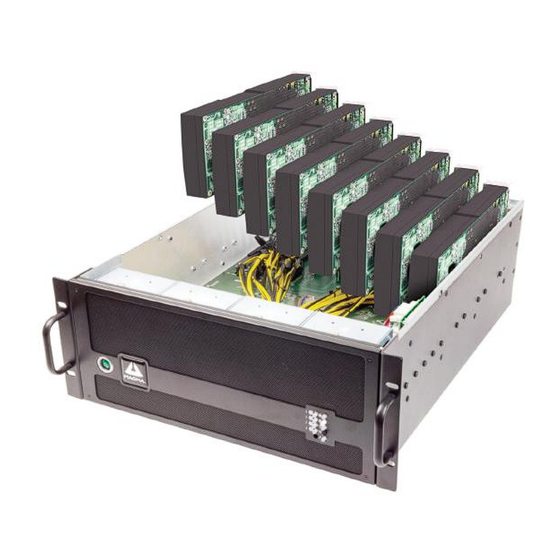
Introduction EB3600-AB Magma ExpressBox 3600-AB is a 10-Slot PCI Express® Expansion System optimized for High Performance Computing (HPC) applications. The expansion system consists of a PCIe® host interface card, High Speed/HD IO cables, a 4U rack-mount chassis containing a 10 Slot backplane and an expansion interface card, a replaceable power supply, and high CFM replaceable cooling fans. -
Page 11: Eb3600-Ab Features
2 PSUs per segment. 2400W at 120v or 3000W at 240V full power OR 1200W/1500W N+1 redundant for segment A and segment B independently. HARDWARE Backplane EB3600-AB: ten peripheral slots and two host link slots (All Gen 3 x16) Interconnect Bandwidth PCIe Gen 3 x16: 128 Gbits/sec to all peripherals and host link ENCLOSURE... -
Page 12: The Core Of Expressbox 3600
Up to two backplanes fit in 1 19” rack Mechanical cooling considerations for GPU requirements (300W Modules) PCIe Gen 3 x16 passive (invisible to system) links between all nodes including Host (Slot 0 or Slot 5) EB3600-AB | Chapter 1 Introduction... -
Page 13: Block Diagram
Magma Block Diagram Configuration Models Model 1: Configuration model for EB3600-AB, attached to one host server. Two link interface cards plugged into the server. Two link cables per interface card. EB3600-AB | Chapter 1 Introduction... - Page 14 Magma Model 2: Attached to two host servers. One Interface card per server. Two link cables per interface card. EB3600-AB | Chapter 1 Introduction...
-
Page 15: Parts List
Expansion Interface card Quick Start Guide 1200W Power Supply Modules (installed) Requires 4 Replaceable Fan (installed) For EB3600-AB, it ships with 4 power supply bricks / modules. To support 4 GPUs it requires 2 power supply bricks. EB3600-AB | Chapter 1 Introduction... -
Page 16: Components
Front Grill cover (Dust-Foam filter behind the cover) Rear Panel, you will see the following PCI Express card slot opening Interface card cable ports (x8 and x16) Power Supply RJ-45 Ethernet port Top cover Thumb Screws Power Rating Serial number EB3600-AB | Chapter 1 Introduction... - Page 17 Magma EB3600-AB | Chapter 1 Introduction...
-
Page 18: Pre-Installation Information
Gather all of the necessary tools required for installation • Read this manual • Tools Required for Installation To complete the installation of the Magma product you will need a Phillips-head screwdriver and ESD wrist strap to prevent electrostatic discharge. EB3600-AB |... -
Page 19: Chapter 2 Hardware Installation
Magma Chapter 2 Hardware Installation The following steps will guide you through the installation of your Magma Expansion System. CAUTION Hardware installation shall be performed only by qualified service personnel. Electrostatic Discharge (ESD) Warning All add-in cards are susceptible to electrostatic discharge. Use anti-static packaging when carrying or transporting cards. -
Page 20: Installation-Procedures Overview
It is highly recommended to install any 3 party PCI-E cards / High Power PCIe cards after you have verified and tested the Magma expansion is functional and no hardware failures. When installing 3 Party PCIe card, start with one card first just to see if there are any software and hardware issues or incompatibility problems that may occur. -
Page 21: Open Enclosure
By default, the 2 Expansion interface cards are already installed in their designated slot. This model EB3600-AB comes with 4 Interface cards, 2 for expansion and 2 for host server. There are two separate PCB backplanes side-by-side in the chassis. Each PCB backplane requires 1 Expansion Interface card linked to the host computer / server. - Page 22 When done verifying the SW4 and SW3 settings are correct, you can now plug in the primary Expansion Interface card in the designated PCIe “SLOT 0-UPLINK, see pictures below. EB3600-AB | Chapter 2 Hardware Installation...
- Page 23 The Interface card has a mini built-in configurable toggle switch that can be set to x4, x8 and x16. The expansion interface card default setting is x16. If the SW3 is not set correctly, your expansion system will not link up properly to the host server / computer. EB3600-AB | Chapter 2 Hardware Installation...
-
Page 24: Install Host Interface Card
PCIe slot. When the Magma interface card is used as “Host” interface i.e. installed in the host computer, the RED switch should remain OFF. Check the Dipswitch and make sure it is set to OFF=HOST. - Page 25 The host computer dictates what link width and speed the expansion system will operate in. EB3600-AB | Chapter 2 Hardware Installation...
-
Page 26: Host Card Installation In A Slot-Carrier
If you are using a server- type computer that has a slot-carrier please follow the instructions below. You have to remove the slot-carrier housing from the host server in order to install the interface card. Install Interface card EB3600-AB | Chapter 2 Hardware Installation... - Page 27 Magma Secure Interface card Put the slot-carrier housing back into the host server Install the second Host interface card in the second slot carrier EB3600-AB | Chapter 2 Hardware Installation...
-
Page 28: Connect Interface Cables
Magma Connect Interface Cables The EB3600-AB expansion unit uses High Speed / High Density IO cables (HDLSP- High Density Low Skew Pair cable) that deliver superior performance. It is an ideal solution for super-computing and data storage applications including servers, blade servers, and server clusters, providing vast modularity between systems and subsystem. - Page 29 The pictures below are example of a cable with a damaged /broken pin. When the cable is detached or not connected, please use the plastic cap to cover the end connector of the cable. This will protect the connector and prevent the pins from being damaged. EB3600-AB | Chapter 2 Hardware Installation...
-
Page 30: How To Insert The Cable Correctly
The Interface card is installed vertically as illustrated below. The image on the left side is the correct orientation of the cable, the orange plastic tab is facing toward the right side. The image on the right is the incorrect cable orientation. EB3600-AB | Chapter 2 Hardware Installation... - Page 31 / enclosure. The interface card label is upside down. This means you have to flip the cable prior to inserting to the cable port. The Image on the left is the correct position, the image on the right is the incorrect one. EB3600-AB | Chapter 2 Hardware Installation...
-
Page 32: Connect Cables To Expansion Unit
Magma Connect cables to expansion unit FOR EB3600-AB, you need four cables. Plug in cables to Magma EB3600-AB unit Connect the first set of cable to the expansion interface card located on the left side of the expansion unit. ... - Page 33 Magma See pictures below for proper installation of cable retainer (cable clamp) EB3600-AB | Chapter 2 Hardware Installation...
-
Page 34: Connect Cables To Computer / Server
Do the same thing to the remaining 3rd and 4th cables. Make sure to connect the end of the cables to the appropriate ports. Secure all the cables with a retainer clamp. This is an overview of what it looks like after connecting the cables to Magma EB3600-AB and Host Server / Computer. See picture below. EB3600-AB | Chapter 2... -
Page 35: Proper Placement Of Cables
It is important to know what correct port to use to plug in the cable. Plugging in the cable to the wrong port will render the expansion unit inoperable. Standard Cable vs. Daisy Chain Configurations EB3600-AB | Chapter 2 Hardware Installation... -
Page 36: Install Pcie Card / Gpu
GPU in the far right of the backplane (looking from the rear). This will allow you to see the slot location and align the GPU connector easily on top of the slot. Start installing the GPU one at a time from right to left. EB3600-AB | Chapter 2 Hardware Installation... - Page 37 Make sure that all cards are fully seated in their connectors. When correctly seated, there will be a firm resistance when you pull up gently the card. To keep the cards in place, secure them in the enclosure with their retaining screws. EB3600-AB | Chapter 2 Hardware Installation...
-
Page 38: Connect Auxiliary Power
GPUs have a built-in AUX power port in which you may attach the PCIe cable connector. The picture below shows how the 6+2 pin connector is attached to the GPU. EB3600-AB | Chapter 2 Hardware Installation... -
Page 39: Pcie Card Memory Requirements
All supported GPU cards require enablement of the BIOS setting that allows greater than 4 GB of memory- mapped I/O (MMIO). Standalone Server: If the server is used in standalone mode, this BIOS setting is enabled by default: Advanced > PCI Configuration > Memory Mapped I/O Above 4 GB [Enabled] EB3600-AB | Chapter 2 Hardware Installation... -
Page 40: Pcie Card Power Requirements
75 Watts 8 pin connector provides 150 Watts Magma EB3600-AB uses a 6+2 pin PCIe power connectors. It can be used as 6-pin or 8-pin connector depending on what the PCI-E card or GPU required. EB3600-AB | Chapter 2... -
Page 41: K-80 / Gpu Installation
(looking from the rear). Allowing you to see the slot location and align the GPU connector easily on top of the slot. Start installing the GPU one at a time from right to left. EB3600-AB | Chapter 2 Hardware Installation... - Page 42 Magma EB3600-AB | Chapter 2 Hardware Installation...
-
Page 43: Connect Auxiliary Power Adapter
Connect Auxiliary power adapter 1. Connect breakout auxiliary power adapter to K80 power connector. 2. Connect the EB3600-AB auxiliary power connector to the K80 breakout auxiliary power adapter. The K80 comes with a breakout auxiliary power adapter. Connect the breakout auxiliary power adapter to K80 power connector. -
Page 44: Double-Wide Gpus Vs. Single-Slot Gpus
Backplane B/2, you can only fit 4 double-wide GPUs or 5 single-slot GPUs A double-wide GPU takes up two PCIe slots. To address this issue, we enlarged the space in-between two slots on the backplane. The EB3600-AB expansion backplane can accommodate multiple double-wide GPUs. -
Page 45: Connect Power Cord / Cable
15A 220v-230v power cord / plug. Power Plug and Electrical outlets vary from country to country. Plug-in all power cords to the expansion chassis. Each supplied power supply will come with a power cord. Up to four Power Cords for EB3600-AB. A single expansion backplane has two power supply modules that require 2 power cords. -
Page 46: Use Two Separate Circuit Lines
120 volts (note that double breakers are double the current, if your household voltage is 120 then double breakers are 240 volts). In order to power up the system you would need sufficient circuits. Like other appliances, EB3600-AB expansion unit requires a set amount of volts. - Page 47 Once you have plugged in all power cables to proper electrical outlets or turned the power strip switch to ON position, all AMBER LEDs are immediately illuminated on the back of the power supply unit. Each power supply module is designated with one indicator LED (see picture below). EB3600-AB | Chapter 2 Hardware Installation...
-
Page 48: Power On The Expansion Unit
“standby mode. Power ON the expansion unit Press the power button on the front switch to power up the EB3600-AB-P unit. Turn on the expansion chassis first before powering ON the host computer. Check your installation before powering up expansion chassis for the first time. Although the power supply has an over voltage protection device built into it, it may not "trip"... -
Page 49: Power On Computer
Then power on your computer. This will enable your Magma chassis to turn ON. Hardware Check Once you have turned ON the Magma EB3600-AB and the host computer, the next thing to do is to check the LED status on the hardware. Verify that the following LEDs on the expansion card, host card, backplane, and front panel are illuminated. -
Page 50: Host & Expansion Interface Cards Leds
D4, D3, D8, and D8 Solid Green None The picture below shows the number of solid green LEDS that are illuminated on the Expansion and Host Interface cards when the unit is operating normally. EB3600-AB | Chapter 2 Hardware Installation... -
Page 51: Front Panel Status Leds
D14, D12, D10, D8, D6, D4, D2, D42 Solid Green D1, D3, D5, D7, D9, D11, D13 Solid Green D33, D39, D40, D41, D43, D44, D16 None D37, D36, D35, D33, D32, D15 None EB3600-AB | Chapter 2 Hardware Installation... -
Page 52: Completing Hardware Set Up
Your hardware set up is now complete. You should have fully integrated all the GPUs in the EB360-AB expansion unit and connected to host servers. The picture below shows what your EB3600-AB configuration looks like after completing the set up. - Page 53 Magma Top view layout of EB3600-AB attached to two servers Top view layout EB3600-AB attached to one server EB3600-AB | Completing Hardware Set up...
-
Page 54: Chapter 3 Software Installation
Chapter 3 Software Installation Install Software Skip this part; you do not need to install driver or software for the Magma EB3600-AB expansion unit. IMPORTANT Magma requires no driver for Windows, Mac OS, Linux and other Operating Systems. Verify Installation Windows No additional software or drivers are needed. -
Page 55: Linux
There are so many registers and settings associated with PCI Express Switches. For example, the image below is showing the Magma Chassis on Bus 2, Device 0, and Function 0. Some information has been deleted, but notice the Link Supported Speed is 8GT/s, Width x16 . This is helpful to know that the chassis is configured for x8 PCI Express Speeds highlighted in red In order to obtain detailed information you must login as a sudo user in Linux and type “lspci –vv”... - Page 56 Use the “lspci | grep 8796” command to check that the Magma card slot devices are detected (see image below). Below is the output text of “lspci-vv”. Showing all Magma card slot devices with two GPU cards installed. Magma devices are highlighted in red. Two GPUs plugged in are highlighted in green.
- Page 57 Capabilities: [68] Express Downstream Port (Slot+), MSI 00 Capabilities: [a4] Subsystem: PLX Technology, Inc. Device 8796 Capabilities: [100] Device Serial Number aa-87-00-10-b5-df-0e-00 Capabilities: [fb4] Advanced Error Reporting Capabilities: [138] Power Budgeting <?> Capabilities: [10c] #19 EB3600-AB | Chapter 3 Software Installation...
- Page 58 Capabilities: [40] Power Management version 3 Capabilities: [48] MSI: Enable+ Count=1/8 Maskable+ 64bit+ Capabilities: [68] Express Upstream Port, MSI 00 Capabilities: [a4] Subsystem: PLX Technology, Inc. Device 8796 Capabilities: [100] Device Serial Number aa-87-00-10-b5-df-0e-00 EB3600-AB | Chapter 3 Software Installation...
- Page 59 0b:10.0 PCI bridge: PLX Technology, Inc. Device 8796 (rev a) (prog-if 00 [Normal decode]) Flags: bus master, fast devsel, latency 0 Bus: primary=0b, secondary=0f, subordinate=0f, sec-latency=0 I/O behind bridge: 0000d000-0000dfff Memory behind bridge: f4000000-f50fffff EB3600-AB | Chapter 3 Software Installation...
- Page 60 Flags: bus master, fast devsel, latency 0, IRQ 17 Memory at f5080000 (32-bit, non-prefetchable) [size=16K] Capabilities: [60] Power Management version 3 Capabilities: [68] MSI: Enable- Count=1/1 Maskable- 64bit+ Capabilities: [78] Express Endpoint, MSI 00 Kernel driver in use: snd_hda_intel Kernel modules: snd_hda_intel EB3600-AB | Chapter 3 Software Installation...
-
Page 61: Check / Verify Pcie Cards / Gpu
In Linux operating system you can use the following commands to check if the GPUs or PCIe cards are detected or not. Use the “lspci -vtt” Use the “ lspci | grep NVIDIA”, see picture below. You can replace NVIDIA with another name of GPUs or PCIe cards. EB3600-AB |... -
Page 62: Chapter 4 General & Technical Information
Magma Chapter 4 General & Technical Information EB3600-AB Top view EB3600-AB | Chapter 4 General & Technical Information... -
Page 63: Placement Of Gpus On The Expansion Backplane
Backplane A /1 5 PCIe slots can accommodate 5 single-wide GPUS or 5 double-wide GPUs Backplane B/2 5 PCIe slot can accommodate 5 single-wide GPUS, but can only accommodate 4 double-wide EB3600-AB | Chapter 4 General & Technical Information... -
Page 64: Eb3600-Ab With 10 "Single-Wide" Gpus
Magma EB3600-AB with 10 “single-wide” GPUs EB3600-AB with 9 “double-wide” GPUs EB3600-AB | Chapter 4 General & Technical Information... -
Page 65: Proper Placement Of Gpus
Magma Proper Placement of GPUs Different placement configurations of double-wide GPUs on the backplane of the EB3600-AB are illustrated below. For example, when running 4 GPUs you must equally distribute the number of GPUs that you are installing on each backplane. It will be 2 on the first side of the backplane A and the remaining 2 on the other side of backplane B. - Page 66 Magma EB3600-AB | Chapter 4 General & Technical Information...
- Page 67 Magma EB3600-AB | Chapter 4 General & Technical Information...
- Page 68 Magma EB3600-AB | Chapter 4 General & Technical Information...
-
Page 69: Backplane Pcie Slots And Ports Assignment
Backplane PCIe slots and Ports assignment Each PCIe slot has its own port assignment, see picture below. There are 12 PCIe slots on the EB3600-AB backplane, two are occupied by the Expansion interface card and 10 slots are available. All 12 slots have their own corresponding port. -
Page 70: Backplane And Leds
3V3SL4 (D40) Debug 3V3SL5 (D41) Debug RESET (D42) PCIe Reset EB3600-AB is in reset EB3600-AB is out of reset DEBUG (D43) Debug 0V9A (D2) 900 mV Analog Power Solid - power rail OK OFF - power rail out of range 3V3 CLK (D4) 3.3V Clock Power... -
Page 71: Card Slot Link Leds
Debug 12VSL5 (D35) Debug 3V3SL0 (D36) Debug RESET (D42) PCIe Reset EB3600-AB is in reset EB3600-AB is out of reset DEBUG (D43) Debug DEBUG (D44) Debug 0V9A (D2) 900 mV Analog Power Solid - power rail OK OFF - power rail out of range 3V3 CLK (D4) 3.3V Clock Power... -
Page 72: Interface Card And Leds
If any of the Interface cables are not connected correctly, the LED D5 will stay ON (Amber). Once the cables are connected correctly and the expansion board is powered on and the host is turned on then the amber LED D5 should be off. EB3600-AB | Chapter 4 General & Technical Information... -
Page 73: Display Functions Of Interface Card Leds
For any link below gen 3, the display will alternate between these two. A 75% on 25% off duty cycle indicates a gen 2 link whereas a 25% on 75% off duty cycle is a gen 1 link. EB3600-AB | Chapter 4 General & Technical Information... -
Page 74: Reset & Power Status Leds
1.0V good When on means that the locally generate 1.0V is good and within 1.0V is bad 1.0V is specification. When off means that there is a problem with the local good 1.0V EB3600-AB | Chapter 4 General & Technical Information... -
Page 75: Front Panel Status Leds
You can only do this once the chassis is turned off, but still operates on standby power. So, ensure the power cable is connected between the chassis and the AC outlet. Fan LEDs Temperature Sensor Alarm LEDs EB3600-AB | Chapter 4 General & Technical Information... -
Page 76: Power Supply Indicator Leds
LEDs will turn orange and the device will reboot to its default settings, all LEDs should turn on solid Green. Control Switches There are four control switches on the interface card: SW1, SW2, SW3 and SW4 EB3600-AB | Chapter 4 General & Technical Information... -
Page 77: Sw1 And Sw2
Link width can be changed by using the following dipswitch settings. By default, the card is set to x16. Toggle switch for interface mode setting , the interface card can be used either host or expansion . Below are the two mode-settings for the interface card. EB3600-AB | Chapter 4 General & Technical Information... -
Page 78: Fan
GPUs. These are high CFM / RPM and replaceable fans. The picture below is the top view of the EB3600-AB unit (viewing from the back-end) showing the order of fans starting from left to right. Each fan is labeled with a number that corresponds to their fan-slot assignment on SNMP web management. -
Page 79: Fan Replacement
Fan Replacement EB3600-AB is designed to allow fan replacement while the chassis is powered on. First you will need to remove the chassis lid. Then locate the fan that has failed, unlock its thumbscrew, lift up its metal tab and pull it out. -
Page 80: Snmp / Netburner
If you need to replace your defective or non-functional NetBurner module follow the instructions below. Position the expansion unit on its side to gain access to the NetBurner module. Unplug the Ethernet cable. EB3600-AB | Chapter 4 General & Technical Information... - Page 81 Use firm upward pressure underneath the card and a gentle rocking motion until the card comes loose, see pictures below. EB3600-AB | Chapter 4 General & Technical Information...
-
Page 82: Netburner Installation
Align the Netburner module on top of the Interface board connectors. Gently apply pressure on top of the Netburner module and slowly press it down until the board is firmly seated. Reconnect the Ethernet cable to the RJ45 port. EB3600-AB | Chapter 4 General & Technical Information... -
Page 83: Replacing The Interface Board
Magma Replacing the Interface Board Disconnect all the wires including the Ethernet cable from the board, see picture below. Remove screw and nuts, see picture below. Remove the interface board. EB3600-AB | Chapter 4 General & Technical Information... -
Page 84: Netburner Interface Board Installation
To install the new Interface board, just follow the previous steps in reverse order. Place the board in the chassis and align it on top of the 4 mounting screw-holes. Secure the board. Connect all wires and plug in the Ethernet cable. EB3600-AB | Chapter 4 General & Technical Information... -
Page 85: Power Supply Unit
Configurable and replaceable power supply solutions of (1200W, 2400W, 3600W or 4800W). Magma EB3600-AB Expansion chassis uses a redundant power supply with the ability to easily replace a power module in the event of a failure. It includes two replaceable modules that share the power load requirements during normal operations. - Page 86 PSU#1 is located on the far left side of the expansion chassis and PSU#4 is on the far right side of the expansion unit. The “Input Rating” (110-240) label is located on top of the power supply module. EB3600-AB | Chapter 4 General & Technical Information...
-
Page 87: How To Add Power Module To Eb3600
Magma How to Add Power Module to EB3600 Steps on how to add two additional power supply modules to EB3600-AB unit. Power Supply Specifications Scope This document defines a series of power supply systems with the output power of up to 1200W and with +12V &... - Page 88 The remote sensing is provided to +12V, +5V, and +3.3V outputs to compensate for excessive cable drops. b) +5V, +3.3V, and -12V outputs are located on the power distribution backplane. DC Output Load Distributions The Table 3 defines the power supply typical output load distribution. EB3600-AB | Chapter 4 General & Technical Information...
- Page 89 No damage or hazardous condition will occur with all the DC output connectors disconnected from the load. The power supply may latch into the shutdown state. Isolation Primary to Secondary 4242Vdc Primary to Earth GND 2800Vdc EB3600-AB | Chapter 4 General & Technical Information...
- Page 90 Non-operating 5% to 95% relative humidity (non-condensing) Altitude Operating 0 to 16,000 feet (5000 meter) Storage 0 to 50,000 feet Mean Time between Failures (MTBF) 100K hours minimum at full load 25 EB3600-AB | Chapter 4 General & Technical Information...
-
Page 91: Chapter 5 Management Console I/O Manager
Chapter 5 Management Console I/O Manager EB3600-AB contains extra features that could be utilized to monitor the status of the components on the backplane and the items in the chassis such as the state of the power supplies, fan status, and temperature. -
Page 92: To Access Express Io Manager / Snmp
40 can really be any free number other than 10. To verify we have successfully detected the Magma Expansion chassis on our network open your web browser and direct it to the IP address of the chassis that is 192.168.1.10. -
Page 93: How To Configure Your Network Setting In Linux / Ubuntu
Type ifconfig, to check and verify that the new IP address and Subnet mask have been accepted (see screenshot below). When done, you can reset the Network Adapter IP address and restart your Network Manager. EB3600-AB | Chapter 5 Management Console I/O Manager... -
Page 94: Launch Internet Browser
If it is damaged or broken please replace it with a known good cable. Authentication Log-in The Authentication login for the browser will appear. The define username will be “default” and the password to be “magma”. Windows Log-in screen: EB3600-AB | Chapter 5 Management Console I/O Manager... -
Page 95: Default Home Webpage
Magma Linux / Ubuntu Log-in screen: Default Home Webpage The user will be directed to the MAGMA home webpage for the expansion device. See screenshot below as the default home webpage. Management Console / Web GUI HOME The HOME page provides an overview for the status of the chassis. It allows you to view the number of fans, power supplies, and temperature sensors that are attached to your chassis along with the number of users that have access to the device. -
Page 96: Administrator
In the SNMP Settings, the main administrator of the device can either activate or deactivate the monitoring system by using the check-box option. You can also obtain an MIB file in text format for a report. EB3600-AB | Chapter 5 Management Console I/O Manager... -
Page 97: Alarm Settings
Alarm Settings. These settings are recommended to stay at its default condition. NETWORK The Network tab allows you to change your IP address. It can also permit or prevent certain IP addresses from accessing the extended feature of the chassis. EB3600-AB | Chapter 5 Management Console I/O Manager... -
Page 98: Remote Management
1. Plug in the power cord to the unit 2. Do not press the front power button 3. Launch internet browser, enter 192.168.1.10, enter username and password 4. Click 'Manage" tab 5. Click 'Turn ON Chassis. EB3600-AB | Chapter 5 Management Console I/O Manager... - Page 99 LOCATOR LED will help you find that particular unit easily. There are two “Locator LEDs, one to the front and other on the back. EB3600-AB | Chapter 5 Management Console I/O Manager...
- Page 100 LED”. There two reset buttons, one on the front and the other located on the back of the unit under the RJ45 jack. You can press either the front or rear reset button. EB3600-AB | Chapter 5 Management Console I/O Manager...
-
Page 101: Pci-E Info
PCIe card or GPU will show an active status. Slots with no cards or GPUs will show “not active”. The picture below will serve as your reference guide in identifying which side of the expansion unit that corresponds to the PCIe info TAB. EB3600-AB | Chapter 5 Management Console I/O Manager... - Page 102 Magma 9 double-wide GPUs and their corresponding slots and ports assignment, see picture below. EB3600-AB | Chapter 5 Management Console I/O Manager...
- Page 103 Magma 10 single-slot GPUs and their corresponding slots and ports assignment, see picture below. EB3600-AB | Chapter 5 Management Console I/O Manager...
-
Page 104: Servicing The Side A Or Side B
3.3v standby to turn on the side A or B otherwise when you turn on your host, host turn on will not work. This is enabled by default. SIDE A= Turn A Aux Power Off SIDE B = Turn B Aux Power Off EB3600-AB | Chapter 5 Management Console I/O Manager... -
Page 105: Deactivating Server A/B (Side A/B)
Example: servicing server B / side B Power down/Shutdown the host computer Go to 192.168.1.10 using your internet browser to start Express IO Manager a. Username will be “default” and the Password will be “magma”. Click Manage Click "Turn B Aux Power OFF". -
Page 106: Reactivating Server A/B (Side A/B)
Verify it is ON, check 3.3v LED on the backplane in the expansion chassis it should be ON. Go back to Express IO Web GUI, click PCI-E Info. Check Upstream Slot B-5: 3.3V Standby is ON ( and 12V is ON). Turn On the host computer. EB3600-AB | Chapter 5 Management Console I/O Manager... -
Page 107: Fan Control
MAGMA does not support lowering the fan speed, do this at your own risk. It is not recommended to lower the fans speed to reduce noise when running high end GPUs as it can heat up (increase operating temperature) and lead to failure. -
Page 108: Fan Configuration
As you increase the RPM of a fan the noise or decibel (dBa) also increases. Decreasing the RPM also decreases the noise level. MAGMA does not support lowering the fan RPM, do this at your own risk.!!! EB3600-AB | Chapter 5... -
Page 109: Reset The Chassis To Default Parameters
You should be able to login. Check, the SNMP make sure it is set back to default configuration. Flashing the Netburner This method allows you to reload the existing program or update with a new program. Go to Chapter 8 for detailed instructions. EB3600-AB | Chapter 5 Management Console I/O Manager... -
Page 110: Configure Your Snmp Agent
Browser) we can read status information and set up specific functions otherwise not available via the Web interface. The MIB Browser (or equivalent front-end SNMP software) will display the Magma chassis MIB contents in an explorer-like, Tree interface. A snapshot from the MIB Browser by iReasoning is shown below:... - Page 111 Magma Under the MIB Tree, the Magma Chassis will have status information that can be read by expanding the respective folders. This information is also available in the Web interface mentioned previously. In addition, if we expand the sendAction folder (as shown above) we gain access to “writable” functions that essentially allow us to remote-control the chassis.
-
Page 112: Chapter 6 Functional / Benchmark Tests
Fan Details, should show RPM values per each fan. FAN 1-8057 RPM (example only) FAN 2 -8192 RPM (example only) iii. FAN 3 – 8192 RPM (example only) FAN 4 – 8333 RPM (example only) EB3600-AB | Chapter 6 Functional / Benchmark Tests... -
Page 113: Replaceable Fan Test
Press the Alarm Reset Button, this should silence the alarm. b. Power Supply LED turns to solid Green. PSU Details (via Express Io Manager) should show “Power Supply is Good” d. Front Panel Status LED turn to solid Green. EB3600-AB | Chapter 6 Functional / Benchmark Tests... -
Page 114: Express Io Manager "Radio Button" Test
D. Close the Internet Browser a. Re-launch Internet Browser b. Type 192.168.1.10 Log in using the “test” account i. User name: test ii. Password: test d. You should be able to log in. EB3600-AB | Chapter 6 Functional / Benchmark Tests... -
Page 115: Chapter 7 Rack Slide Installation
Two different rack slide kits are available, 26” and 28” Rack slide kits. Each rack slide kit comes with two 7.25” adjustable mounting bracket extensions for use with the rack slides. Slide Rail Dimension Information EB3600-AB | Chapter 7 Rack Slide Installation... -
Page 116: Specifications
80 lbs Standard hardware packages include all hardware necessary to mount your Chassis: Rear mounting brackets Bar nuts (CA8056-06-0017) #10-32 x 0.50 F.H.M.S. (flush front rail mounting) #10-32 x 0.38 B.H.M.S. #10-32KEPS® nuts EB3600-AB | Chapter 7 Rack Slide Installation... -
Page 117: Safety Instructions
Magma Safety Instructions Always use caution when servicing any electrical component. Before handling the Magma Expansion chassis, read the following instructions and safety guidelines to prevent damage to the product and to ensure your own personal safety. Materials handling To reduce the risk of personal injury or damage to the equipment: Practice local occupational health and safety requirements and guidelines for handling materials. -
Page 118: Tools And Supplies Needed
Phillips* (cross head) screwdriver (#1 bit and #2 bit) Measuring Tape Parts List Item# Description Slide Rails Bags of Assorted Nuts & Bolts, Bar Shim and 2 Short End Brackets End Brackets (2-long) EB3600-AB | Chapter 7 Rack Slide Installation... - Page 119 The rack slide is composed of three parts, see picture below. Item A, is mounted on the side of the chassis. Items B and C are mounted to the rack cabinet. Item D, is the end bracket. This is attached to the very end of the SLIDE item B. EB3600-AB | Chapter 7 Rack Slide Installation...
-
Page 120: Slide Rail Installation Instructions
You will be mounting this part of the expansion chassis. The remaining assembly includes slide piece C inside slide piece B. Prepare the end bracket extension. The end bracket D will be added to slide piece B in Step 3. EB3600-AB | Chapter 7 Rack Slide Installation... -
Page 121: Attach Rail To Chassis (Step 2)
Assemble Slide Rails (STEP 3) Measure the rack from front to back so you can confirm how long the rail must be to fit properly. In this example, the rack is 29” long. EB3600-AB | Chapter 7 Rack Slide Installation... - Page 122 Ensure the Phillips screw head is located on the “open” side of the Slide pieces as shown below. Tighten finger tight only to allow for minor adjustment during assembly in the Step 5. EB3600-AB | Chapter 7 Rack Slide Installation...
-
Page 123: Add Screws To Rack Post (Step 4)
Attach Slide Rail to Rack (STEP 5) Attach to inside of rack with “fingers” pointing “out” and the end bracket to the rear. Secure each Slide Mount with 4 screws as shown below. EB3600-AB | Chapter 7 Rack Slide Installation... - Page 124 Magma EB3600-AB | Chapter 7 Rack Slide Installation...
-
Page 125: Attach Chassis To Slide Rail / Rack (Step 6)
Next, press on the safety Latch on slide piece A and continue to push until it stops again. Press on the safety catch again to allow the chassis to slide all the way into the rack. EB3600-AB | Chapter 7 Rack Slide Installation... -
Page 126: Secure The Chassis To The Rack (Step 7)
Use 2 Panhead screws, on each side, to secure the chassis to the rack as shown below. Earth Leakage Current To reduce the risk of electric shock due to high leakage currents, ensure that there is a reliable grounded (earthed) connection before connecting power distribution products to AC power. EB3600-AB | Chapter 7 Rack Slide Installation... -
Page 127: Grounding The Eb3600-Ab Expansion Chassis
Magma Grounding the EB3600-AB Expansion Chassis CAUTION The system chassis must be securely grounded to the rack cabinet frame. Do not attempt to connect power to the system until grounding cables are connected. Completed power and safety ground wiring must be inspected by a qualified electrical inspector. An energy hazard will exist if the safety ground cable is omitted or disconnected. - Page 128 (like IEC 60320-1 connector), or both. PLUGGABLE EQUIPMENT TYPE B Equipment that is intended for connection to a MAINS SUPPLY via an industrial plug and socket-outlet or an appliance coupler, or both, complying with IEC 60309 or with a comparable national standard EB3600-AB |...
-
Page 129: Chapter 8 Updating Netburner / Snmp
Connect the Ethernet cable to RJ-45 port of Magma expansion unit and Laptop computer . Set your network connection so that you are able to ping the Express IO Manager. The Magma SNMP / NetBurner has an IP address set to 192.168.1.10 Verify your connection by pinging the IP address 192.168.1.10. -
Page 130: Launch The Autoupdate.jar
Launch the AutoUpdate.jar software tool by typing java –jar AutoUpdate.jar command in the terminal. On Device IP, type or enter 192.168.1.10. Click Browse, locate the “EB3450_x_x_x.APP.s19” file, and then click “Open”. See screenshot below as example. EB3600-AB | Chapter 8 Updating Netburner / SNMP... - Page 131 Magma Check Reboot. Click Update and the “Authentication login screen” will come up. Login as “default” for UserName, magma for Password. Click OK and it will commence loading the program. When done, it will show “100 Percent complete” and “Programming completed without Error”.
-
Page 132: Check And Verify The Update
Authentication login comes up. Enter “default” for User Name and magma for Password. The user will be directed to the MAGMA Express IO Manager default home webpage. The screenshot below shows where to find the version of Express I/O Manager. -
Page 133: Chapter 9 Troubleshooting
Troubleshooting Locate the Problem If you are having trouble with the Magma Expansion chassis, first verify that all cards and cables are seated properly. Be sure you followed the instructions in earlier sections of this manual. Always remember to power On and Off correctly when rechecking your installation. - Page 134 If the expansion chassis is not visible in your Windows Device Manager, you will need to turn off your computer (first) and then the Magma Expansion chassis (second) and test all cords and cables to ensure you have everything connected correctly. If everything seems to be connected correctly, and you are...
-
Page 135: Chapter 10 Chassis Maintenance
General Chassis Cleaning The environment where your Magma chassis is operating should be the determining factor as to how often you should perform a general cleanup of the chassis. To perform a routine general cleaning of your chassis, you will need the following: 1. -
Page 136: Cleaning The Air Filter
The chassis is equipped with an air filter that is easy to remove and clean. To keep your chassis running at its coolest, you should clean this filter regularly. How often the filter requires cleaning depends on environmental conditions where your Magma Expansion chassis is located. To clean this filter, follow these simple steps. -
Page 137: Chapter 11 Frequently Asked Questions (Faq)
12. Can I use iPass cable? Answer: The EB3600-AB x16 host card is Gen3 and it has different cable ports and will NOT accept i-Pass cable. The x16Gen2 host card can be used with the EB3600-AB expansion chassis but performance will train down to Gen2. - Page 138 19. Can I plug in a GPU or any PCIe cards while the EB3600-AB is On? Answer: Do not plug any PCIe cards while the EB3600-AB is on as this can cause electrical short and damage on the PCIe card and PCIe slot.
-
Page 139: What Are The Differences Between Eb3600-10 And Eb3600-Ab
Magma What are the differences between EB3600-10 and EB3600-AB? Answer: See info / table below. EB3600-10 EB3600-AB Features / Functions Shared Power Supply subsystem for all Separate power supply subsystems for ‘A’ and ‘B’ slots, up to 4 PSUs with a total of 4800W segment of system. -
Page 140: Chapter 12 How To Get More Help
If factory service is required, a Service Representative will give you a Return Merchandise Authorization (RMA) number. Put this number and your return address on the shipping label when you return the item(s) for service. Magma will return any product that is not accompanied by an RMA number. Please note that Magma WILL NOT accept COD packages, so be sure to return the product freight and duties-paid. -
Page 141: Online Support Resources
Online Support Resources As a Magma product user and customer, listed below are our Online Support Resources Magma has a video tutorial in which you may find very useful. We encourage that you all subscribe to it. Here are the links: ... -
Page 142: Appendix A Compliance
Cetappareilnumériqué de la classe A estconformé à la norme NMB-003 du Canada The product(s) described in this manual complies with all applicable European Union (CE) directives. Magma will not retest or recertify systems or components that have been reconfigured by customers EB3600-AB | Chapter 12... - Page 143 Manual Part Number: 09-09957-02 REV C...
Need help?
Do you have a question about the EB3600-AB and is the answer not in the manual?
Questions and answers