
Summary of Contents for Eurotherm 7100A
-
Page 1: User Manual
7100A User Manual Single Phase Power Thyristor Units Issue 4.4 HA176499ENG March 2011... - Page 2 © Copyright Eurotherm Automation 2002 All rights reserved. All reproduction or transmission in any form whatsoever and using any procedure (electronic or mechanical, including photocopying and recording) without written permission from Eurotherm is strictly prohibited. Ref.: HA176499 ENG - Issue 4.4 - 2011/03...
- Page 3 ......... .7-1 PURPOSE OF MANUAL This is the Issue 4.4 User Manual. It describes the Basic Version and all options for 7100A series power thyristor units with current ratings from 16A to 250A. 7100A User Manual...
- Page 4 - AC semiconductor controllers and contactors for non-motor loads’. CE LABELLING 7100A products installed and used in accordance with the user manual, bear CE labelling on the basis of compliance with the essential requirements of the European Low Voltage Directive 73/23 EEC...
- Page 5 ICO calibrations and threshold Chapter 4,, I lim potentiometer while firing at full rate Page 5-7 Optimise firing delay DLY potentiometer Page 3-3 for inductive load Adjust DLF alarm Page 5-5, 5-6 CHK/SET push button (if conditions met) 7100A User Manual...
-
Page 6: Table Of Contents
1.3. Coding ........... .1-11 7100A User Manual... -
Page 7: General Presentation
Chapter 1 IDENTIFICATION 1.1. GENERAL PRESENTATION 7100A series power thyristor units are used to control the electrical power of single phase industrial loads of all types. The load controlled may may be : high or low temperature coefficient resistive loads, short wave infrared elements or transformer primaries. - Page 8 (Burst mode or single cycle) Control terminal references Auxiliary supply terminal references Control (if specified) terminal block Auxiliary supply terminal block (if specified) Power terminals (load side) Figure 1-1 General view of 7100A power thyristor unit 16A to 40A ‘lite’ version 7100A User Manual...
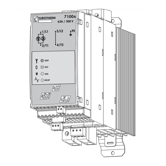
- Page 9 Identification 1.1.2. 7100A units from 16A to 63A ‘full’ version and 63 A ‘lite’ version Figure 1-2 General view of 7100A power thyristor unit 16A to 63A ‘full’ version and 63 A ‘lite’ version 7100A User Manual...
- Page 10 Diagnostic alarm Electronics push button power supply Firing request VICL option: (Phase Angle) Power calibration Control terminal references Control connectors Power terminals (load side) Figure 1-3 General view of 7100A power thyristor unit 80A to 100A ‘full’ version 7100A User Manual...
- Page 11 Over Temperature Alarm (250 A only) Control Terminals Fan Power Supply (250 A only) Power Terminal used (Load Side) (250 A only) Figure 1-4 General view of 7100A power thyristor unit 125A to 250A ‘lite’ version only 7100A User Manual...
-
Page 12: Technical Specifications
80 to 100 125 to 250 Note (1) : Basic product, without alarm option or control (except V2 and OL) Note (2) : Product with one control option (I2 or V2CL) or one alarm option (GRF or DLF) 7100A User Manual... -
Page 13: Control
• Delay on first firing set by potentiometer on front panel. For all loads in Phase Angle firing: Safety ramp with each change of setpoint. 1.2.7. Signalling Electronics supply present: green ‘ON’ LED. Thyristor firing request: green ‘HEAT’ LED. 7100A User Manual... -
Page 14: Alarms
The relay contact (0.25 A/230 Vac; 32 Vdc) is either open on alarm or closed on alarm depending on the product code. Eurotherm’s policy of continuous product improvement and development means that the specifications in this document may be modified without prior notice. -
Page 15: Protection
Degree 2 acceptable (defined by IEC 60664). Humidity RH 5% to 95%, non-condensing, non-streaming. Over-voltage Over-voltage category II (as defined by IEC 60664) U = 4kV Isolation voltage Assigned voltage of isolation U = 500 Veff 1-10 7100A User Manual... -
Page 16: Coding
250A: - 115 V fan and 115 V 115V - 230 V fan and 230 V 230V 5. Thyristor fuse Code Fuse without fuse blown microswitch FUSE Fuse with fuse blown microswitch MSFU No fuse NONE 1-11 7100A User Manual... - Page 17 (with DLF option and burst firing) Overload alarm except codes SWIR, XFMR, VICL and V2CL No over-current alarm XXXX 16. Alarm relay contact Code With alarm option: Contact closed on alarm Contact open on alarm Without alarm option 1-12 7100A User Manual...
-
Page 18: Chapter 2 Installation
... .2-12 2.3.2.7. MSFU option, fuse blown contact .....2-12 7100A User Manual... -
Page 19: Safety During Installation
2.1. SAFETY DURING INSTALLATION (MOUNTING AND WIRING) Danger! • 7100A power thyristor units must be installed and wired by qualified staff authorised to work on low voltage industrial electrical facilities. • Units must be installed in a fan-cooled cabinet, to ensure that condensation and pollution are excluded, with a class of at least 2 according to IEC 664. -
Page 20: Types Of Mounting
Table 2-1 Attachment details for both mounting types 2.2.1. ATTACHMENT PLATE The attachment plate, shipped fitted to the rear of the 7100A power thyristor unit, is used: • to clip the unit to a DIN rail, or • to screw the unit to a bulkhead. -
Page 21: To 63A Units Mounting
EN50022 DIN rail Mobile attachment hooks Catch to move mobile hooks downwards Figure 2-1 Attaching the 7100A power thyristor unit to a DIN rail (16A to 63A, rear view) 2.2.3.2. BULKHEAD MOUNTING For M4 screw Attachment plate For M4 screw... -
Page 22: To 100A Units Mounting
Mobile attachment hooks Catch to move mobile hooks downwards Lower attachment plate Figure 2-3 Attaching the 7100A power thyristor unit to DIN rails (80A and 100A, rear view). 2.2.4.2. BULKHEAD MOUNTING For 2 M4 screws Upper attachment plate Lower attachment... -
Page 23: 125A To 250A Units Mounting
Installation 2.2.5. 125A TO 250A UNITS MOUNTING BULKHEAD MOUNTING For2 M6 screws For2 M6 screws Figure 2-5 125A to 250A 7100 A unit mounting 7100A User Manual... -
Page 24: Wiring
2.3. WIRING 2.3.1. POWER CONNECTIONS 7100A power thyristor units with current ratings up to 100 A are fitted with: • one channel controlled by thyristors • an internal busbar for directly connecting the load to the power supply (direct channel, not controlled by thyristors). -
Page 25: 7100A Units From 16A To 100A Wiring Diagram
Installation 2.3.1.1. 7100A units from 16A to 100A wiring diagram The power connection to 7100A units is between one phase and neutral or between two phases depending on the nominal voltage for the thyristor unit. N / Ph2 Supply protection and... -
Page 26: 7100A Units From 125A To 250A Wiring Diagram
Installation 2.3.1.2. 7100A units from 125A to 250A wiring diagram The power connection to 7100A units is between one phase and neutral or between two phases depending on the nominal voltage for the thyristor unit. Protective Earth terminal L2 / N Supply protection and cut-out. -
Page 27: Control Connections
Installation 2.3.2. CONTROL CONNECTIONS Terminal blocks on the underside of the 7100A power thyristor unit are used to connect: • the control signals (analogue and logic) • the auxiliary or electronics supply • alarm relay and acknowledgement contacts Examples of connecting the input signals, external electronics supply and alarm and acknowledgement contacts are shown below. -
Page 28: Control Signal
Internal +5 V (analogue signals) + Analogue control signal Figure 2-8 Control signal connection (self-powered unit without alarms) a) external signal, e.g. from Eurotherm series 2000 controller b) manual command from external potentiometer. 2.3.2.3. Power supply for electronics and fan (option) - A/F Terminal The power supply for the electronics (auxiliary supply) may be either •... -
Page 29: Alarm Relay Contact
2.3.2.7. MSFU option, fuse blown contact - MSF Terminal For any units from 125 A to 250 A, with the option MSFU a ontact is avalaible on the terminal MSF in order to indicate fuse blown. 2-12 7100A User Manual... -
Page 30: Chapter 3 Firing Modes
3.6.1. Ramp on start-up ........3-6 3.6.2. Magnetisation ramp (XFMR option) ......3-6 7100A User Manual... -
Page 31: General And Firing Mode Signalling
(or 50% of the power supplied to the load): The Base Cycle time is equal to 16 cycles for code C16 and 64 cycles for code C64. Figure 3-1 Thyristor firing for one of the phases, in ‘Burst mode’ 7100A User Manual... -
Page 32: Firing Delay (Xfmr Option)
The factory setting for the first firing delay with the XMFR option is 70° (typical value suitable for starting most applications). ϕ ϕ The optimum firing angle can be adjusted with the ‘DLY’ potentiometer to match the of the load to obtain a minimal transient over-current (using an oscilloscope). 7100A User Manual... -
Page 33: Single-Cycle (Code Fc1)
• Advanced single-cycle • Standard single-cycle = 0.5 cycles: T reduced) or T = 1 cycle) 66.6% power 66.6% power (F= 2 T = 2 T Figure 3-4 Exemple of Single-cycle and Advanced sigle-cycle firing mode 7100A User Manual... -
Page 34: Phase Angle (Code Pa)
Load voltage voltage voltage Current Current θ ω t ω t θ θ π π Resistive load b) Inductive load Figure 3-5 Voltage and current in ‘Phase angle’ mode a) - resistive load; b) - inductive load. 7100A User Manual... -
Page 35: Safety Ramp
XFMR option, after this ramp, the first ‘burst mode’ firing cycle starts with the first firing delay. Supply Voltage Load Voltage Load Voltage Magnetisation gradiant Delay for first firing Figure 3-7 Transformer primary power-up in ‘Burst mode’ (XFMR option) 7100A User Manual... - Page 36 4.2.3. Current and power limitation ......4-5 4.3. Current and power specifications (options) ..... . .4-5 7100A User Manual...
-
Page 37: Chapter 4 Control And Limits
4. Chapter 4 CONTROL AND LIMITS 4.1. CONTROL 4.1.1. Control parameters 7100A power thyristor units use one of the following control parameters: • rms load voltage squared V • rms load current squared I • power delivered to load P •... - Page 38 4. Rotate the potentiometer in the direction of the arrow by approx. 2 turns and acknowledge the alarm (settings-calibration for the nominal load current used). Important: If spurious alarms occur rotate the ‘I lim’ potentiometer in the direction of the arrow, one turn at a time, until the alarms cease. 7100A User Manual...
- Page 39 2. Use the ‘I lim’ potentiometer to set the I value. 3. Use the ‘VI lim’ potentiometer to set the P value. Check the resulting power setting on the HRC signal (accounting for I Important: The current limitation must be done before adjusting the power limitation. 7100A User Manual...
- Page 40 Control / Limits 4.3. CURRENT AND POWER LIMIT SPECIFICATIONS The table below summarises the operation of the limits used in the 7100A series power thyristor units. Firing Control Potentiometer Operation mode type Name Action of limit V2CL I lim Thyristor unit Current limit by threshold.
- Page 41 Control / Limits 7100A User Manual...
-
Page 42: Chapter 5 Alarms
5.7.2. Alarm conditions ........5-7 5.7.3. Alarm Actions, Memorisation, Acknowledgement ..5-7 7100A User Manual... -
Page 43: Alarm Diagnostic Summary
Partial DIAGNOSTIC: alarm: current. temperature. short-circuit short-circuit load load Phase angle Firing Firing failure failure inhibited inhibited Total zero (see page 5-7) load failure crossing Figure 5-1 Diagnosing operation and alarms according to front panel LED status 7100A User Manual... -
Page 44: Safety Mechanisms
Chapter 5 ALARMS (Options) 5.1. SAFETY MECHANISMS The alarms on the 7100A protect the thyristors and the load against certain types of abnormal operation and provide the user with information about the type of fault. • Alarms are not under any circumstances a replacement for personnel protection. -
Page 45: Load Monitoring
• Thermal faults are signalled by the ‘T°’ LED if one of the alarm options or one of the control options (except V2 and OL) is fitted. The unit is protected against thermal faults whether or not they are signalled.Thermal faults are signalled by the alarm relay if one of the alarm options is fitted. 7100A User Manual... -
Page 46: Setting The Dlf Alarm
‘CHK / SET’ (Check / Setting) push button. If the fault persists, DLF signalling returns to the alarm position. If the ICO option is used, PLF and TLF faults can be excluded from alarms using the external acknowledgement logic input (see ‘Type 2 alarm’). 7100A User Manual... -
Page 47: Functions Of Dlf Alarm Push Button
Diagnostic disabled PLF fault Alarm relay: Alarm on Alarm off Alarm on Figure 5-3b PLF monitoring diagnosis 5.6.3. Disabling Press until DLF LED stops flashing Push button > 8 s Diagnostic disabled Figure 5-3c Disabling PLF monitoring 7100A User Manual... -
Page 48: Over Load Alarm
The Over-current alarm may be acknowledged by applying +5 V to the ‘ACK’ terminal on the ‘DIG.IN’ terminal block (logic signal inputs). The internal supply (‘5VD’ terminal) or an external source may be used to acknowledge the alarm remotely (see figure 2-12). 7100A User Manual... - Page 49 Alarms 7100A User Manual...
-
Page 50: Chapter 6 Maintenance
6.3. Thyristor protection fuses ..........6-3 7100A User Manual... -
Page 51: Safety During Maintenance
Important! • Eurotherm shall not be held responsible for any damage, injury, losses or expenses caused by inappropriate use of the product or failure to comply with this manual. • Accordingly the user is responsible for checking, before commissioning the unit, that all the nominal characteristics correspond to the conditions under which it is to be installed and used. - Page 52 Maintenance 6.3. Thyristor protection fuses The thyristors in the 7100A power thyristor unit are protected against excess currents by a high-speed fuse (for all load types other than short wave infrared elements). For current ratings ≤ 100 A the fuse is external.
- Page 53 Table 6-2 Fuses with microswitch, recommended for ratings 16A to 250A (code MSFU) Important! For all loads (other than short wave infrared elements), using a thyristor protection fuse other than the recommended fuse voids the product guarantee. 7100A User Manual...
- Page 54 Processes and Power. From requirement assessment, through to equipment specification and plant commissioning. Eurotherm Limited is able to offer expertise and equipment in the following areas: • Input conditioning • Process and Temperature Indicators •...
- Page 55 © Copyright Eurotherm Automation 2002 All rights reserved. All reproduction or transmission in any form whatsoever and using any procedure (electronic or mechanical, including photocopying and recording) without written permission from Eurotherm is strictly prohibited. Represented by: HA176499ENG issue 4.4...
Need help?
Do you have a question about the 7100A and is the answer not in the manual?
Questions and answers