Table of Contents
Advertisement
Advertisement
Table of Contents

Summary of Contents for Holybro KOPIS 1
- Page 1 User Manual & Setup Guide v1.1...
-
Page 2: Table Of Contents
Using The OSD ..........................31 Saving Your Configuration ..................... 33 Pre-Flight Check ......................... 35 Best Practices For FPV ......................36 Quadcopter Safety ........................37 Adjust PIDs / Rates / vTX from Taranis ................40 P a g e KOPIS 1... -
Page 3: Overview
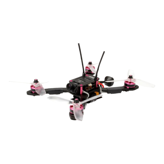
[Type here] Overview KOPIS is a high-performance ready-to-fly FPV racing drone from Holybro, Low-deck design means centralized mass and excellent handling. Stretched-X motor layout is the choice of top racers because the rear props are further from the "dirty air" coming from the front props. The result is smoother cornering and higher top speed. -
Page 4: Warranty And Return Policy
The refund amount is limited to the price of the product. Shipping costs are never refundable. Contact us at: • Email: productservice@holybro.com • Facebook Page: Holybro • Facebook Group: Holybro Shuriken Owner Group P a g e KOPIS 1... -
Page 5: Spare Parts
[Type here] [Type here] Spare Parts P a g e KOPIS 1... -
Page 6: Install Betaflight
3. 2. Run the VCP installer and let it finish. 3. Download the ImpulseRC Driver Fixer from here. 4. Run the ImpulseRC Driver Fixer. It will instruct you to plug in your flight controller. P a g e KOPIS 1... - Page 7 Also, every time you get a new flight controller, you must run the ImpulseRC Driver Fixer one time for that board, before you can flash the board. P a g e KOPIS 1...
- Page 8 To save time in the future, you can right-click the app icon in Chrome and choose “Create Shortcuts”. This will create shortcuts in your start menu and on your desktop, to launch the app directly. P a g e KOPIS 1...
-
Page 9: Install The Receiver
Stick the receiver to the top of the Atlatl video transmitter, on top of the stack. If you have used a low-profile receiver, there should be enough room between the top plate and the Atlatl. P a g e KOPIS 1... -
Page 10: Bind The Receiver
8. Power the FS-i6 transmitter back up, this time without holding down the BIND KEY. The LED on the receiver will go solid red (no blinking). This indicates that the receiver is communicating with the transmitter. P a g e KOPIS 1... - Page 11 9. Binding will be indicated by the green LED lighting up solid and the red LED blinking. If binding is not successful, most likely you didn’t fully depress the bind button. In this case, un-plug the LiPo and repeat steps 6-8. P a g e KOPIS 1...
- Page 12 LM0027 and install the Satellite receiver in your KOPIS. We suggest keeping the LM0027 around for binding of future satellite receivers. You could even buy a cheap PDB and solder the LM0027 to its 5v output pads and use that as your “binding adapter”. P a g e | 10 KOPIS 1...
-
Page 13: Verify Channel Mapping
2. We want to acknowledge all you Mode 1 flyers too. Please understand that we’re just trying not to confuse beginners with too much information. If you’re a beginner and this paragraph didn’t make sense, don’t worry about it. P a g e | 11 KOPIS 1... -
Page 14: Verify Channel Directions
6. Press Ok to cycle through the channels. Press Up or Down to choose whether the channel direction is Normal or Reversed. Reverse the required channels so that the channels move as described above in the Betaflight Receiver Tab. P a g e | 12 KOPIS 1... - Page 15 Click the jog-wheel to reverse the channel. The final configuration for most Spektrum radios is shown below. You still need to verify for yourself that the channels move the correct direction by checking the behavior in the Betaflight Receiver Tab. P a g e | 13 KOPIS 1...
- Page 16 3. Scroll to move across the line until you highlight the Direction arrow as shown above on the Roll axis. 4. Press ENTER to invert the channel direction. 5. Press EXIT to back out of the menu. P a g e | 14 KOPIS 1...
-
Page 17: Adjust Channel Centers
5. Press the Down key to move the selection arrow to “Subtrim”. Press Ok. 6. Center the transmitter sticks. The spring-loaded sticks will auto-center. You will need to manually center the left stick (throttle). P a g e | 15 KOPIS 1... - Page 18 With the transmitter sticks centered, adjust the subtrim for channels 1, 2, 3, and 4 so that the channel reads as close to 1500 as you can get it in the Betaflight Receiver Tab. P a g e | 16 KOPIS 1...
- Page 19 Click the jog-wheel to select the value. 4. Leave the sticks centered. While watching the channel in the Receiver tab, scroll the jog-wheel until the Receiver Tab shows 1500 for the channel. P a g e | 17 KOPIS 1...
- Page 20 5. Press ENTER to select the channel subtrim value. Leave the sticks centered. While watching the channel in the Receiver tab, scroll up or down until the Receiver Tab shows 1500 for the channel. 4. Press EXIT to back out of the menu. P a g e | 18 KOPIS 1...
-
Page 21: Adjust Channel Endpoints
3. Press the Down button to highlight the Functions Setup option. 4. Press Ok to enter the FUNCTIONS menu. 5. Press the Down key to move the selection arrow to “End Points”. Press Ok. P a g e | 19 KOPIS 1... - Page 22 Then use the up/down buttons on the FlySky FS-i6 to adjust the endpoint % until the Betaflight Configurator Receiver Tab shows 1000 (for the bottom endpoint) or 2000 (for the top endpoint). P a g e | 20 KOPIS 1...
- Page 23 Receiver Tab to show 1000 as its value. Hold the stick to the upper extreme of its movement (up or right) and adjust the channel endpoint to cause the Receiver Tab to show 2000 as its value. P a g e | 21 KOPIS 1...
- Page 24 Receiver Tab shows 2000 for the channel. 8. Repeat the above steps to adjust the endpoints for all four channels: Throttle, Pitch, Roll, and Yaw. 9. Press EXIT to back out of the menu. P a g e | 22 KOPIS 1...
-
Page 25: Set Up Arming Switch
We suggest using switch SF, the large two-position switch on the upper- left shoulder of the Taranis. 7. Press EXIT to back out to the main menu. Switch SF is now mapped to channel 5, Aux1. P a g e | 23 KOPIS 1... - Page 26 Good news! Our FS-i6 radio came pre-configured with the channel 5, Aux-1, pre-assigned to the upper- left switch, switch SWA. This is exactly how we want things configured for switch arming, so the FlySky is ready to go! P a g e | 24 KOPIS 1...
- Page 27 3. Turn on your transmitter. Plug in a LiPo. The small yellow indicator will move to indicate the current position of the Aux1 channel. P a g e | 25 KOPIS 1...
- Page 28 5. With the switch in the “armed” position, drag the yellow range marker to the end of the channel where the yellow indicator is. 6. Click “Save” in the lower-right of the window. YOUR MOTORS WILL NOW START SPINNING I SURE HOPE YOU REMOVED YOUR PROPS! P a g e | 26 KOPIS 1...
-
Page 29: Mount The Antenna(S)
Once everything is routed how you like, shrink the heat shrink to secure the antenna in place. Finally, cut off the excess end of the zip-tie, but be careful not to cut the actual antenna wire. P a g e | 27 KOPIS 1... -
Page 30: Customize The Osd
If your batteries are consistently resting at below this level at the end of a day of flying, then you might be shortening their lifespan at least a little. P a g e | 28 KOPIS 1... - Page 31 The mAh put back in by the battery will seldom perfectly match the mAh reported by the OSD, but by taking several measurements and averaging the results, you can usually get it reasonably close. P a g e | 29 KOPIS 1...
-
Page 32: Install The Props
Notice that the high edge of the prop blade faces the center-line of the quad on the front and back of the quad. This is the simplest way to remember how to install the props correctly. High Edge Faces Centerline P a g e | 30 KOPIS 1... -
Page 33: Using The Osd
(like battery voltage, mAh, and so forth) around on the screen. The “Alarms” sub-menu lets you control when the OSD will try to alert you that battery voltage is too low or mAh consumed is too high. P a g e | 31 KOPIS 1... - Page 34 The screen to the right shows the current vTX settings. From here, you can change the frequency band, channel, and power level of the video transmitter. After making the changes, move the cursor to “Set” and press roll-right to confirm the settings. P a g e | 32 KOPIS 1...
-
Page 35: Saving Your Configuration
9. Press the Enter key on your keyboard. The pasted-in text will rapidly scroll past. 10. Type “save” in the text box at the bottom of the screen. 11. Press Enter. The flight controller will reboot and the configuration will be restored. P a g e | 33 KOPIS 1... - Page 36 [Type here] [Type here] How To Save and Restore Your Configuration https://www.youtube.com/watch?v=HsxTqp76Brs P a g e | 34 KOPIS 1...
-
Page 37: Pre-Flight Check
Fly low to the ground and close-in. Be prepared to disarm immediately if you lose video or lose control of the quad for any reason. P a g e | 35 KOPIS 1... -
Page 38: Best Practices For Fpv
Transmitting at higher output powers increases the likelihood of interference. 25 mW is more than enough power for good range most of the time. Above 200 mW, the likelihood of interference significantly increases. P a g e | 36 KOPIS 1... -
Page 39: Quadcopter Safety
If you watch old-timers who have been doing this forever, you may even see them carry their transmitters with their finger resting on the arm switch, holding it in the disarmed position. This is a great habit to develop. P a g e | 37 KOPIS 1... - Page 40 Always plug the battery in just before setting the quad down. And for goodness sake, if your quad is doing something weird, don’t “test-fly” it in your living room. Your ceiling will thank you. P a g e | 38 KOPIS 1...
- Page 41 If you have a Taranis with an X-series receiver (bound in D16 mode), you can ensure failsafe is set correctly by choosing “No Pulses” as your failsafe mode in the Model Setup screen. If you have a Taranis with a D-series receiver (D8 mode) this setting has no effect! P a g e | 39 KOPIS 1...
-
Page 42: Adjust Pids / Rates / Vtx From Taranis
Detailed instructions for how to do this are beyond the scope of this document. Here’s a video showing how to do it. How to Adjust PIDs, Rates, and vTX Settings via Lua Script https://goo.gl/2yRWTZ P a g e | 40 KOPIS 1...
Need help?
Do you have a question about the KOPIS 1 and is the answer not in the manual?
Questions and answers