
Summary of Contents for Hover-Davis PL1200
- Page 1 PL1200 Thermal Transfer PL1200 Thermal Transfer Printer Product Guide Printer Product Guide © 2002 Hover-Davis. All rights reserved. Revision 1 6 Aug 02 No. PL1200D-E01 www.hoverdavis.com www.hoverdavis.com...
-
Page 2: Customer Support Center
Hover-Davis, Inc. has checked the contents of this printed document to verify that it is in agreement with the product described inside. However, discrepancies can and do occur. Therefore Hover-Davis, Inc. cannot assume responsibility for complete agreement between this printed document and the product described inside. -
Page 3: Table Of Contents
3.1 Installing the PL1200 Docking Station ..............23 3.2 PL1200 Software ....................23 Chapter 4: Operations ..................25 4.1 Docking and Removing the PL1200 Labeling Unit ............. 25 4.2 About Changing Media Reels ................... 26 4.3 Installing the Label Media Reels ................29 4.4 Removing the Label Media Reels ................ - Page 4 6.3 Labels Won’t Calibrate ................... 38 6.4 Testing Stock Reel Low Sensors ................40 6.5 Communication Problems ..................40 6.6 No Power to the PL1200 when Docked ..............40 Chapter 7: Schematics and Wiring ..............41 Chapter 8: Spares, Parts and Decommissioning ..........45 8.1 Recommended Spares Kit ..................
-
Page 5: How To Use This Guide
How to Use This Guide How to Use This Guide This guide is designed to help you install, operate and maintain your PL1200 labeling system. Each chapter begins with a brief overview followed by a complete discussion of each topic. - Page 6 This chapter contains the schematic and wiring diagrams for the PL1200 labeling system. Chapter 8: Spare Parts, Decommissioning, and Product Specifications This chapter contains a parts list, information on decommissioning the PL1200 labeling unit, and the product specifications for the PL1200 labeling system.
-
Page 7: Chapter 1: Safety
Safety... -
Page 8: Symbol Index
This chapter provides information on the symbol index used in this manual, safety labeling and location information for the PL1200 labeling unit, proper usage of the PL1200 labeling system and environmental requirements for reliable operation of the PL1200 labeling unit. -
Page 9: Proper Usage
Failure to comply with these conditions can cause trouble in the electrical system and/or lead to machine malfunctions. Do not install the PL1200 labeling unit in direct sunlight as this can increase the PL1200 labeling units’ temperature and may effect the optical sensors in the labeling unit, causing adverse and... -
Page 10: Chapter 2: Introduction
Introduction... -
Page 11: Pl1200 Features
Introduction Chapter 2: Introduction The PL1200 labeling system is a thermal transfer printer and label presenter in one and is designed to print and present your label requirements on demand. Label text is downloaded from the host computer, printed and then presented in a “zero que’ environment, thereby eliminating the need for pre-printed labels and leaders. -
Page 12: Pl1200 Hardware Description
PL1200 Thermal Transfer Printer Introduction PL1200 Hardware Description This section will describe the PL1200 docking station and labeling unit in detail to help you become familiar with the PL1200 system. Docking Station The two major components of the PL1200 labeling system are the docking station and the labeling unit. -
Page 13: The Labeler Unit
Mounting and Removing the PL1200 unit The mounting points on the PL1200 labeling unit consist of a dock clamp block, a guide pin and a tooling ball as shown in diagram 2.5a. - Page 14 PL1200 Thermal Transfer Printer Introduction Handle Guide pin Dock clamp block Diagram 2.5a Tooling ball To mount the labeling unit to the docking station, align the guide pin within the top of the groove in the dock base plate and place the bottom edge of the dock clamp block onto the notched edge of the dock base plate.
- Page 15 PL1200 Thermal Transfer Printer Introduction This photo shows how easy it is to remove the labeling unit from the docking station. This photo shows how to line up the labeling unit with the docking station for easy installation. This photo shows the labeling unit mounted to the docking station.
-
Page 16: Mandrels And Reels
Introduction Mandrels and Reels The PL1200 labeling unit has four mandrels. These mandrels accommodate the reels of material for labeling and printing. Two mandrels are dedicated to the thermal transfer print ribbon reels, these are the smaller of the two sets, and the two larges ones are for the label reels. -
Page 17: Labeling Mechanics
Diagram 2.6b Labeling Mechanics The PL1200 labeling unit contains seven major components for printing and dispensing labels for pickup by your host machine. This section will describe in detail the hardware components that make up the PL1200 labeling unit. The hardware descriptions and location information are provided to help you familiarize yourself with the PL1200 labeling unit for operation and maintenance. - Page 18 7. In the lower left corner of the labeling unit is the ‘manual advance knob’. When this knob is turned clockwise, both sets of mandrels will spin and the thermal transfer and label tapes will be advanced. DO NOT spin the ‘manual advance knob’ counter-clockwise. The PL1200 is not CAUTION designed to spin in this direction.
- Page 19 PL1200 Thermal Transfer Printer Introduction 6 Label deck Anti-static brush 1 Print head cover 5 Drive arm assembly 3 Transfer roller arm 2 Label tensioner block 7 manual advance knob 4 Transfer pivot block Diagram 2.7a...
-
Page 20: Sensors
Introduction Sensors There are five sensor locations in the PL1200 labeling unit. The ‘ribbon tape’ sensor is located between the ‘print head cover’ and the ‘label tension block’ (see diagram 2.8a). This sensor is used for detection of the thermal transfer ribbon tape. If a ‘no tape’ condition is detected the PL1200 unit will not print or present labels. - Page 21 PL1200 Thermal Transfer Printer Introduction 'label alignment' sensors Diagram 2.8b The third sensor is the ‘thermal transfer ribbon low’. It is located to the left above the thermal tape stock mandrel as shown in diagram 2.8c. When the thermal transfer stock reel becomes low the condition is detected by this sensor.
- Page 22 PL1200 Thermal Transfer Printer Introduction 'Thermal transfer tape low' sensor 'Label tape low' sensor Diagram 2.8c The fifth sensor is the ‘ drive arm open’ sensor. This sensor is located within the drive arm mechanism. When the drive arm is set to the open position for leading of media reels, this sensor is activated (see diagram 2.8d).
- Page 23 PL1200 Thermal Transfer Printer Introduction Sensor location Drive arm lock knob Diagram 2.8d...
-
Page 24: Switches
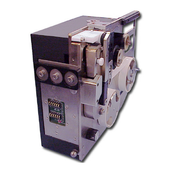
Introduction 2.9 Switches Next to be discussed is the switch bank found on the PL1200 series-labeling unit. This is found on the top of the labeling unit. The switch bank consists of five switches. Each switch contains an LED indicator as shown in diagram 2.9a. - Page 25 Three or more labels will be dispensed at this point. When the PL1200 series-labeling unit is powered up, the ‘STOP’ switch is pressed or an error condition is encountered, the LED indicator on the ‘CAL’ switch will start blinking. This is to alert the operator that a calibration sequence needs to be performed.
- Page 26 PL1200 Thermal Transfer Printer Introduction With the ‘SHIFT’ switch depressed and while concurrently depressing the ‘LABEL ADVANCE’ switch, the print on the label can be adjusted forward in approximately .005-inch increments. With each depression of the ‘LABEL ADVANCE’ switch, an additional increment will occur.
-
Page 27: Chapter 3: Installation
Installation... -
Page 28: Installing The Pl1200 Docking Station
Installation Chapter 3: Installation This chapter will cover the installation of the PL1200 labeling system to the host machine, installation of the software needed to operate the PL1200 labeling unit and how to connect the PRO Labeling 1200 labeling unit to your PC. -
Page 30: Chapter 4: Operations
Operations... -
Page 31: Docking And Removing The Pl1200 Labeling Unit
PL1200 labeling system. 4.1 Docking and Removing the PL1200 Labeling Unit The mounting points on the PL1200 labeling unit consist of a dock clamp block, a guide plate pin and a tooling ball. Please see diagram 4.1a below. -
Page 32: About Changing Media Reels
Before label media reels can be changed and for ease of changing thermal transfer print and label tape, always remove the PL1200 labeling unit from the docking station. Once removed, lay the labeling unit on its back. This makes it easier to handle the label media reels. Before the reels can be removed, the drive arm ‘lock knob’... - Page 33 PL1200 Thermal Transfer Printer Operations To set the knob to the open position, hold the unit firmly by the handle and pull the drive arm ‘lock knob’ out. While holding the knob in the out position, pull the knob to the left until the drive arm locks open.
- Page 34 PL1200 Thermal Transfer Printer Operations Ribbon feeds onto Ribbon feeds from top of take up reel top of stock reel Diagram 4.2c Labels feed from Labels feed onto top of stock reel top of take up reel...
-
Page 35: Installing The Label Media Reels
PL1200 Thermal Transfer Printer Operations Installing the Label Media Reels To install a label media reel, set the drive arm ‘lock knob’ to the ‘open’ position (see section 4.2 of this chapter for instructions) and snap the pressure clips on the ‘stock’ and ‘take up’ label mandrels to the open position. - Page 36 PL1200 Thermal Transfer Printer Operations Lift the ‘label deck’ and run the label leader over the roller at the top of the ‘transfer roller arm’ and bring it down between the ‘transfer roller arm’ and the ‘drive arm’ assembly as shown in diagram 4.3b...
-
Page 37: Removing The Label Media Reels
PL1200 Thermal Transfer Printer Operations Removing the Label Media Reels To remove the label media reels from the mandrels, place the drive arm ’lock knob’ to the open position (see section 4.2 of this chapter) and snap the pressure clips on the ‘stock’ and ‘take up’... - Page 38 PL1200 Thermal Transfer Printer Operations Feed the Take up tape between mandrel these two parts Stock mandrel Diagram 4.5a Next, feed the tape up and over the ‘print head cover’ and onto the ‘take up’ mandrels shown in diagram 4.5a.
-
Page 39: Removing The Thermal Transfer Media Reels
About the Calibration Sequence When the PL1200 is mounted to the docking station it will power up. At power up the calibration LED flashes on the ’CAL’ switch indicating that the operator needs to perform a label calibration... -
Page 40: About Label Positioning Logic
Calibration is required and must be performed any time one of the following occurs; the drive arm has been opened and the label or print media reels have been changed, the PL1200 labeling unit has been mounted or removed from the docking station causing a power off/on sequence, when a calibration, label alignment or tape out error has occurred (please refer to Chapter 2 –... -
Page 41: Chapter 5: Maintenance
Maintenance... -
Page 42: Rollers
The PL1200 labeling system requires very simple maintenance to keep it running smoothly. Please follow the instruction below. 5.1 Rollers It is important to keep the rollers on the PL1200 clean at all times. The Roller locations are shown in diagram 5.1a. There are rollers... -
Page 44: Chapter 6: Troubleshooting
Troubleshooting... -
Page 45: Print Smudging
‘take up’ mandrels. To adjust the slip clutch tension, remove the labeler from the docking station. Next, remove the cover of the PL1200 labeling unit. Spin the manual advance knob to advance the labels and check the label dispensed for smudging. -
Page 46: Labels Won't Calibrate
Troubleshooting To adjust the slip clutch tension, remove the labeler from the docking station. Next, remove the cover of the PL1200 labeling unit. Spin the manual advance knob to advance the labels and check the label dispensed for smudging. If there is no galling present, clean and grease the mandrel. Re-assemble the mandrel, and then recheck the problem. - Page 47 PL1200 Thermal Transfer Printer Troubleshooting To adjust this sensor, use a screwdriver to turn the potentiometer located on top of the laberer. (see diagram 6.3b). Potentiometer Diagram 6.3b By placing the screwdriver in the slot and turning this will adjust the potentiometer.
-
Page 48: Testing Stock Reel Low Sensors
No Power to the PL1200 when Docked Check the power plug in the wall outlet as well as the power connector to the PL1200 labeling unit. After checking power to the docking station, make sure that the labeler is docked and seated correctly. - Page 49 Schematic -and- Wiring...
-
Page 50: Chapter 7: Schematics And Wiring
PL1200 Thermal Transfer Printer Schematic and Wiring Chapter 7: Schematic and Wiring On the following pages you will find the Schematic and Wiring diagrams for the PL1200 labeling system. - Page 51 PL1200 Thermal Transfer Printer Schematic and Wiring...
- Page 52 Spare Parts, Decommissioning, -and- Product Specifications...
-
Page 53: Recommended Spares Kit
Pressure clips (2 pairs) 1 pair for label mandrels, 1 pair for Print ribbon mandrels • Custom pin-out interconnect cable – 1 each • 28 volt 1.5 amp AC power adapter – 1 each Decommissioning When decommissioning the PL1200 labeling system, place it in its original packaging and return to the manufacturer, Hover-Davis, Inc. -
Page 54: Product Specifications
PL1200 Thermal Transfer Printer Spare Parts, Decommissioning, and Product Specifications Product Specifications Environmental Requirements: Storage temperature should be in the range of 33 degrees F to 120 degrees F. Operational temperatures should remain within the range of 60 degrees F to 200 degrees F. -
Page 55: Chapter 9: Technical Bulletins
Technical Bulletins... - Page 56 This chapter is for any technical bulletins that the factory may issue for the PL1200. Please place all technical bulletins that are issued for the PL1200 from the factory in this section of the manual. This will ensure that the most current and up to date information for this...
Need help?
Do you have a question about the PL1200 and is the answer not in the manual?
Questions and answers