
Subscribe to Our Youtube Channel
Related Manuals for Mac Afric C0632C


Summary of Contents for Mac Afric C0632C
- Page 1 C0632C ( 13X40" Engine Lathe OPERATION MANUAL r<> SUBJE('T >LI T AL1-ERATION \VITI- I < N()TICE CUITIO� DATE: 9/12/2000...
-
Page 2: Table Of Contents
CONTENTS APPLICATION - - - --- - - ------ - · - ----- - --- MAIN TECHNICAL SPECIFICATION - - - - - - - - - - --- - - - ---- HOISTING AND INSTALLATION-- -- -· - --- ----- -- DRIVING SYSTEM - - --------- - - - - -- - - - - - - -- BEARING LIST- ----- - - ----- - ----�... - Page 3 _& WARNING ,., ·, I • � 11. Give . y our work undivided attention. 1. Read and understand the entire instruct i on Looking aro.und, carrying on a manual before operating machine. conversation, and ! " l'iorse-play" are careless acts that can result i n 2.
-
Page 4: Application
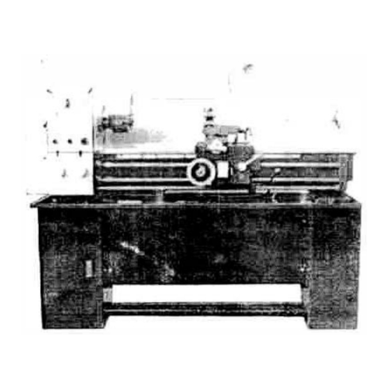
APPLICATION This mach ne is a small-scale universal engine lathe. It can perform various turning as well as boring, drilling, grooving and other operations, i t can also be used for turning metric threads and English threads. The machine is characterized by a simple construction, ah easy operation, large spindle hole and small space occupation. -
Page 5: Hoisting And Installation
Rotary angle of tool post Max. • (76mm) Tool sl i de travel 5 118"(130mm) Cr'6ss slide travel 34" (860mm) Saddle travel 5. Tailstock 1 114" (3 . 2 mm) of taflstock quill No.3 Taper of tailstock quill bore 4" C 00mm) Travel of lailstock qulll Max. - Page 6 Fig. 1 HOISTING CHART ''- ' · 1 �-�- ,, . n Fig. 2 FIXING DIMENSIONS FOR LATHE STAND CABINETS...
-
Page 7: Driving System
DRIVING SYSTEM (Fig. 3) The list of main gears, guide screws and clearance nuts in the machine dri v i n g system No. of PrP.ssur e Part Modulus Material Notes Descrip tion teet h or Parts or pitch angle thread Gear °... - Page 8 No. of Part Modulus Pressure Parts Material Notes Description tee.t h or or pitch angle thread Gear ° Rack ° Single Leadscrew ° thread Single ZQSn Half nut ° thread 6 - 6 -3 Single Worm ° thread ZQSn ° Worm Gear 6 - 6 - 3 °...
- Page 9 -L ' _ � 10 5 r� • <PlJO L� � " � � .r:::::: .::r:::1 �I ".LJJ � • ; 1 ,( , 1 �,� ,,. , Jl ::.J O L(sl � 2 - 80103 .."r 3 3 3� 3( �...
-
Page 10: Bearing List
BEARING LIST (Fig. 4) Installation Name Specification Type Qty' Single row ball bearing 20X42X12 60104 with shield Si• , gle row ball bearing 25X47X12 60105 with shield Single row ball bearing 20X42X12 25X47X15 Single row ball bearing 20X47X14 Single row ball bearing Headstock Single row ball bearing 20X52X15... - Page 11 "' " <, --� � � " ' "- � � � � <t change gea1 • �1 . 8 .
-
Page 12: Lubrication
LUBRICATION �· Head stock - Oil must be up to indicator Mark In oll sight glass (1,Fig 5). Top off with Shell v_!9r-• Fill by removing plug with -an 8mm hex wrench (2, Flg. 5). To drair i. Turbo T-68 or equ drain plug on remove "... - Page 13 ·• II� • • • Fig. 5 LUBIRCATION CHART...
-
Page 14: Electrical System Explanation
ELECTRICAL SYSTEM EXPLAINATION • The machine should be wired correctly according order • E l ectrical control box is located behind the headstock • Power is connected properly when pulling up the forward-reverse lever causes the spindle to rotate counter-clockwise as viewed from the tailstock •... -
Page 15: C Ontrol
CONTROLS 1. Control Panel - located on front of headstock. A. Emergency Stop Switch (1, F 7 ) - depress to stop all machine functions. Twist to restart B. Jog Switch (2, Fig. 7 ) - depress. and re l ease to•advance spindle momentarily. C. - Page 16 13'. Tool Post Clamping Lever (16, Fi g . 7) - located on top of the tool po, s l. Rot11te counter- clockwi s e \o loosen and c l ockwi s e to ti g hten. Flg. 7)- hex socket cap screw located on the si d e of compound Compound Rest Lock ( 17, rest.
- Page 17 [--.·� • • ::1 . J -. � \ . : ._ ; , ; � ,- ·1 � · . · - · • 1 , _ ._ •;., ..,;r • · c.�- "! - .• .. CJ ·-i �;...
- Page 18 ·�••O Feed Rote Table ./\/WWI/ (.'J POSIT (::4 (I 0208 0168 · 1 0.0320 0.0�88 0 .0360 0452 0508 • JW,, 0.0056 0.0099 0.()110 0138 0.0079 � - 0,0084 0104 0.01 0,0124 018 0 0. OlBO • (), 0 .2 5 1 0 .0226 Q.0203 JW,,...
- Page 19 • -· "T1 ,fii f..1 � ..� �lE§ 9 �-- 1 _ ,.., -:.,,, � - ... - ... __ :� : 1: 1; j_ � ; ; ,..,c: :z - - - - :;, � tt.,..; - s: �...
-
Page 20: Accessories
ACCESSORIES '--- Fig.13 STANDARD ACCESSORIES FOR THE MACHINE (shown in Fig. 13) 1. tool rest wrench 7.open-ended wrench sets • 2. wrench for 3-jaw chuck 8.hex wrench sets 3. dead ce . n ts,s M fNO. 3 # reverse jaws kr 3 - jaw chuck screw driver 1 0 .stool box... -
Page 21: Break - In Procedure
BREAK�NPROCEDURE • During manufacturing and test i ng, i s lathe has b. e en operated at low spind l e speed range for three hours. • The machine is equipped with 2 V-belts between the motor pulley and the rear pulley. -
Page 23: Damagebale Parts
DAMAGEABLE PARTS Name Material Qt y' Notes Cross Feed Nut ZQSn6-6-3 5104 Half Nut ZQSn6- 6 -3 4003 ,. - ,A. ¢12 .&. o ,s j J..loo,ej �b IY6-7Hdep12 0 5XA5• '1"' � "' • "' �O • � ui \' ·... - Page 24 4-<P �- ' ' ' 'x----, ' '-" •• - .,, "' � & I;; & � & �- ' · � "'i 1 "- "' �� "' '° ," Appendix Fig. 2 Half Nut Material ZQSn6-6-3 .• · 2 I .
Need help?
Do you have a question about the C0632C and is the answer not in the manual?
Questions and answers