Table of Contents
Advertisement
Quick Links
Advertisement
Table of Contents

Subscribe to Our Youtube Channel
Summary of Contents for Eanmay ST-VGT
- Page 1 TCP/IP&GSM Home Alarm Control Panel Instruction Manual ST-VGT...
-
Page 2: Table Of Contents
Brief Chapter I Product Introduction Chapter II Installation and Connection 2.1 Box Included 2.2 Installation For the Alarm Control Panel 2.3 Connection( The wired zones support N.O. N.C detectors) 2.4 Install wired detector 2.5 Install wireless detector Chapter III Key description and Basic operation 3.1 Key description 3.2 Basic operation 3.3 LCD Icon... - Page 3 6.5.2 set entry delay 6.5.3 set exit delay 6.5.4 set siren time 6.5.5 set detector loss inspection 6.5.6 set arm/disarm tone 6.5.7 set arm/disarm report 6.5.8 set emergency alarm siren type 6.5.9 set others 6.5.9.1 set force alarm 6.5.9.2 set AC off inspection time 6.5.9.3 enable magnetic contact inspection 6.5.9.4 check wireless detector tamper 6.5.9.5 set zone alarm times...
- Page 4 6.6.5.2 delete wireless siren 6.6.6 set door bell 6.6.6.1 enroll door bell 6.6.6.2 delete door bell 6.7 Set Zone 6.7.1 set zone attribution 6.7.2 set zone siren type 6.7.3 set related zone 6.7.4 set RFID tag function 6.8 System Maintenance 6.8.1 set timing arm/disarm 6.8.2 recording 6.8.3 play recording...
- Page 5 7.5 System Options 7.6 Voice Phone 7.7 Wireless Device 7.8 Zone Setting 7.9 RFID Setting 7.10 Event Log 7.11 Remote Upgrade 7.12 System Reboot 7.13 Alert Setting 7.14 Email Setting 7.15 Time Setting 7.16 Home Automation Chapter VIII Mobile APP Management 8.1 enter into the app 8.1.1 local account 8.1.2 Platform account...
-
Page 6: Brief
Brief Thank you for purchasing the “smart home” products of our company, we hope our products can bring convenience and and protection for your safety! The “smart home” system uses the most advanced digital sensing and control technology, it is a set of smart alarm control system of anti-theft,anti-fire, and anti-gas leak compatible with wired and wireless alarm. -
Page 7: Chapter I Product Introduction
Chapter I Product Introduction 1. Alarm mode: with Internet Network and GSM network alarm, GSM network with GPRS function, remote arm and disarm panel through CMS or SMS. CID protocol, SMS notification, the priority of Internet Network and GSM Network is Optional. 2. - Page 8 15. Enable enroll total 8 wireless remote, 16 electronic switch, 1 wireless doorbell and unlimited for quantity of one way wireless siren, 1 wireless two way siren, 16 RFID tags. 16. 6 follow me phone#(voice alarm receiving phone#), 2 for CMS, 4 for private alarm receiving.
- Page 9 alarm when triggering tamper switch at the back of the panel. 28. CMS communications test: The panel will send a message to CMS at the pre-set time interval to inspect the communication if normal. 29. Siren options: Built-in siren, external wired siren, Wireless siren. All sirens can be programmed as enabled/disable when alarms.
-
Page 10: Chapter Ii Installation And Connection
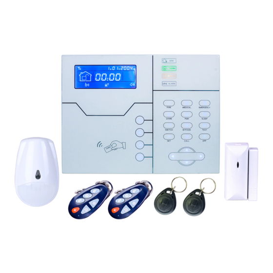
Chapter II Installation and Connection 2.1 Box Included Alarm Control Panel*1pc Wireless PIR Detector*1pc Wireless Door Sensor*1pc Remote Controller*2pcs Battery CR123A*2pcs Power Plug 15/2A RFID Tag*2pcs Components Bag Instruction Manual 2.2 Installation For the Alarm Control Panel 1.Fix the bracket to the wall and hang the panel to the bracket 2.The large metal objects can not be placed around the panel, so as not to affect the wireless signal. -
Page 11: Connection( The Wired Zones Support N.o. N.c Detectors)
2.3 Connection( The wired zones support N.O. N.C detectors) As pictures Here only introduce the zone 33, 34, 37, 38. The other zones please refer to the above. 2.4 Install wired detector 2.4.1 The wired zones is disabled as factory default. when to use wired zones please enable the zones firstly. -
Page 12: Install Wireless Detector
2.5 Install wireless detector 2.5.1 As the detector ‘s manual says, install coded detector in the area 150m from the control panel. Please make the walk testing and make sure detector can work with control panel normally. 2.5.2 Wireless repeater function: (product item No.PB-205R) when wireless detector is too far from the panel or some wall blocked up between panel and detector which disable the panel receive the signal from wireless detector. - Page 13 Light on under armed status, light flashes under stay status Light on under disarmed status Light flashes under AC loss, Zone faulty. Long light under normal working( without any zone faulty) Light flashes when alarm Home Arm Disarm Inquiry Arrow keys( page down, page up, previous,confirm) Up and down button can adjust the voice volume RFID card Press 3 seconds to trigger fire alarm...
-
Page 14: Basic Operation
Press 3 seconds to enter or exit sleep mode Press 3 seconds then enter user code to enable or disable electrical power switch Press 3 seconds then enter user code to bypass zones or activate zones Press 3 seconds then enter user code to proceed normal testing, siren testing and walk testing Press 0 for 3 seconds to make phone call through GSM, the talk time up to approximately 240 seconds... -
Page 15: Lcd Icon
User 02-16 Blank (can not enter the user setting) Disarm User password [1234 ]+Disarm Home Arm Press home arm key Press arm key Event log Inquiry Key Shutdown Press * and hold for more than 3 seconds+user password operation [1234] (AC power-off status) Enter system Press * and hold for more than 3 seconds + admin password operation... - Page 16 flashes when internet loss, light on when internet is normal Flashes when GSM not ready, light on when GSM is normal flashes when GPRS or internet disconnected with CMS, light on when GPRS is connected with CMS. flashes under sleep mode, light on under normal working mode. Zone 5 Alarm Zone 5 detector lost Zone 5 trouble...
-
Page 17: System Arm And Disarm Operation
3.4 System Arm And Disarm Operation Press the arm key on remote or the Press the disarm key on the remote or keypad, then you hear system armed, enter your user password on the please exit the protection area there will keypad,then you will hear Di-Di and be Di-Di sound to confirm the system is voice ‘system disarmed’, then you have... - Page 18 Note: Above operation is arm/disarm by the remote controller. If user receive the SMS from the mobile.it will indicate the code first as below. Different way to arm/disarm, the CMS alarm center and SMS will display the below code and let you know which ways to arm/disarm the system. 40-47 The alarm system can work with 8 remote controller.
-
Page 19: Alarm Procedure
3.5 Alarm Procedure... -
Page 20: Chapter Iv Voice Alarm Receiving And Gsm Control
Chapter IV Voice Alarm Receiving And GSM Control 4.1 Remote Phone Control User make phone call to the GSM No. Of the alarm control panel. Directly connect to the alarm control panel, according to the voice prompt to input the password as below photo. -
Page 21: Gsm Remote Operation
3.Play the recorded voice message first. Press 1 to cancel alarm Press 2 to check alarm event Press 3 to arm system Press 4 to disarm system Press 5 to stay arm 1. The alarm control 2. The user pick up the Press 6 to enable siren panel dial preset voice phone. -
Page 22: Gsm Alarm Receiving
4.4 GSM Alarm Receiving (on-site intercom added) When alarm occurs, it will send SMS first, then call the preset voice number, when pick up the call, it will play the recorded voice message first, then voice prompt: Press 1 to cancel alarm, Press 2 to check alarm event, Press 3 to arm system, Press 4 to disarm system,... -
Page 23: Chapter V User Settings
Chapter V User Settings Press[ * ] for 3 seconds Set system clock Set user password Set voice phone 5.1 Set System Clock For example: set system clock as : 22:59:36 22/12/2012 Please enter system clock,press confirm Press [*] for 3 seconds key to save,press 1 2 3 4 Enter password... -
Page 24: Set Voice Phone
Chapter VI System Settings Press [ * ] for 3 seconds Set password Set network 0 1 2 3 4 5 Set CMS number Set voice phone Set system options Set wireless devices Set zone System maintenance Set other options 6.1 Set Password Press [*] for 3 seconds. - Page 25 Note: 1. password setting include “user password” and “ administrator password”, user password mainly use to disarm the system, it is a private key for remote controlling, “administrator password” is the sole password to set the system. 2. Administrator password is 6 digit, user password is 4 digit, can set 16 user passwords, corresponding password No.
- Page 26 Set network 2.set 3.set 1.Set 4.set 5.set 6.set 7.set network network network network network network network gateway mask CMS IP account password port Please enter Please enter Please enter 5-digit port 8-digit CMS 8-digit CMS Please enter Please enter data,press password.pr account 12-digit subnet...
-
Page 27: Set Network
Set network 1.set 2.set 3.set user 4.set 5.set CMS communication phone phone dialing test interval time No.1 No.2 times please enter phone Please enter please enter please enter number, press * key to phone No. Press communication dialing times, delete, Press confirm * key to inspection interval press confirm... -
Page 28: Set Voice Phone
6.4 Set Voice Phone Press[*] for 3 seconds *012345#4# Set voice phone 1.set 2.set 3.set 4.set 5.set voice 6.set voice phone phone pwd voice voice voice voice dialing inspection phone 1 phone 2 phone 3 phone 4 times 1.Enable please enter phone please enter dialing times. -
Page 29: Set System Option
6.5 Set System Option Press[*] for 3 seconds Set system clock Set entry delay 0 1 2 3 4 5 Set exit delay Set siren time Set detector loss inspection Set arm/disarm tone Set arm/disarm report Set emergency alarm siren type Set others 6.5.1 set system clock. - Page 30 6.5.3 set exit delay Exit Delay: it refers to the period which allows users to exit the zone before arming is activated after setting arm manually or by remote controller, default setting is 10 seconds. Example: set exit delay as 20 seconds. Press [*] for 3 seconds Enter password 3 4 5...
- Page 31 Example: set the detector loss inspection time is 8 hours. Press [*] for 3 seconds. Enter password 3 4 5 Please enter 0 to 99 hours detector loss inspection time, 0 for disable,press confirm key to save,press back key to exit. 6.5.6 set arm/disarm tone When user arm/disarm the alarm control panel by the remote controller whether enable or disable the built-in siren tone of the alarm control panel.
-
Page 32: Set Emergency Alarm Siren Type
6.5.8 set emergency alarm siren type (Default setting is mute) Example: set emergency alarm siren type is pedal point Press[*] for 3 seconds Enter password 3 4 5 Please choose zone siren type: 1.pedal point 2.pulse tone 3. Mute,press confirm key to save,press back key to exit. - Page 33 6.5.9.2 set AC off inspection time When AC loss, delay time of sending the report to the CMS. Default setting is 30 ( minutes. 0-255 minutes for setting) Press [*] for 3 seconds Enter password 3 4 5 Please enter 0 to 255 minutes AC off duration time, press confirm key to save,press back key to exit.
-
Page 34: Set Wireless Device
6.5.9.5 set zone alarm times Before clear alarm or disarm, if set alarm times is 3, when you trigger to alarm again, the alarm control panel will not make alarm. Example: set zone alarm times is 3 times. Enter password 3 4 5 Please choose zone alarm times: 1. -
Page 35: Enroll Remote Controller
6.6.1 set remote controller Press [*] for 3 seconds 0 1 2 3 4 5 Enroll remote controller Enter remote control code Delete remote control 6.6.1.1 enroll remote controller Example:enroll the remote controller to the serial No.3. Enter password 3 4 5 Please enter the serial number of Please trigger the remote control, press confirm key to... -
Page 36: Delete Remote Controller
6.6.1.3 delete remote controller Example: delete the serial No. 5 one. Enter password 3 4 5 Please enter the serial number of remote control to delete, enter 0 to delete all, press confirm key to save,press back key to exit. 6.6.2 set detectors Press [*] for 3 seconds 0 1 2 3 4 5... -
Page 37: Delete Detector
Enter password 3 4 5 Please enter detector Please enter detector No., code, press confirm key press confirm key to to save,press back key save,press back key to exit. to exit. 6.6.2.3 delete detector Example:delete the serial No.3 detector Enter password 3 4 5 Please enter the serial number of detector to delete, enter 00 to delete... -
Page 38: Set Appliance Switch
After enroll RFID tag success. Please set the RFID tag function to make in valid. Refer to the manual 6.7.4 6.6.3.2 RFID tag delete Example: delete the serial No. 2 RFID tag. Enter password 3 4 5 Please enter the serial number of RFID tags to delete, enter 00 to delete all, press confirm key to save,press back key to exit. -
Page 39: Enroll Wireless Siren
Enter password 3 4 5 Please enter the serial number of appliance switch to delete, enter 0 to delete all, press confirm key to save,press back key to exit. 6.6.5 enroll wireless siren Press [*] for 3 seconds 0 1 2 3 4 5 Enroll wireless siren Delete wireless siren 6.6.5.1 enroll wireless siren... -
Page 40: Delete Wireless Siren
display the zone No.41 alarm from the alarm control panel. One alarm control panel only can enroll one dual way wireless siren. The single wireless siren have no quantity limited for enrolling. 6.6.5.2 delete wireless siren Press [*] for 3 seconds Enter password 3 4 5 Delete wireless siren,press confirm... -
Page 41: Set Zone
6.6.6.2 delete door bell Press [*] for 3 seconds Enter password 3 4 5 Delete doorbell,press confirm key to save,press back key to exit. 6.7 Set Zone Press [*] for 3 seconds Set zone attributions Set zone siren type 0 1 2 3 4 5 Set related zone Set RFID tag function 6.7.1 set zone attribution... - Page 42 emergency zone, 24 hours zone, fire zone will trigger alarm when system at any status wireless zone can not set key zone type. When wired zone is set as key zone, trigger the zone, system turn to disarm status. The zone restore, system turn to armed status.
-
Page 43: Set Related Zone
6.7.3 set related zone ( Support 8 Group Of Related Zone) Formula: Zone1 + Zone 2 + related time + Mode 1. Dual trigger alarm mode *Single trigger zone 1 or zone 2, do not alarm. * trigger zone 1 or zone 2 separately within the related time, zone 1 and zone 2 alarm. -
Page 44: Set Rfid Tag Function
6.7.4 set RFID tag function Example: set serial No. RFID tag 2 function is disarm the system and send the message to the users. The SMS must be preset in the web IE settings. Enter password 3 4 5 Enter the serial number of Please set RFID tag function RFID tag, press confirm 1, Disarm 2, Disarm then stay arm 3... -
Page 45: Recording
Enter password 3 4 5 Please enter timing arm time, Please enter timing arm/disarm 00 is invalid time,press confirm group No.,press confirm key to key to save,press back key to save,press back key to exit. exit. Setting is saved. Please enter timing disarm time, 00 is invalid time,press confirm key to save,press back key to exit. -
Page 46: Delete System Log
alarm output options as below. set below 1.Follow alarm output 2. Follow AC power fault output 3.Follow arm output 4, Follow disarm output 5, Follow Communication fault output 6. Password control output Example: set PGM output port follow the password control output. Enter password 3 4 5 Please select PGM output port follow event... -
Page 47: Advanced Setting Options
After restore to factory fault setting. All the wireless devices need to reset and enroll the parameter to alarm control panel again. 6.9 Advanced Setting Options( Without Voice Prompt) The programmable address (50-99) is alarm events. SMS Language Settings Home Arm Boot Voice Volume System Low Battery LCD Standby Lightness... - Page 48 CMS+Voice Phone CMS+SMS Voice Phone+SMS CMS+Voice Phone+SMS Email CMS+Email Voice Phone+Email CMS+Voice Phone+ Email SMS+Email CMS+SMS+Email Voice Phone+SMS+Email CMS+Voice Phone+SMS+Email Make a example When AC loss, user want to receive the message only. From above programmable address table, find the AC loss belongs to 62, and data is 5, send the message to user and report the alarm info to the CMS.
-
Page 49: Gsm Message Language
6.9.1 GSM message language 0 Chinese 1 English Example set GSM message language is English. Enter password 0 1 2 3 4 5 Note: after the alarm control panel do the operation of the restore the factory setting. The GSM message back to Chinese. Please change to English as below operations. 6.9.2 boot voice volume (level 1-8) Example: make the voice volume is 8. -
Page 50: Gsm Spk
6.9.5 GSM SPK (01-99 for options,factory default setting is 60) Example: set GSM SPK is 50. Enter password 0 1 2 3 4 5 6.9.6 GSM MIC (01-07 for options, factory default setting is 01) Example: set GSM MIC is 07 Enter password 0 1 2 3 4 5 6.9.7 door bell voice options... -
Page 51: Alarm Network Receiving Center Connection
6.9.9 alarm network receiving center connection(0 disable, 1 enable) Example enable the alarm network receiving center Enter password 0 1 2 3 4 5... -
Page 52: Chapter Vii Web Ie Introduction
Chapter VII Web IE Introduction Open the IE browse and input the IP address of the alarm control panel, please enter the user and password. Default user account is admin, and password is 012345. Open the internet browse as below photo. -
Page 53: Remote Control
7.1 Remote Control Press the remote control icon to enter below interface. System Status: including system arm, system disarm, system stay, cancel alarm. Zone Bypass: do not let the faulty zone without affecting the normal use of other zones. User can bypass the faulty zone. Zone: 1-40 for options Bypass: Enable/Disable for options After zone bypass enable success. -
Page 54: Password Setting
7.2 Password Setting Enter the password setting, including web admin, web user, panel user password setting. 7.3 CMS Setting... - Page 55 CMS Phone: It can set 2 CMS phone No. After choosing the enable CMS phone, it will report the alarm info to the CMS alarm center machine. Network CMS: If choose enable network CMS, it need to build up own server system and Meian software to operate.
-
Page 56: Network Setting
will report to the Network CMS instead of CMS phone. 7.4 Network Setting It can set the alarm control panel’s network info as below. Pls refer to the 6.2 7.5 System Options It can set entry delay, exit delay, siren time, detector loss, AC off inspection time, communication test, arm/disarm tone and report. -
Page 57: Voice Phone
7.6 Voice Phone Please refer to the manual 6.4. -
Page 58: Wireless Device
7.7 Wireless Device It can set remote controller, detector, appliance switch. 7.8 Zone Setting It can set up zone attribution and related zone. Zone attribution configure please refer to manual 6.7 Related Zone please refer to the manual 6.7.1 Note: Key zones only can set from wired zones 33-40. -
Page 59: Rfid Setting
7.9 RFID Setting It can set the RFID’s enroll, delete, and functions from 01-16 tags. 1, Disarm 2, Disarm then stay arm 3 Disarm and send SMS 4, Stay arm and send SMS 5, Disarm and call voice phone number 1 Note: If user choose the RFID tag function as disarm and send SMS. -
Page 60: Event Log
7.10 Event Log It can inquiry the latest 512 event log. If user want to delete the event log, please enter into the 6.8. 5 delete system log. -
Page 61: Remote Upgrade
7.11 Remote Upgrade Warning: Error of the upgrade file will bring disastrous consequences to your device, please be careful operation! If there is a upgrade error please contact us. The upgrade file is devided into application and webpage file. An upgraded operation need all or part of the files. - Page 62 Note: in the process of the upgrading, it will show the percentage of the process. please do not close the web page and power off the computer. After upgrading success, please restart the alarm control panel. For the upgrade file, please contact us.
-
Page 63: System Reboot
7.12 System Reboot Including system reboot and restore to factory default setting. 7.13 Alert Setting... -
Page 64: Email Setting
7.14 Email Setting 7.15 Time Setting 1. Server Time: China national center for time: 210.72.145.44. US Standard for time: time.nist. gov. 2. Timing Arm/Disarm: Support 4 Groups, please refer to the manual 6.8 Note: The alarm control panel can auto compare the time per 24 hours. -
Page 65: Home Automation
7.16 Home Automation It can set 16CH appliance switch. -
Page 66: Chapter Viii Mobile App Management
Chapter VIII Mobile APP Management The alarm control panel support IOS&Andriod mobile remote control. APP NAME: SMART HOME EX Current state:includes [arm] [stay] [disarm] [clear], remote control the alarm control panel’s alarm mode by the TCP/IP network. Module: includes[ zone bypass control] [switch control] [log events] [function settings] [Account information] [system settings] 8.1 Enter Into the App... -
Page 67: Local Account
8.1.1 Local Account First, create the local account Name: the name of the alarm control panel. User name: the admin user name of the alarm control panel. Password: the alarm control panel’s admin password. IP address: the IP address of the alarm control panel. - Page 68 Note: Before enter into the mobile app. User have to input the IP address and port configuration. For the local account, it have two ways to connection. 1. Wan -LAN(mobile is 3G/4G network. Alarm control panel is LAN network) * If need the WAN access to LAN network. Need to make the port mapping from the Router.
-
Page 69: Platform Account
8.1.2 Platform Account Need the Meian software to control. Please contact sales person from our Meian company. 8.2 Zone Bypass Control When one of the zone faulty and can not enforce arm the system. Check the zone bypass list and can bypass the faulty zone. 8.3 Log Events inquiry the alarm control panel’s alarm log events. -
Page 70: Function Settings
8.4 Function Settings. First enter into the function setting have to set the gesture password. - Page 71 Includes: center platform, network, system setting, phone setting, wireless device, zone setting, RFID settings, alarm settings. GPRS settings, protection settings, email settings, time settings. Function similar to WEB IE and alarm control panel setting.
-
Page 72: Chapter Vxi Technical Specification
Chapter VXI Technical Specification General information 1.Power supply: 15V/2000mA 2.Built in rechargeable battery:11.1V/1000mah 3.System static current: <50mA(exclude wireless detector) 4.System alarming current: <300mA(exclude wireless high siren current) 5.System maximum output current: ≤100mA(supply wireless detector) 6.Frequency:433MHz/868MHz 7.Signal transmit distance: 100 to 150 meters (open area) 8.The method of alarming dial: DTMF GSM or GPRS 9.Communication protocol with CMS: Ademco Contact ID 10.DTMF dial frequency variation:,1.5%... -
Page 73: Chapter Vxii Maintenance
Chapter VXII Maintenance 10.1 Regular Test Design of components of the system is to reduce maintenance cost, but still it is suggested that periodical check may be carried out. 10.2 The Cleanliness of Control Main Machine Main control panel may be stained by fingers or covered by dust after using for a while. - Page 74 MEIAN DEMO P AND E ELECTRONICS HK LIMITED http://www.pe-security.com SHENZHEN MEIAN TECHNOLOGY CO., LTD http://www.meiantech.com No.32, Lanshui Rd, Meian Industrial Park, Longgang District, Shenzhen City, China. postal code: 518116 Phone: +86-755-84844181 Fax: +86-755-84844464 http://pesecurity.en.alibaba.com http://www.globalsources.com/meian.co Demo Video :http://i.youku.com/meiantechnology...
Need help?
Do you have a question about the ST-VGT and is the answer not in the manual?
Questions and answers