
Summary of Contents for Ceragon FibeAir RFU-C
-
Page 1: Installation Guide
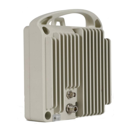
FibeAir® RFU-C Installation Guide Part ID: BM-0133-0 Doc ID: DOC-00017708 Rev M September 2014 Copyright © 2014 by Ceragon Networks Ltd. All rights reserved. - Page 2 Installation Guide Notice This document contains information that is proprietary to Ceragon Networks Ltd. No part of this publication may be reproduced, modified, or distributed without prior written authorization of Ceragon Networks Ltd. This document is provided as is, without warranty of any kind.
-
Page 3: Table Of Contents
7.11 4+0 Dual Polarization – Remote Mount Installation ............. 49 7.12 4+4 Dual Polarization – Remote Mount Installation ............. 52 8. Installing an RFU-C External Attenuator ............57 1+0 Mount Configuration ....................57 1+1 HSB with External Attenuator Configuration ............59 Ceragon Proprietary and Confidential Page 3 of 93... - Page 4 Installing an ALU Melody Adapter ................84 Converting from Nera ODU to RFU-C ................. 88 10. Appendix A: Mediation Device Losses ............92 11. Appendix B: Test Kit Part Numbers .............. 93 Ceragon Proprietary and Confidential Page 4 of 93...
- Page 5 Static electricity may cause body harm, as well as harm to electronic components inside the device. Anyone responsible for the installation or maintenance of the FibeAir RFU-C must use an ESD Wrist Strap. ESD protection measures must be observed when touching the RFU.
- Page 6 Gefahrenrisiko: Durch Abtrennen einer Stromquelle wird nur ein Stromversorgungsmodul abgetrennt. Um die Einheit vollständig zu isolieren, trennen Sie alle Stromversorgungen ab. Maschinenlärminformations-Verordnung - 3. GPSGV, der höchste Schalldruckpegel beträgt 70 dB(A) oder weniger gemäß EN ISO 7779. Ceragon Proprietary and Confidential Page 6 of 93...
-
Page 7: About This Guide
FibeAir® RFU-C Installation Guide About This Guide This guide describes the FibeAir RFU-C installation procedures and provides additional information concerning system parts and frequency bands. What You Should Know RFU-C is a state-of-the-art Radio Frequency Unit which is fully software configurable and supports a broad range of capacities and interfaces. -
Page 8: Important Notes
Acronyms CCDP Co-Channel Dual Polarization Indoor Unit Orthogonal Mode Transducer Radio Frequency Unit Waveguide Cross Polar Differentiation XPIC Cross Polarization Interference Cancellation Ceragon Proprietary and Confidential Page 8 of 93... -
Page 9: Rfu-C Overview
TDM to Ethernet migration, RFU-C works with the FibeAir IP-10G IDU. For Ethernet only, RFU-C works with the FibeAir IP-10E and FibeAir IP-10Q IDUs. Together, FibeAir RFU-C and FibeAir IDUs provide a powerful, reliable, and comprehensive solution for a variety of wireless network scenarios and requirements. -
Page 10: Installing An Rfu-C
ETS 300 019-1-1, Class 1.2. Inspection Check the packing lists and verify that the correct equipment part numbers and quantities are found in the packages that arrived. Ceragon Proprietary and Confidential Page 10 of 93... -
Page 11: Installation Components
Installation Guide Installation Components The following figures show the main components involved in the installation procedures. RFU-C Coupler Remote Pole Mount Remote Dual Pole 4+0/4+4 Extender Remote Mount Twist Remote Mount for 4+0 Ceragon Proprietary and Confidential Page 11 of 93... -
Page 12: Available Adapters And Installation Kits
RFU-C15- RFU-C18-Sym- RFU-C23- COUPLERS KIT cplr-kit Sym-cplr-kit Sym-cplr-kit cplr-kit Sym-cplr-kit RFU-C TWIST KIT RFU-C6- RFU-C7_8- RFU- RFU-C13- RFU-C15- RFU-C18-TWST- RFU-C23_26-TWST-Kit RFU-C28_32-TWST-Kit RFU- RFU-C42- TWST-Kit TWST-Kit C10_11- TWST-Kit TWST-Kit C38- TWST-Kit TWST-Kit TWST- Ceragon Proprietary and Confidential Page 12 of 93... - Page 13 RFU-C WG Kit Flx-WG-4FT- Flx-WG-4FT- Flx-WG-4FT- Flx-WG-3FT- Flx-WG-3FT- Flx-WG-3FT-18-26 Flx-WG-3FT-28-38 Flx-WG- 10_11 3FT-42 RFU-C ADAPTOR TO ADPT_RFU- ADPT_RFU- ADPT_RFU- ADPT_RFU-C18_26-RM_mill ADPT_RFU-C28_38-RM_mill FLEX WG (IMPERIAL) KIT C6-RM_mill ADPT_RFU- C10_11- ADPT_RFU- C15-RM_mill C7_8-RM_mill RM_mill C13-RM_mill Ceragon Proprietary and Confidential Page 13 of 93...
- Page 14 C7_8-RM_mill C10_11- RM_mill C15-RM_mill RM_mill Unique Installations 6GHz 7-8GHz 10-11GHz 13GHz 15GHz 18GHz 23GHz 26GHz 28-31GHz 32GHz 38GHz 42GHz and Accessories RFU-C 19in RFU-C_19-inch_rack_adapt MOUNTING KIT RFU-C External 20dB RFU-C38- Attenuator attn-20 Ceragon Proprietary and Confidential Page 14 of 93...
- Page 15 INT-X INT-X INT-X INT-X OMT-INT-X OMT-INT-X branding) This adapter is not required if the antenna is equipped with a circular feeder. Such antenna will have the following marketing model structure: Am-size(ft)-freq- CIRC-mnf. Ceragon Proprietary and Confidential Page 15 of 93...
-
Page 16: Antenna Connection
UG383/U UG383/U If a different antenna type (CPR flange) is used, a flange adaptor is required. Please contact your Ceragon representative for details. Note: Conductive grease must be applied to the screws that connect the RFU-C to the antenna interface. -
Page 17: Cable Installation And Grounding
20A, shall be installed for full power disconnection in a building installation. Any outdoor antenna cable shield shall be permanently connected to protective earth in a building installation. Ceragon Proprietary and Confidential Page 17 of 93... -
Page 18: Generic Installation Procedures
RFU-C Remote Pole Mount kit using the four flat screws supplied with the RFU-C Adaptor kit. 2 Mount the RFU-C using the four captive screws and washers supplied, assembled, in the RFU-C. Ceragon Proprietary and Confidential Page 18 of 93... - Page 19 1 Mount the RFU-C Adaptor supplied with the RFU-C Remote Pole Mount kit using the four flat screws supplied with the RFU-C Adaptor kit. 2 Mount the RFU-C using the four captive screws and washers supplied, assembled, in the RFU-C. Ceragon Proprietary and Confidential Page 19 of 93...
- Page 20 2 Mount the RFU-C using the four captive screws and washers supplied, assembled, in the RFU-C. 3 Connect the Flexible Waveguide and sealing O-Ring supplied with the Flexible Waveguide Imperial kit. Tighten the four metric screws supplied with the RFU-C Adaptor kit. Ceragon Proprietary and Confidential Page 20 of 93...
-
Page 21: Omt Wg Adaptor Installation
Mount the OMT adaptor, with its installed sealing gasket, on the OMT, and tighten using the four M4 screws and washers supplied with the OMT Adaptor kit. iii Mount the flexible waveguide without its gasket (only for the OMT side). Ceragon Proprietary and Confidential Page 21 of 93... - Page 22 FibeAir® RFU-C Installation Guide 3. For 13 GHz (UBR120) to 42 GHz (UG383/U), connect the flexible waveguide and its gasket (supplied with the Flexible WG Kit) directly to the OMT port. Ceragon Proprietary and Confidential Page 22 of 93...
-
Page 23: Rfu-C Configurations
Important! Do not remove the transparent pressure window located on the antenna interface. Note: If necessary, change the antenna polarization by rotating the RFU-C in accordance with the relevant antenna installation guide. Ceragon Proprietary and Confidential Page 23 of 93... - Page 24 1 Mount the RFU-C on the antenna using the four M8 captive screws and washers that are supplied, assembled, in the RFU-C, and tighten the screws. Note: Make sure the polarization mounting direction of the RFU-C is correct. Ceragon Proprietary and Confidential Page 24 of 93...
-
Page 25: 1+0 Remote Mount Installation
RFU-C, and tighten the screws. 3 Place the O-Ring in the flexible waveguide flange groove. 4 Place the O-Ring in the other end of the flexible waveguide flange groove. Ceragon Proprietary and Confidential Page 25 of 93... - Page 26 FibeAir® RFU-C Installation Guide 5 Mount the flexible waveguide on the antenna, and tighten the screws and washers. Ceragon Proprietary and Confidential Page 26 of 93...
-
Page 27: 1+1 Direct Mount Installation
The gasket should be mounted between the twist and the RFU-C Coupler kit. 1 Mount the twist to the coupler using the O-Ring and four screws supplied in the Twist kit, and tighten the screws. Ceragon Proprietary and Confidential Page 27 of 93... - Page 28 2 Mount the coupler radio on the antenna using the four M8 screws and washers supplied with the RFU-C Coupler kit, and tighten the screws. 3 Mount the two O-Rings supplied with the RFU-C Coupler kit, as shown in the following figure. Ceragon Proprietary and Confidential Page 28 of 93...
- Page 29 FibeAir® RFU-C Installation Guide 4 Mount the RFU-C to the body of the coupler using the four M8 captive screws and washers that are supplied, assembled, in the RFU-C, and tighten the screws. Ceragon Proprietary and Confidential Page 29 of 93...
-
Page 30: 1+1 Remote Mount Installation
1 Mount the RFU-C coupler to the RFU-C pole mount bracket using the four M8 screws and washers supplied with the RFU-C Coupler kit, and tighten the screws. 2 Mount the two O-Rings supplied with the Coupler kit, according to the Coupler kit instructions. Ceragon Proprietary and Confidential Page 30 of 93... - Page 31 5 Mount the flexible waveguide on the coupler, and tighten the screws and washers. 6 Place the O-Ring in the other end of the flexible waveguide flange groove. 7 Mount the flexible waveguide on the antenna, and tighten the screws and washers. Ceragon Proprietary and Confidential Page 31 of 93...
-
Page 32: 2+0 Dual Polarization - Direct Mount Installation
Mylar film on the OMT ports. 1 Prior to the installation, follow the antenna manufacturer’s instructions to switch to circular adaptor (remove the existing rectangular transition, swap the O-Ring, and install the circular transition instead). Ceragon Proprietary and Confidential Page 32 of 93... - Page 33 OMT kit. Do not tighten them yet, to enable rotation of the entire assembly. 3 Mount the two O-Rings supplied with the OMT kit on the OMT body. Make sure the mounting direction is correct, as shown in the section view. Ceragon Proprietary and Confidential Page 33 of 93...
- Page 34 5 Tilt the entire assembly, as described in the XPIC link alignment procedure, to achieve maximum XPD (Cross Polar Differentiation). After link alignment, tighten the four M8 screws left open in step 2 above. Ceragon Proprietary and Confidential Page 34 of 93...
-
Page 35: 2+0 Dual Polarization - Remote Mount Installation
FLEXIBLE WG KIT Optional RFU-C REMOTE MOUNT KIT RFU-C REMOTE MOUNT ADAPTOR KIT For 6 to 13GHz Required Tools Metric offset hexagon key wrench 6 Metric offset hexagon key wrench 3 Ceragon Proprietary and Confidential Page 35 of 93... -
Page 36: Omt Wg Adaptor Installation
OMT WG Adaptor Installation on page 21. 2 Connect the other end of the flexible waveguide to the RFU-C Radio port. Note: For detailed remote mount installation instructions, refer to 1+0 Remote Mount Installation on page 25. Ceragon Proprietary and Confidential Page 36 of 93... -
Page 37: 1+0 Ready For 2+0 Dual Polarization - Direct Mount Installation
1 Place the Plate in front of the coupler holder. 2 Tighten the plate to the upgradable port side with the M8 screws and washers supplied with the RFU-C coupler short plate kit using 21.4 NM torque. Ceragon Proprietary and Confidential Page 37 of 93... - Page 38 FibeAir® RFU-C Installation Guide Ceragon Proprietary and Confidential Page 38 of 93...
-
Page 39: 2+0 Single Polarization - Direct Mount Installation - Symmetrical Couplers
Metric offset hexagon key wrench #2.5, #3 and #6. Procedure 1 Remove the Extender from the Symmetrical Coupler by opening and removing the four M4 screws and washers, as shown in following figure. Ceragon Proprietary and Confidential Page 39 of 93... - Page 40 The gasket should be mounted between the twist and the RFU-C Circulator/Symmetrical Coupler Kit. Important! Make sure the polarization mounting direction of the twist to the RFU-C circulator / symmetrical coupler is according to the antenna polarization. Ceragon Proprietary and Confidential Page 40 of 93...
- Page 41 Coupler using the four M8 captive screws and washers that are supplied assembled in the RFU-C, and tighten the screws. Note: RFU-C mounting screws and washers can be supplied either assembled on the RFU-C, or as a part of the RFU-C Kit. Ceragon Proprietary and Confidential Page 41 of 93...
-
Page 42: 2+0 Single Polarization - Direct Mount Installation - Asymmetrical Couplers
RFU-C units for an even system gain between both channels. Freq1 Freq1 Standard Standard 6.5dB Loss 1.5dB Loss coupler coupler assembly assembly 1.5dB Loss 6.5dB Loss Freq2 Freq2 Couplers are cross – installed to get symmetrical system gain. Ceragon Proprietary and Confidential Page 42 of 93... -
Page 43: 2+2 Dual Polarization - Remote Mount Installation
Mylar film on the OMT ports. 1 Prior to the installation, follow the antenna manufacturer’s instructions to switch to circular adaptor (remove the existing rectangular transition, swap the O-Ring, and install the circular transition instead). Ceragon Proprietary and Confidential Page 43 of 93... - Page 44 (supplied with the Flexible WG Kit) directly to the OMT port. 5 Connect the other end of the flexible waveguide to each RFU-C Coupler port mounted on the RFU-C Dual Pole Remote Mount Kit. Ceragon Proprietary and Confidential Page 44 of 93...
-
Page 45: 4+0 Single Polarization - Remote Mount Installation
Do not remove the transparent pressure window located on the antenna interfaces. 1 Mount the Pole mount brackets, by tightening four M10 screws and washers (supplied with the RFU-C-Remote Mount kit for 4+0). Ceragon Proprietary and Confidential Page 45 of 93... - Page 46 RFU-C Symmetrical coupler by tightening four M8 screws and washers (screws are supplied in the RFU-C Remote Mount Kit for 4+0). Repeat the operation for both RFU-C Symmetrical couplers. Ceragon Proprietary and Confidential Page 46 of 93...
- Page 47 6 Mount the two O-Rings (supplied in the RFU-C Symmetrical coupler kit). 7 Mount the two RFU-C radio units on each RFU-C Symmetrical coupler by tightening the four M8 captive screws and washers (supplied assembled in the RFU-C radio). Ceragon Proprietary and Confidential Page 47 of 93...
- Page 48 8 Connect the flexible waveguide to the RFU-C Symmetrical coupler using the O-Ring and screws (supplied with the Flexible Waveguide kit). Connect the other end of the flexible waveguide to the antenna. Ceragon Proprietary and Confidential Page 48 of 93...
-
Page 49: 4+0 Dual Polarization - Remote Mount Installation
The procedure is similar to the 2+2 dual polarization procedure, except that here, symmetrical couplers are used instead of asymmetrical couplers. Important! Do not remove the transparent pressure window located on the antenna interface or the Mylar film on the OMT ports. Ceragon Proprietary and Confidential Page 49 of 93... - Page 50 (supplied with the RFU-C-Remote Mount kit FOR 4+0). 6 Remove the Extender from the RFU-C symmetrical coupler by opening and removing the four M4 screws and washers. Repeat this operation for both RFU-C symmetrical couplers. Ceragon Proprietary and Confidential Page 50 of 93...
- Page 51 RFU-C remote mount bracket, by tightening the four M8 screws and washers (supplied with each RFU-C Coupler kit). 8 Connect the other end of the flexible waveguide to each RFU-C symmetrical coupler mounted on the RFU-C Remote mount bracket. Ceragon Proprietary and Confidential Page 51 of 93...
-
Page 52: 4+4 Dual Polarization - Remote Mount Installation
Mylar film on the OMT ports. 1 Prior to the installation, follow the antenna manufacturer’s instructions to switch to circular adaptor (remove the existing rectangular transition, swap the O-Ring, and install the circular transition instead). Ceragon Proprietary and Confidential Page 52 of 93... - Page 53 M4 screws and washers. Repeat this operation for both RFU-C symmetrical couplers. 7 Mount the pole mount brackets by tightening four M10 screws and washers (supplied with the RFU-C-Remote Mount kit for 4+0). Ceragon Proprietary and Confidential Page 53 of 93...
- Page 54 M4 screws and washers, as shown in following figure: 9 Mount the RFU-C symmetrical coupler, without the Extender part, to the RFU-C pole mount bracket, by tightening four M8 screws and washers (supplied with the RFU-C Coupler kit). Ceragon Proprietary and Confidential Page 54 of 93...
- Page 55 Mount the two RFU-C symmetrical couplers to the third one. For each RFU-C Symmetrical coupler, use four M8 screws and washers (supplied in the RFU-C Symmetrical Coupler kit). Note: The O-Ring is mounted with the flat bottom facing the coupler. Ceragon Proprietary and Confidential Page 55 of 93...
- Page 56 O-Ring and screws (supplied with the flexible waveguide kit). Connect the other end of the Flexible Waveguide to one radio port polarization of RFU-C OMT. 14 Repeat paragraphs 7 through 13 for the second polarization. Ceragon Proprietary and Confidential Page 56 of 93...
-
Page 57: Installing An Rfu-C External Attenuator
2 Mount the RFU-C External Attenuator to the antenna using the four M8 screws and washers supplied with the RFU-C External Attenuator kit, and tighten the screws. The polarization mounting direction must be the same as that of the antenna. Ceragon Proprietary and Confidential Page 57 of 93... - Page 58 3 Mount the RFU-C to the RFU-C External Attenuator using the four M8 screws and washers supplied with the RFU-C Radio kit, and tighten the screws. The RFU-C radio mounting polarization should be mounted using the same polarization as the RFU-C External Attenuator. Ceragon Proprietary and Confidential Page 58 of 93...
-
Page 59: 1+1 Hsb With External Attenuator Configuration
The polarization mounting direction of the RFU-C Twist must be the same as that of the antenna. 3 Remove the stickers from the RFU-C External Attenuator carefully so that the sealing gaskets remain in place. Ceragon Proprietary and Confidential Page 59 of 93... - Page 60 The polarization mounting direction must be the same as that of the antenna. 5 Mount the RFU-C coupler to the RFU-C External Attenuator using the four M8 screws and washers supplied with the RFU-C Coupler kit, and tighten the screws. Ceragon Proprietary and Confidential Page 60 of 93...
-
Page 61: Installing Rfu-C On Third-Party Antenna Adapters
Special Note on Converting VINTA-6W- VINTA-7W- VINTA-11W- VINTA-28- VINTA-32- VINTA-38- ValuLine 3 Antennas on page 62. VINTA-13-CR4 VINTA-15-CR4 VINTA-18-CR4 VINTA-23-CR4 VINTA-26-CR4 Ceragon Proprietary and Confidential Page 61 of 93... -
Page 62: Special Note On Converting Valuline 3 Antennas
ValuLine 3 antennas, 1-6ft. However, since there are some unique cases in which Andrew provided special antennas which are not supported by these adaptors, it is recommended that you supply your Ceragon representative with a picture of the current antenna (back plain side), in order to confirm the antenna’s compatibility prior to implementing this solution. -
Page 63: Direct Mount For Nsn Flexihopper Antennas
This adapter is for the NSN Flexihopper antenna. List of Items Item Description Quantity RFU-C NSN INTERFACE RFU-C O-RING RFU-C RADIO SCREW SOCKET HEAD M8 WASHER SPRING LOCK FOR M8 Required Tools Metric offset hexagon key wrench 6 Ceragon Proprietary and Confidential Page 63 of 93... - Page 64 2 Insert the O-Ring in its groove at the rear side of the RFU-C. Make sure the mounting direction is correct, as shown in the section view. 3 Insert the four screws and washers supplied with the RFU-C through the RFU-C and NSN adapter, and tighten the screws. Ceragon Proprietary and Confidential Page 64 of 93...
- Page 65 FibeAir® RFU-C Installation Guide The following figure shows the RFU mounted to the NSN antenna. Ceragon Proprietary and Confidential Page 65 of 93...
-
Page 66: Installing An Rfu-P Antenna Adaptor
RFU-C/RFU-P DIRECT MOUNT INTERFACE RFU-C RADIO 1 or 2 RFU-C COUPLER Optional Required Tools Metric offset hexagon key wrench #6 Metric offset hexagon key wrench #3 Screwdriver Phillips #2 Ceragon Proprietary and Confidential Page 66 of 93... - Page 67 2 The RFU-C/RFU-P interface is mounted with vertical polarization by default. If necessary, switch the polarization by releasing four countersink screws, rotating the central adaptor 90 degrees, and re-tightening the screws. Ceragon Proprietary and Confidential Page 67 of 93...
- Page 68 RFU-C kit, and tighten the screws. Note: RFU-C mounting screws and washers can be supplied either assembled on RFU-C, or as a part of RFU-C Kit. Make sure the radio polarization mounting direction is correct. Ceragon Proprietary and Confidential Page 68 of 93...
- Page 69 Coupler kit instructions. Note: For 15 GHz and 18 GHz, an EMI gasket (supplied with the RFU-P interface) should be mounted between the twist and the coupler body. Ceragon Proprietary and Confidential Page 69 of 93...
- Page 70 6 Mount the coupler on the RFU-P interface using the four M8 screws and washers supplied in Coupler kit, and tighten the screws. 7 Proceed with mounting the RFUs, as defined in the Coupler kit instructions. Ceragon Proprietary and Confidential Page 70 of 93...
- Page 71 The gasket is supplied in the RFU-C/RFU-P Direct Mount Interface Kit. 9 Connect the Flexible Wave-Guide using the four M3 screws and washers supplied in the Coupler Kit, and tighten the screws. Ceragon Proprietary and Confidential Page 71 of 93...
-
Page 72: Installing An Rfu-C Adaptor To Ericsson Antennas (Rau1 Radios)
2 Place the RFU-C-Ericsson Adapter Kit for RAU1 on the Ericsson antenna. 3 Tighten the three screws and spring washers supplied in the -C-Ericsson Adapter Kit for RAU1, as shown in the figure below. Ceragon Proprietary and Confidential Page 72 of 93... -
Page 73: Connecting The Rfu To The Ericsson Antenna
1 Mount the RFU to the antenna, using the four M8 captive screws and washers supplied, assembled, in the RFU-C, and tighten the screws. Make sure the polarization mounting direction of the RFU is correct. Ceragon Proprietary and Confidential Page 73 of 93... -
Page 74: Installing An Rfu-C Adaptor To Ericsson 0.3M Compact Antennas (Rau2 Radios)
Connecting the Adaptor Kit to the Ericsson 0.3m Compact Antenna 1 Insert the two lower screws and two spring washers supplied in the Ericsson kit, as shown in the figure below. Do not tighten them! Ceragon Proprietary and Confidential Page 74 of 93... - Page 75 Ericsson antenna lower screws. 4 Insert the two upper screws and spring washers supplied in the Ericsson kit, as shown in the figure below. 5 Tighten the four screws, as shown in the figure below. Ceragon Proprietary and Confidential Page 75 of 93...
-
Page 76: Connecting The Rfu To The Ericsson Antenna
1 Mount the RFU to the antenna, using the four M8 captive screws and washers supplied, assembled, in the RFU-C, and tighten the screws. Make sure the polarization mounting direction of the RFU is correct. Ceragon Proprietary and Confidential Page 76 of 93... -
Page 77: Installing An Rfu-C - Nec Adapter (Pasolink Neo)
3 Fasten the RFU-C - NEC adapter to the NEC Shenglu or Mobi antenna using four screws and four washers. Note: Fasten the screws diagonally. First fasten the upper right screw and lower left screw, and then fasten the upper left screw and lower right screw. Ceragon Proprietary and Confidential Page 77 of 93... - Page 78 FibeAir® RFU-C Installation Guide Attaching the Adapter Plate to an NEC Shenglu Antenna Attaching the Adapter Plate to an NEC Mobi Antenna Ceragon Proprietary and Confidential Page 78 of 93...
- Page 79 RFU-C, and tighten the screws. Note: Make sure the polarization is correct, as shown in the figures below. Attaching the RFU-C to the RFU-C – NEC Adapter – Shenglu Antenna Ceragon Proprietary and Confidential Page 79 of 93...
- Page 80 FibeAir® RFU-C Installation Guide Attaching the RFU-C to the RFU-C – NEC Adapter – Mobi Antenna The figure below shows the RFU-C with the NEC adapter installed (Shenglu antenna option). Ceragon Proprietary and Confidential Page 80 of 93...
-
Page 81: Installing An Rfu-C - Sral Adaptor
2 Make sure the adapter O-ring is in place, as shown in the figure below. 3 Attach the RFU-C to the adaptor by closing the four captive screws and four washers that are supplied, assembled, in the RFU-C, and tighten the screws. Ceragon Proprietary and Confidential Page 81 of 93... - Page 82 Note: Make sure you align the units properly for the horizontal or vertical direction. 6 Fasten the RFU-C and the adapter to the SRAL antenna using the four latches. Ceragon Proprietary and Confidential Page 82 of 93...
- Page 83 FibeAir® RFU-C Installation Guide The figure below shows the RFU-C with the SRAL adapter installed. Ceragon Proprietary and Confidential Page 83 of 93...
-
Page 84: Installing An Alu Melody Adapter
6.0 mm Offset Hexagon Key Wrench Procedure 1 Place the O-ring (supplied with RFU-C ALU Adapter kit) at the center of the transition, so the flat area is facing towards the tube. Ceragon Proprietary and Confidential Page 84 of 93... - Page 85 3 Place the RFU-C Radio on the RFU-C ALU Adapter Kit according to the correct polarization and secure with the four screws and washers (included in the RFU-C Radio kit). Ceragon Proprietary and Confidential Page 85 of 93...
- Page 86 5 Gently place the RFU-C ALU Adapter kit on the ALU Antenna tube's feeder, using the slots to center the RFU-C ALU Adapter Kit with the ALU antenna. Note: Make sure the units are properly aligned with horizontal or vertical polarization. Ceragon Proprietary and Confidential Page 86 of 93...
- Page 87 Installation Guide 6 Latch the RFU-C ALU Adapter kit to the ALU antenna using the four latches. It is highly recommended to secure at least one of the latches with a lock. Ceragon Proprietary and Confidential Page 87 of 93...
-
Page 88: Converting From Nera Odu To Rfu-C
Antenna systems should be inspected once a year by qualified personnel to verify proper installation, maintenance, and condition of equipment. Ceragon disclaims any liability or responsibility for the results of improper or unsafe installation practices. Use protective wear to avoid skin contact with the compound. Keep away from mouth. - Page 89 Make sure that the timing pin is located in the timing recess in the interface plate. 2 Remove the protective tape. 3 Assemble the small o-ring to feed. 4 Smear a small amount of silicon grease onto the O-Ring (two and three feet ONLY). Ceragon Proprietary and Confidential Page 89 of 93...
- Page 90 Rotate the transition assembly until the timing pin is located in the timing recess of the interface plate at the “V” position. iv Re-tighten the c’sk screws to a torque of 10Nm±5%. Ceragon Proprietary and Confidential Page 90 of 93...
- Page 91 “H” position. iv Re-tighten the c’sk screws to a torque of 10Nm±5%. View Showing Full Assembly of Interface Plate and Transition Hub to Reflector Ceragon Proprietary and Confidential Page 91 of 93...
-
Page 92: Appendix A: Mediation Device Losses
Integrated antenna 4+0 DP (OMT) Remote Mount Notes: The antenna interface is always the RFU-C interface. If other antennas are to be used, an adaptor with a 0.1 dB loss should be considered. Ceragon Proprietary and Confidential Page 92 of 93... -
Page 93: Ceragon Proprietary And Confidential
RFU-C7_8-TS/P RFU-C7_8-TS/X 10/11 GHz RFU-C10_11-TS/NP RFU-C10_11-TS/P RFU-C10_11-TS/X 13 GHz RFU-C13-TS/NP RFU-C13-TS/P RFU-C13-TS/X 15 GHz RFU-C15-TS/NP RFU-C15-TS/P RFU-C15-TS/X 18-26 GHz RFU-C18_26-TS/NP RFU-C18_26-TS/P RFU-C18_26-TS/X 28-38 GHz RFU-C28_38-TS/NP RFU-C28_38-TS/P RFU-C28_38-TS/X 42 GHz RFU-C42-TS/NP RFU-C42-TS/P RFU-C42-TS/X Ceragon Proprietary and Confidential Page 93 of 93...
Need help?
Do you have a question about the FibeAir RFU-C and is the answer not in the manual?
Questions and answers