Advertisement
Table of Contents
- 1 Table of Contents
- 2 Description
- 3 Outline Dimension Drawings and Controller Wiring
- 4 Panel Operation
- 5 Installation Guide
- 6 Control and Operation Instruction
- 7 Measure and Display Data
- 8 Pre-Alarm and Shutdown Alarm
- 9 Parameter Settings
- 10 LCD Display and Menu System
- 11 Preparation before Starting the Controller
- 12 Technical Specification
- Download this manual
Advertisement
Table of Contents

Summary of Contents for FG Wilson DCP-10
- Page 1 Manual DCP-10 Genset Controller...
- Page 2 DCP-10 The interpretation of the Symbol: WARNING: A WARNING indicates a potentially hazardous situation which, if not avoided, could result in death, serious personal injury or property damage. CAUTION: A CAUTION indicates a potentially hazardous situation which, if not avoided, could result in damage to equipment or property.
- Page 3 DCP-10 WARNING: Read this entire manual pertaining to the work to be performed before installing, operating, or servicing this controller. Practice all plant and safety instructions and precautions. Failure to follow instructions can cause personal injury and/or property damage. The engine or other type of prime mover should be equipped with an...
-
Page 4: Table Of Contents
DCP-10 Contents 1. Description…………………………………………………………………………………………………… 2. Outline Dimension Drawings and Controller Wiring………………………………………………… 3. Panel Operation…………………………………………………………………………………………… 4. Installation Guide………………………………………………………………………………………… 5. Control and Operation Instruction……………………………………………………………………… 6. Measure and Display Data……………………………………………………………………………… 7. Pre-alarm and Shutdown Alarm………………………………………………………………………… 8. Parameter Settings……………………………………………………………………………………… 9. LCD Display and Menu System…………………………………………………………………………... -
Page 5: Description
DCP-10 1. Description The DCP-10 is an Automatic Controller for generator. When running in “AUTO” mode, it starts the Genset after receiving remote start signal and on failure automatically stops the Genset. The generator’s controlling procedure and protection parameters can be modified, which fully meets the Genset’s requirements of automatic start, stop control and basic protection. -
Page 6: Outline Dimension Drawings And Controller Wiring
DCP-10 2. Outline Dimension Drawings and Controller Wiring 2.1 Following Details: Module Dimensions W120mm×H102mm Panel Cutout W110mm×H92mm Thickness D48mm (without connection) Page 2/27... - Page 7 DCP-10 2.2 Terminal Connections: Pin no. Function Description Signal 1mm² GEN. V input 0-300Vac L1-N 1mm² GEN. V input 0-300Vac L2-N 1mm² GEN. V input 0-300Vac L3-N 1mm² GEN. Neutral Not used Not used 2.5mm² I1 Gen current input 0-5A 2.5mm²...
- Page 8 DCP-10 2.3 Typical Wiring Diagram Fuse protection with a rating of 0.5A must be provided externally to the Controller. Page 4/27...
-
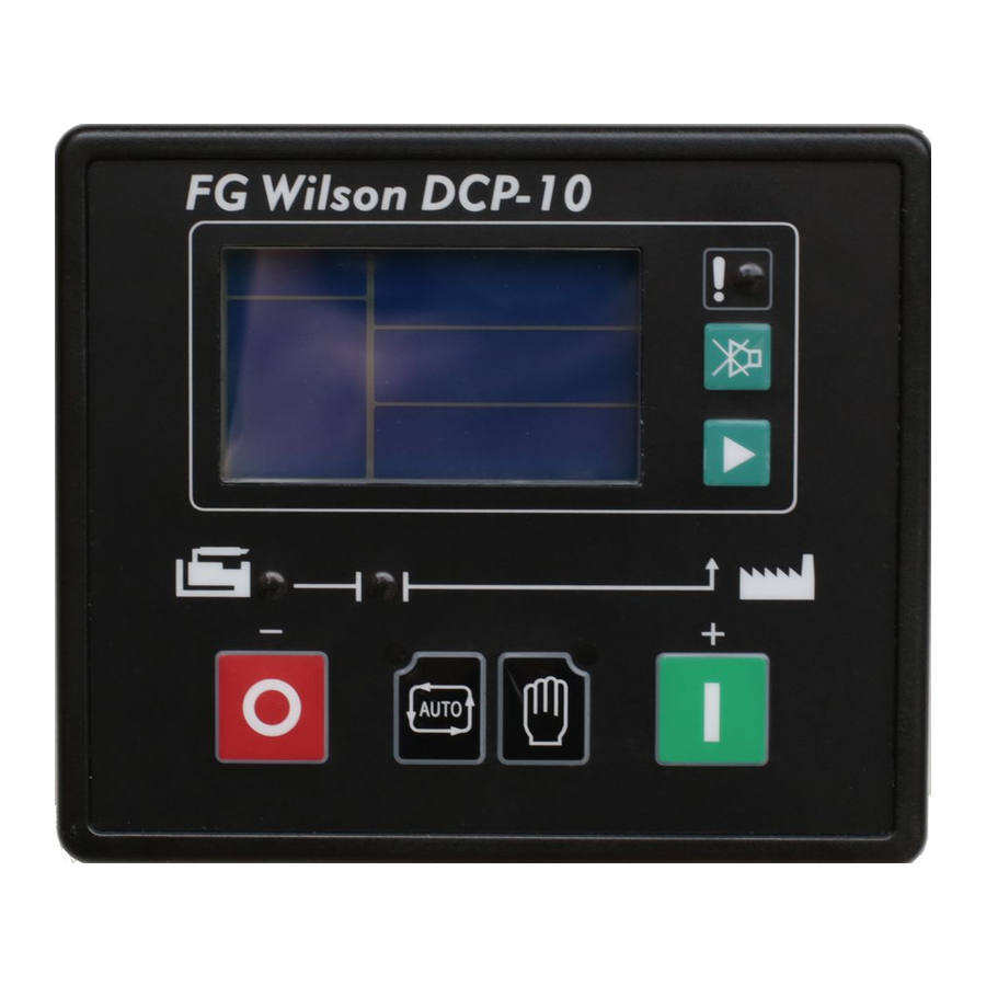
Page 9: Panel Operation
DCP-10 3. Panel Operation The operation panel consists of 3 sections: LCD display indicating measurement parameters, LED indicator for common failure, and push buttons for Genset and selection of control modes. The LCD circularly displays different measuring parameters. When failure occurs, LCD displays the corresponding fault icon. -
Page 10: Installation Guide
DCP-10 4. Installation Guide 4.1 The cutout dimensional drawing installed on panel as above attached. The controller is fixed by 2 special fittings. The shock-proof equipment must be mounted if the enclosure is mounted on Genset or other heavy vibrant device. A readily accessible disconnect device shall be incorporated external to the equipment. -
Page 11: Control And Operation Instruction
DCP-10 5. Control and Operation Instruction 5.1 Operation Mode Setting: The controller has 2 modes: AUTO and MANUAL. Operation Description Press and hold the “AUTO” button for 2sec, the LED above the button is illuminated; the controller is running in “AUTO” mode. - Page 12 DCP-10 NOTE: While cranking, engine ignites. The start motor will power off when the output frequency of generator reaches the preset value (configurable crank cutout value), or if there are one of the following conditions occur: A. Generator’s voltage reaches 80% of rated voltage;...
- Page 13 DCP-10 Stop Failure: When cool down times out, the fuel relay opens and the timer for Stop delay begins. When it times out, if controller detects that the voltage and frequency of generator or oil pressure of engine are greater than the preset values, the Fail to stop LED illuminates and the LCD displays Fail to stop.
- Page 14 DCP-10 5.5 Idle function: For idle function configure one of the configurable outputs as idle. Refer to the flow chart 5.7 for start and stop for idle control flows. 5.6 Preheat function: For Preheat function, configure one of the configurable outputs as Preheat. The controller has 3 selectable preheat control modes as below: Mode 1 —...
- Page 15 DCP-10 5.7 Flow chart for start and stop T1- start delay T4- safety-on delay T2- crank time T5- idle time T3- pre-heat time T6- stop delay NOTE: If T4 is longer than T5, low oil pressure protection is ignored during T5.
-
Page 16: Measure And Display Data
DCP-10 6. Measure and Display Data Gen phase voltage L1-N L2-N L3-N Gen line voltage L1-L2 L2-L3 L3-L1 Generator current I1 I2 I3 Generator frequency Hz Engine speed RPM (signal derived from generator frequency) Engine oil pressure BAR / PSI (signal from engine LOP sensor) Engine coolant temperature ℃/℉... -
Page 17: Pre-Alarm And Shutdown Alarm
DCP-10 7. Pre-alarm and Shutdown Alarm 7.1 Pre-alarm (Warning) NOTE: (Pre-alarms are non-critical failure conditions and do not affect the operation of the generator system, they serve for drawing the operators’ attention to an undesirable condition so they can remove it to ensure continuous running of the system. - Page 18 DCP-10 OVER CURRENT: if any phase output current of generator exceeds the “over current pre-alarm” after the safety-on timer has expired, common failure LED indicator flashes. For example, “over current pre-alarm” preset as: 850A, when any phase output current of generator exceeds this value, LCD flashing high value icon for corresponding phase: GEN.
- Page 19 DCP-10 7.2 Shutdown Alarm NOTE: (shutdown alarm failures immediately lock out the system and stop the Genset. The failure must be removed and the controller reset before restarting the Genset.) Shutdown Alarm / Description LCD Display START FAILURE: if engine does not fire after the preset number of crank attempt has been made, the Shutdown alarm LED illuminates.
- Page 20 DCP-10 Code Table for Failure: Name Code Name Code CHARGE FAILURE ENGINE HIGH TEMP BATT. UNDER VOLT OVER SPEED BATT. OVER VOLT UNDER SPEED START FAILURE OVER CURRENT STOP FAILURE GEN. OVER VOLT EMERGENCY STOP GEN. UNDER VOLT LOW OIL PRESS...
-
Page 21: Parameter Settings
DCP-10 8. Parameters Setting 8.1 System Parameters: Items Preset Value Range CT ratio 1-2000 VT ratio 1.0-100.0 Rated ph-voltage 45-9999Vac 1,3 (3 for 3 phase 4 wire, 1 for signal AC voltage phase 2 wire) Startup mode 0-1 / 0 (MAN) / 1 (AUTO) - Page 22 DCP-10 8.3 Engine Parameters: Items Preset Value Range Pair of poles Fuel mode 0-1 / 0(NC) / 1 (NO) T-sensor type 0-15 / 0 (not used) P-sensor type 0-15 / 0 (not used) Start delay 0-300 S Crank attempt 3 times...
- Page 23 DCP-10 8.5 Calibration Menu: Items Preset Value Range ±10.0% GEN. V1 offset ±10.0% GEN. V2 offset ±10.0% GEN. V3 offset ±10.0% Current I1 offset ±10.0% Current I2 offset ±10.0% Current I3 offset ±10.0% Pressure offset ±10.0% Temperature offset ±10.0% Batt. V offset 8.6 The optional items for P/T-sensor:...
- Page 24 DCP-10 Datcon 7 bar: P(Bar) 10.0 20.0 30.0 40.0 50.0 60.0 70.0 80.0 90.0 100.0 P(PSI) R(Ω) Murphy 7 bar: P(Bar) 10.0 20.0 30.0 40.0 50.0 60.0 70.0 80.0 90.0 100.0 P(PSI) R(Ω) Pre-set 1: 10.0 P(Bar) 14.5 29.0 43.5 58.0...
- Page 25 DCP-10 Datcon: T(℃) T(℉) R(Ω) Murphy: T(℃) T(℉) 1029 R(Ω) PT100: -100 T(℃) -148 T(℉) R(Ω) Pre-set 1: T(℃) T(℉) R(Ω) Pre-set 2: T(℃) T(℉) R(Ω) Pre-set 3: T(℃) T(℉) R(Ω) Pre-set 4: T(℃) T(℉) R(Ω) Type 12: : : :...
- Page 26 DCP-10 LOP switch low level is active HET switch low level is active Emergency stop low level is active Remote start signal low level is active Reserved low level is active Gen Aux. Switch closed low level is active Low fuel level...
-
Page 27: Lcd Display And Menu System
DCP-10 9. LCD Display and Menu System Using a backlit TN type LCD to display data and information. After pressing any push button the backlight will automatically turn off in a preset time. In normal operating status, you can set the page scroll time to circularly display each page of measuring data. - Page 28 DCP-10 9.2 Setting running parameters For example: (setting CT ratio at 1000/5, then CT should be configured as 200) Operation Description Press and hold “ ” 2sec, enter into parameters setting menu, then LCD displays: press “ ”, then LCD displays: Press “...
- Page 29 DCP-10 For example: (resume parameters of controller to factory default) Operation Description Press and hold “ ” 2sec, enter into parameter settings menu, then LCD displays: Press “ ” 8 times, then LCD displays: press “ ” prompted enter password, then key in password: (2213) Press “...
-
Page 30: Preparation Before Starting The Controller
DCP-10 10. Preparation before Starting the Controller 10.1 Make sure the controller is correctly installed to meet the ambient requirements. 10.2 Confirm all wiring connections of the controller meet the correct electric specification and corresponding to “2.3 typical wiring diagram”. Ensure the correct polarity of the DC supply source and that it has been protected by an external fuse. -
Page 31: Technical Specification
DCP-10 11. Technical Specification DC working power Voltage range: 12V/24V (8-35V continuous) Cranking drop outs: 0V for 100mS, assuming dc supply was at least 10V before dropout and recovers to 5V Max. operating current: @12V 180mA, @24V 90mA Standby current: TBA AC input voltage: phase voltage15-300Vac RMS (AC frequency≥40 Hz)
Need help?
Do you have a question about the DCP-10 and is the answer not in the manual?
Questions and answers
Why is fg Wilson P200-3 starter motor not engaging when the start button is pressed
The FG Wilson P200-3 starter motor may not be engaging when the start button is pressed due to one or more of the following reasons:
1. Generator frequency or voltage already at preset crank cutout value – The controller will not initiate the crank procedure if the generator’s frequency reaches the preset crank cutout value or if the generator’s voltage is high enough to trigger the crank cutout.
2. LOP (Low Oil Pressure) switch is open – If the LOP switch is open, the controller will block the crank procedure.
3. Crank cutout conditions already met – The starter motor powers off if:
- Generator voltage reaches 80% of rated voltage.
- Cranking time has expired.
- Oil pressure is higher than the crank cutout value.
- Cutout P-delay time has expired.
4. Remote start signal is inactive or deactivated during cranking or idle – The controller stops the start procedure and returns to standby if the remote start signal is not active.
5. Generator voltage is too low to be sensed – If the generator voltage is below the measurable value of the controller, crank cutout may not be detected properly, preventing cranking to avoid damage.
These conditions must be checked and resolved to allow proper starter motor engagement.
This answer is automatically generated
I re oiled the generator, changed oil filter and DCP-10 display. still is shutting down after preheating time finishes? The oil level is good now what should i do to stop it from shutting down?
To stop the FG Wilson generator with DCP-10 from shutting down after preheating, ensure that no critical alarms or shutdown conditions are active. Pre-alarms do not shut down the generator, but shutdowns occur if the controller detects voltage, frequency, or oil pressure above preset values after the stop delay. After re-oiling and changing the oil filter, reset the controller to clear any previous failure. Also, verify that oil pressure, voltage, and frequency are within acceptable limits. If a stop failure occurred earlier, the controller must be reset before it will allow starting again.
This answer is automatically generated
I try to start a 60 kva generator with DCP 10 but it will not start, but bypass the DCP 10 and start direct from the Kickstarter and the engine started, what could have happened. But the code it shows is the failed to start . What do i do.
A FG Wilson 60 kVA generator with a DCP-10 controller may fail to start when using the Kickstarter due to several possible reasons:
1. Fuel Relay Not Energizing – If the fuel relay does not energize, the fuel solenoid will not operate, preventing fuel flow to the engine.
2. Start Relay Not Activating – If the start relay does not energize after the 300ms delay, the starter motor will not engage to crank the engine.
3. Crank Cutout RPM Not Reached – If the engine does not reach the required crank cutout RPM, the start relay will not de-energize, and the engine may fail to start.
4. Controller Not in Manual Mode – The generator must be in "MANUAL" mode for the Kickstarter to initiate the start sequence.
5. Safety-On Delay Failure – If the safety-on delay does not time out properly or detects an issue, the controller may prevent the engine from running.
6. Battery or Electrical Connection Issues – A weak or disconnected battery could prevent the starter motor from engaging.
7. Stop Failure Condition – If a previous stop failure has not been resolved and the controller has not been reset, the crank relay output will not energize.
Checking these factors can help diagnose the issue and restore normal starting operation.
This answer is automatically generated
I try to start a 60 kva generator with DCP 10 but it doesn't start but bypass the DCP and start direct from the kick starter and the generator start.
The FG Wilson 60 kVA generator may not start with the DCP-10 for several reasons based on the provided context:
1. Incorrect Mode Selection – If the generator is in Auto mode, the Start and Stop buttons will not work manually. Ensure it is in Manual mode if manual starting is required.
2. Remote Start Wiring Issue – The remote start connections are made using wires 24 and 5, which must be correctly connected to the terminal block as per the genset’s wiring schematic. If these connections are incorrect, the generator may not start.
3. Fault Conditions – If there is an active fault buzzer, it may indicate an issue preventing the generator from starting. The mute/lamp test button can be used to check for faults.
4. Parameter Settings – If the parameters are not correctly set, the generator may not function as expected. The scroll button allows access and modification of parameters.
5. Safety Shutdowns – The system may have triggered a shutdown due to overspeed, high temperature, or low pressure. These must be checked and resolved before restarting.
Checking these factors should help diagnose why the generator is not starting.
This answer is automatically generated
Hour is not displaying on monitor screen. I have 11.02 Kh instead.
The hour is showing as 11.02 Kh instead of displaying properly on the FG Wilson DCP-10 monitor screen likely because the unit is displaying kilohours (Kh), where 1 Kh equals 1,000 hours. So, 11.02 Kh means 11,020 hours. This is a normal format used in some generator controllers to display runtime.
This answer is automatically generated
How can I view alarms history in dcp 10 controller
How can I view old/ cleared alarms in dcp 10 controller
How can I view alarm history in dcp 10 fg wilson generator controller
If the engine was running without load and so sudden the it shut down but didn't display any fault on the display screen but only the beep sound
My FG Wilson cranks, starts and returns to cranking state repeatedly.