Table of Contents
Troubleshooting

Summary of Contents for Intertek SD07R-20
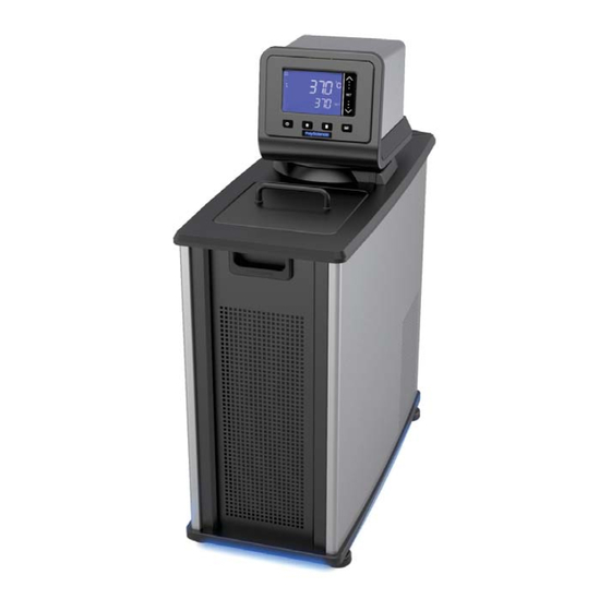
- Page 1 Circulating Baths with Standard Digital Temperature Controller Operator’s Manual Models: SD07R-20 SD7LR-20 SD15R-30 SD20R-30 SD28R-30 SD07H170 SD15H170 SD20H170 SD28H170 SD29VB3S SD29VB5R 110-512 PSC/EN 28 May 2014...
-
Page 2: Table Of Contents
Table of Contents Introduction ..............................3 PolyScience Circulating Baths with the Standard Digital Temperature Controller ........3 General Safety Information ........................4 Safety Recommendations......................... 5 Regulatory Compliance and Testing ......................6 Unpacking Your Circulator ........................6 Contents ..............................7 Controls and Components ........................8 Quick-Start .............................. - Page 3 Re-Installation ............................. 37 Troubleshooting Chart ..........................38 Technical Information ..........................40 Performance Specifications ........................40 Reservoir Fluids ............................41 Application Notes ............................ 42 Tubing and Fitting Temperature Ranges ....................43 Fluid Compatibility ..........................43 RS232 Communications ......................... 44 Equipment Disposal (WEEE Directive) ....................46 Replacement Parts and Accessories ......................
-
Page 4: Introduction
PolyScience Circulating Baths with the Standard Digital Temperature Controller Temperature Range Reservoir Model Type Capacity °C °F SD07R-20 Refrigerating / Heating Bath 7 liters -20° to 170°C -7° to 338°F SD7LR-20 Refrigerating / Heating Bath 7 liters -20° to 170°C -7°... -
Page 5: General Safety Information
General Safety Information When installed, operated, and maintained according to the directions in this manual and common safety procedures, your Circulating Bath should provide safe and reliable temperature control. Please ensure that all individuals involved in the installation, operation, or maintenance of this Circulating Bath read this manual thoroughly prior to working with the unit. -
Page 6: Safety Recommendations
Safety Recommendations To prevent injury to personnel and/or damage to property, always follow your workplace’s safety procedures when operating this equipment. You should also comply with the following safety recommendations: WARNING: ‡ This Circulating Bath is suitable only for use with Class I non-flammable fluids (per DIN 12876-1). ‡... -
Page 7: Regulatory Compliance And Testing
This equipment is compliant with the European Directive 2002/95/EC and its latest amendments on Restrictions on Hazardous Substances (RoHS) and below the given limits of hazardous substances. ETL Intertek (60 Hz units) UL 61010-1 / CSA C22.2 No. 61010-1 — Safety Requirements for Measurement, Control, and Laboratory Use;... -
Page 8: Contents
Contents The items included with your Circulator will vary depending on which model Circulating Bath you purchased. Refrigerating / Heating Heating Only Viscosity Bath Bath Bath Resource Disk with Operator’s Manual Reservoir Lid 3-ft / 0.91 m IEC to IEC Power Cord 6-ft / 1.82 m IEC to Mains Power Cord... -
Page 9: Controls And Components
Controls and Components Standard Digital Controller 3.75” Color LCD Display Touch Scroll Bar Power Key Set Key Home Key Menu Key Swivel 180 Latch Release Power Switch / Circuit Breaker Refrigeration Control (located on Refrigeration Connection (functional on Power Module on Refrigerating/Heating Refrigerating/Heating Circulators only) - Page 10 Refrigerating/Heating Baths Standard Digital Temperature Controller Reservoir Cover Reservoir Drain Valve and Port Drain Valve and Port (behind access panel) (right side on SD7LR-20) Side access on SD7LR-20) Washable Air Filter (behind access panel) IEC Power Connection to Refrigeration Control Refrigeration Power Module Connection Power...
- Page 11 Heating Only Baths Standard Digital Temperature Controller Reservoir Cover Reservoir Drain Valve and Port (behind access panel) Power Switch / Circuit Breaker IEC Power Connection to Mains Tap Water Cooling Connection Tap Water Cooling Connection (outlet) (inlet) 110-512 PSC/EN...
- Page 12 Viscosity Baths Standard Digital Controller Lidded Viscometer Ports Tap Water Cooling Coil Reservoir Drain Port WARNING: The top deck on Viscosity Baths is not attached. Do not remove deck while Circulator is operating. Do not lift bath by grasping the Temperature Controller or top deck. Always disconnect electrical power and drain fluid from bath before moving.
-
Page 13: Quick-Start
Quick-Start Unless otherwise specified, quick-start instructions apply to all models. See Installation and Startup for additional information. Maximum: 1 in. / 2.54 cm below underside of top deck Fill reservoir with fluid Minimum: 4.5 in. / 11.5 cm below top deck Heating only models Connect all electrical power cords Refrigerating / heating... - Page 14 Turn Controller “ON” Touch and hold or slide finger up/down Enter temperature scroll bar set point Press SET ¨ Set safety thermostat 110-512 PSC/EN...
-
Page 15: Installation And Startup
Installation and Startup Your Circulating Bath with Standard Digital Temperature Controller is designed to be simple to set-up and install. The only tools required are a flat-head screwdriver and a container for adding water or other suitable fluid to the bath reservoir. General Site Requirements Locate your Circulator on a level surface free from drafts and direct sunlight. -
Page 16: Pump Inlet And Outlet Connections
Pump Inlet and Outlet Connections WARNING: When connecting tubing to an external application, it is the user’s responsibility to make sure that the tubing and fittings connected to the Circulator are suitable for the fluid being used and the temperature range of operation. CAUTION: The Circulator’s bypass tubing is secured to the fluid inlet and outlet connections by high temperature nylon hose clamps, which can be removed by carefully cutting them with diagonal cutters. -
Page 17: Refrigeration Control Connections (Refrigerating/Heating Circulators Only)
Refrigeration Control Connections (Refrigerating/Heating Circulators only) Attach the Refrigeration Control Cable to the Refrigeration Control Connections on the rear of the Temperature Controller and the Refrigeration Power Module. Refrigeration Control Connection Refrigeration Control Cable Refrigeration Control Connection Electrical Power WARNING: The Circulator’s power cord must be connected to a properly grounded electrical receptacle. -
Page 18: Rs232 Serial Communication
NOTE: To conserve power when not in use, the LCD’s backlighting will go out about 5 seconds after “Standby” appears. The Power Key and PolyScience logo will remain lit to indicate that the Controller is energized and ready to use. IEC Power Connection to Refrigeration Power Module IEC to IEC Power Cord... -
Page 19: Controller Setup
Controller Setup Power Press . The Circulator will begin running, actual and set point temperatures will be displayed, and the word “SET” will be continuously lit. The circulating symbol will also be lit and the heating or refrigerating symbol may be lit or flashing. Heating Symbol Refrigerating Symbol... -
Page 20: Safety Set Temperature
Safety Set Temperature This is a “Do Not Exceed” temperature setting for your Circulator and is the temperature at which the heater will be turned OFF should the liquid level in the bath drop too low or the heater malfunctions. It is normally set about 5°... -
Page 21: Normal Operation
Normal Operation Keys and Controls Power Turns the Circulator’s Temperature Controller ON. Home Returns the LCD to the Main Operational Display (from any screen). Accesses the Temperature Controller’s set-up sub-menus. The items in these sub-menus are used to configure the Controller’s general Menu operational parameters (temperature unit, pump speed, upper and low temperature limits, etc. -
Page 22: Main Operational Display (Home)
Main Operational Display (Home) This is the Circulators main operational display. You can return to this screen at any time by pressing the key. Lit when heating Actual bath temperature Lit when refrigerating (Refrigerating/Heating models only) Set point temperature Lit when circulating bath fluid Set-Up Sub-Menus Pressing the... -
Page 23: Adjusting The Temperature Set Point
Adjusting the Temperature Set Point This is the temperature at which the fluid in your Circulating Bath will be maintained. It may be set to one- tenth of a degree over a range of -50.0° to +170.0°C / -60.0° to +340°F. The factory default set point is +20.0°C / +68.0°F. -
Page 24: Selecting The Temperature Unit
Selecting the Temperature Unit The temperature units sub-menu (°C / °F) allows you to select the temperature unit in which the actual bath temperature and set point temperature are displayed. The factory default is °C. Touch top arrow for degrees C Touch bottom arrow for degrees F To Access: Press the... -
Page 25: Selecting The Pump Speed
Selecting the Pump Speed This sub-menu allows you to select your Circulator’s pump speed. The choices are Low (LO) and High (HI); the factory default is High (HI). Touch top arrow to select High Touch bottom arrow to select To Access: Press the key until PUMP appears on the display. -
Page 26: Calibrating Your Circulator
Calibrating Your Circulator This sub-menu allows you to match the Circulator’s temperature display to an external reference thermometer. A value from -3.0° to +3.0°C may be entered; the factory default is 0.0°C. IMPORTANT: To prevent Offset Calibration value from being changed unintentionally, the following power down/power up sequence is required to enable the Calibration function. -
Page 27: Setting The Low Limit Temperature
Setting the Low Limit Temperature This sub-menu allows you to limit how low the temperature set point may be set. It also serves as a low limit safety, alerting you if bath temperature falls below the low limit temperature setting. The Low Limit value may be set from -52°... -
Page 28: Setting The High Limit Temperature
Setting the High Limit Temperature This sub-menu allows you to limit how high the temperature set point may be set. It also serves as a high limit safety, alerting you if bath temperature rises above the high limit temperature setting. The High Limit value may be set from +25°... -
Page 29: Selecting The Serial Communication Baud Rate
Selecting the Serial Communication Baud Rate This sub-menu allows you to select the speed at which your Circulator will transmit data. The setting on both the Circulator and the device it is connected to should match. The baud rate setting may be 1200, 2400, 4800, 9600, 19200;... -
Page 30: Setting The Auto Cool Temperature
Setting the Auto Cool Temperature This sub-menu is displayed only on Refrigerating / Heating Circulators. It determines the bath temperature at which refrigeration will be activated and permits more precise control when operating at high temperatures as well as more rapid cool downs. For most applications, an Auto Cool set point 15°C above room temperature is recommended. -
Page 31: Changing Your Circulator's Viewing Angle
Changing Your Circulator’s Viewing Angle Your Circulator is equipped with Swivel 180™, an innovative feature which permits viewing of the temperature display from anywhere over a 180° arc. There are positive stops at 45° intervals; however, the viewing angle may be set NOTE: anywhere within a 180°... -
Page 32: Inert Gas Purge
Inert Gas Purge A 0.125 in. / 3 mm port on the rear of the Temperature Controller is provided to allow you to blanket the surface of the liquid in the bath reservoir with nitrogen or another inert gas to help prevent condensation and dilution of the bath fluid. -
Page 33: Display Messages And Alarms
Display Messages and Alarms Message and/or Description Corrective Action Symbol Informational Message: Using the key, turn the Circulator OFF and then back ON. FAIL POWER Indicates that electrical power This will clear the message. was lost during operation. Warning: The temperature set Decrease the Low Limit temperature value or increase the point is below the Low Limit temperature set point. -
Page 34: Routine Maintenance And Troubleshooting
Routine Maintenance and Troubleshooting WARNING: Always turn your Circulator OFF and disconnect it from the electrical power outlet before performing any maintenance or service. WARNING: To avoid the potential for burns, allow the Circulator to cool completely before cleaning or performing any maintenance. WARNING: Always drain all fluid from the reservoir before moving or lifting your Circulator. -
Page 35: Checking The Over-Temperature Safety System
Checking the Over-Temperature Safety System Your Circulator incorporates over-temperature protection according to IEC 61010. For optimum safety, this system should be checked for proper operation at least every six months. This check must be performed with the unit running. 1. Press , enter a temperature set point of approximately 50°C, and then allow the bath to stabilize at that temperature. -
Page 36: Cleaning Your Circulator
Cleaning Your Circulator WARNING: It is the user’s responsibility to properly decontaminate the unit in the event hazardous materials are spilled on exterior or interior surfaces. Consult the manufacturer if there is any doubt regarding the compatibility of decontamination or cleaning agents. Temperature Controller Turn the Temperature Controller OFF by pressing and unplug power cord from the electrical outlet. -
Page 37: Temperature Controller Removal And Re-Installation
Temperature Controller Removal and Re-Installation Removal The Temperature Controller on your Circulating Bath is designed to be easily removed from the top deck without the use of special tools. It is removed as follows: 1. Place the tip of a small flat blade screwdriver under the retaining ring locking tab and pry up gently. -
Page 38: Re-Installation
Re-Installation The top deck of your Circulator incorporates four pins to facilitate positioning of the Temperature Controller when it is being reinstalled. These pins correspond to keyhole slots on the interior of the Circulator’s retaining ring. 1. With the retaining ring locking tab oriented above one of the indents on the top deck, slowly lower the Temperature Controller into the top deck opening until it is resting on top of the positioning pins. -
Page 39: Troubleshooting Chart
Troubleshooting Chart Problem Possible Causes Corrective Action Unit does not run No power to unit Check that the electrical cord is secure and (Digital Display is connected to an operating electrical outlet. blank) Unit does not run Unit in Standby mode Press Power Key on front panel. - Page 40 Problem Possible Causes Corrective Action Insufficient cooling Dust build up on air filter or Clean air filter and/or condenser as required. condenser Blocked air ventilation Remove blockages as required. screens Temperature set point is Decrease temperature set point. too high Excessive heat load Check that heat load does not exceed capacity of bath;...
-
Page 41: Technical Information
Model Type Capacity Range 60Hz Units 50Hz Units -20° to 170°C 120V, 60Hz, 240V, 50Hz, SD07R-20 Refrigerating / Heating Bath 7 liters -7° to 338°F -20° to 170°C 120V, 60Hz, 240V, 50Hz, SD7LR-20 Refrigerating / Heating Bath 7 liters -7° to 338°F -30°... -
Page 42: Reservoir Fluids
Reservoir Fluids Depending on your needs, a variety of fluids can be used with your Circulator. No matter what bath fluid is selected, it must be chemically compatible with the reservoir and the materials in your Circulator. It must also be suitable for the desired temperature range. WARNING: Do not use a flammable liquid as a bath fluid as a fire hazard may result. -
Page 43: Application Notes
WARNING: DO NOT USE THE FOLLOWING LIQUIDS: ‡ Automotive antifreeze with additives** ‡ Hard tap water** ‡ Deionized water with a specific resistance > 1 meg ohm ‡ Any flammable fluids ‡ Concentrations of acids or bases ‡ Solutions with halides: chlorides, fluorides, bromides, iodides or sulfur ‡... -
Page 44: Tubing And Fitting Temperature Ranges
Tubing and Fitting Temperature Ranges Material Temperature Range Buna N tubing -40° to 120°C ® Viton tubing -32° to 200°C ® Braided Teflon tubing -50° to 225°C Stainless steel fittings -45° to 225°C Nylon fittings -40° to 90°C Brass fittings -40°... -
Page 45: Rs232 Communications
RS232 Communications CAUTION: Always turn electrical power to the Circulator OFF before making a connection to the serial (DB9) port. Serial Connector — A DB9 connector is provided on the back panel of the Controller for RS232 data communication. RS232 Serial Communications Protocol —... - Page 46 Return Command Format Values Message Echo: i = 1 Set Command Echo SEi[CR] ![CR] No Echo: i = 0 Set Set Point SSiii.i[CR] i = any integer from 0-9 ![CR] On: i = 1 Set On Off SOi[CR] ![CR] Off: i = 0 Set High Alarm SHiii[CR] i = any integer from 0-9...
-
Page 47: Equipment Disposal (Weee Directive)
Equipment Disposal (WEEE Directive) This equipment is marked with the crossed out wheeled bin symbol to indicate it is covered by the Waste Electrical and Electronic Equipment (WEEE) Directive and is not to be disposed of as unsorted municipal waste. Any products marked with this symbol must be collected separately, according to the regulatory guidelines in your area. -
Page 48: Replacement Parts And Accessories
Replacement Parts and Accessories Part Description Number IEC to IEC Power Cord (Refrigerating/Heating Circulators) 120V, 60Hz 225-661 IEC to Mains Power Cord, U.S. plug type, 120V, 60Hz 225-473 (7 to 28 liter Refrigerating/Heating Circulators) IEC to Mains Power Cord, European plug type, 240V, 50Hz 225-346 (Refrigerating/Heating Circulators) IEC to Mains Power Cord, U.S. - Page 49 Digital to Analog Adapter, 10 mV 215-471 Reusable Air Filter for SD7LR-20 Refrigerating/Heating Circulator 305-057 Reusable Air Filter for SD07R-20 Refrigerating/Heating Circulator 305-054 Reusable Air Filter for SD15R-30 and SD20R-30 Refrigerating/Heating Circulators 305-055 O-Ring, Drain Valve (for Refrigerating/Heating and Heat only Circulators)
-
Page 50: Polyscience Circulating Bath Fluids
PolyScience Circulating Bath Fluids Circulating Bath Fluids Quantity Part Number polyclean Algaecide 8 oz / 236 ml 004-300040 polyclean Algaecide Twelve 8 oz / 236 ml bottles 004-300041 polyclean Bath Cleaner 8 oz / 236 ml 004-300050 polyclean Bath Cleaner Twelve 8 oz / 236 ml bottles 004-300051 polycool EG -25... -
Page 51: Warranty
Warranty The manufacturer agrees to correct for the original user of the product, either by repair (using new or refurbished parts), or at the manufacturer’s election, by replacement (with a new or refurbished product), any defects in material or workmanship which develop during the warranty period. The standard warranty is twenty-four (24) months after delivery of the product.
Need help?
Do you have a question about the SD07R-20 and is the answer not in the manual?
Questions and answers