Table of Contents
Advertisement
Quick Links
Advertisement
Table of Contents

Summary of Contents for Hydrophase Ridesteady
- Page 1 PRODUCTGUIDE...
-
Page 3: Table Of Contents
Table of Contents Package Contents ............................2 Overview ...............................4 Installation Guide Electrical Connection Diagram ....................5 Throttle Node / RPM Cable Install ..................6 Display / GPS Receiver Install ....................8 Temperature Sensor Install .......................9 Power Cable / CPU Install ......................10 CPU Power / Test ........................11 Operation Guide Overview ............................12 Usage Procedure ........................13... -
Page 4: Package Contents
Package Contents Package contents: items may appear slightly different than shown. Display / keypad GPS assembly PORT (or SNGL) Throttle Node STBD Throttle Node... - Page 5 Package Contents Power cable CPU-to-Node cable “Throttle” cable Tap connectors #6 wood screws RPM cable(s) Node-to-Node cable [Optional] Air temp sensor [Optional] Water temp sensor...
-
Page 6: Overview
If you have any questions or concerns regarding the instal- Timed-standby lation or use of your Ridesteady speed control system, just The industry-first timed-standby keeps the GPS active send us an e-mail or give us a call. We’re not satisfied until while reducing power when the ignition switch is OFF. -
Page 7: Electrical Connection Diagram
Electrical Connection Diagram Node-to-Node Cable To: Engine Wire To: Engine Wire Harness (CPS) Harness (CPS) -
Page 8: Throttle Node / Rpm Cable Install
VHF coax, or radios. These components may gener- Step 3 Connect the corresponding STBD or PORT throttle node to ate electrical interference that could interfere with the Ridesteady the APS, ensuring that the connector latch is engaged. Connect the system. - Page 9 Throttle Node / RPM Cable Install 3) Complete connections; mount throttle nodes Step 2 While pulling the inner connector latch outward, gently pull back on the CPS connector housing to disconnect it from the wiring harness. It may require a little “wiggling” to free. Step 1 Route the node-to-node cable (for twin-engine boats) from the STARBOARD to PORT throttle node, routing away from the en- gines.
-
Page 10: Display / Gps Receiver Install
CPU mounted in the coming steps. Step 2 Install the in-dash display. 1. Remove the nuts and back clamp from the rear of the Ridesteady display. 2. Insert the display into the hole in the dash. From behind the dash, reinstall the back clamp and nuts. -
Page 11: Temperature Sensor Install
Temperature Sensor Install 6) Mount [optional] temperature sensors to insert the contacts of the connector into the housing. Refer to the pictures below for more information. 1. Locate the arrow on the top of the connector 2. Position the WHITE wire contact just inside the right-most con- nector slot, denoted by the arrow. -
Page 12: Power Cable / Cpu Install
Alternatively, the +12V wire on any light that comes ON when the navigation lights are turned ON may be tapped. The green Ridesteady LIGHTS wire automatically dims the dis- play and is not necessary for any other operations. It may simply be taped off with electrical tape if desired. -
Page 13: Cpu Power / Test
2. Turn an engine ignition key to the “ON” position (without start- ing the engine). The blue LED on the CPU should light up and the display should turn on, showing the Ridesteady logo and then the main screen. 3. For twin engines, turn the key in the previous step OFF and turn ON the opposing engine key (without starting). -
Page 14: Overview
Operation Guide: Overview Display overview The Ridesteady speed control system uses a 2 button with WARNING rotary / push knob control panel with backlit graphical LCD The Ridesteady speed control system was designed from display. the ground up to be the easiest-to-use speed control sys- tem available. -
Page 15: Usage Procedure
APS. This “extra throttle signal” can cause the set speed by too much (this may be detected as a brief a bigger overshoot on bring up, as Ridesteady has more reduction in speed). It will then regulate the throttle to throttle that it must reduce in order to hit the set speed. -
Page 16: Main Screen
Operation Guide: Main Screen Overview... - Page 17 (RPM). With twin-en- gine applications, the “sync mstr” setting determines which engine’s speed will be shown. Note that needle-based tachometers often have some inaccuracies, so it may not match perfectly with the RPM speed Ridesteady reports.
-
Page 18: Standby Screen
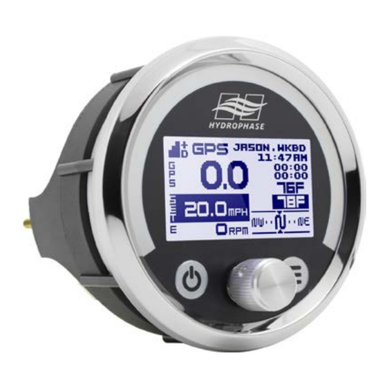
Operation Guide: Standby Screen GPS Status Indicator: • continues to track satellites GPS Time: • # bars: signal precision estimation • GPS-synchonized time • top #: number of satellites tracking • Large font for easy boat-wide viewing “+” indicates 10 or more satellites •... -
Page 19: Settings Menu
Operation Guide: SETTINGS Menu Press & hold settings SETTINGS menu 2 seconds when ridestats Follow the guide below to customize the Ridesteady speed < 5 MPH user: 1 speed control system to your preference. Often the / 8 KPH name: guest.01 default settings provide the best result and require no adjustments. - Page 20 TANT: Reducing the volume to low levels (such as below 10%) may prevent beeping at all. 0% will turn OFF the As “response” is increased, the Ridesteady speed control beeper completely. Warning beeps will not be heard! becomes more aggressive in how it maintains the set speed.
- Page 21 Operation Guide: SETTINGS Menu resetting the Ridestats for the day. either the GPS or paddlewheel speed to be displayed when in PW control mode. pwr off delay: 30 min Adjust the time after the ignition key is switched OFF (and the system active beep: yes Set whether the system enters “timed-standby”) before the power is killed.
- Page 22 20 20 Operation Guide: SETTINGS Menu factory reset Reset Ridestats, users, system set- tings, or everything back to factory defaults. Rotate the knob to select the user which will have its stats or settings reset, or move the cursor to select the reset to be per- formed.
-
Page 23: Wire Tapping & Troubleshooting
Avoid “bundling” the throttle motor power cable with any other wire other than the power cable. 2. Insert the Ridesteady wire fully into the “back” of the tap connector. A stop will prevent the wire from coming out Issue: LCD slow to respond the other side. -
Page 24: Purchase Agreement
Purchase of Product. Hydrophase agrees to sell to You, and You agree to buy from Hydrophase, the product or products (collectively, the “Prod- uct”) listed on the separate order form, and in the quantities and at the purchase price listed thereon. Upon Hydrophase’s receipt of Your payment in full and Your agreement to the terms and conditions of this Agreement, Hydrophase shall cause the Product to be delivered to You at the shipping address specified by You. -
Page 25: Limited Warranty
HYDROPHASE, LLC, a Texas limited liability company (“Hydrophase”), makes the following Limited Warranty with respect to the product(s) manufactured and sold by Hydrophase (collectively, the “Product”). Hydrophase warrants the Product to be free from defects in workmanship and materials for a period of one (1) year after the date of purchase.
Need help?
Do you have a question about the Ridesteady and is the answer not in the manual?
Questions and answers