Table of Contents
Advertisement
Model 77722-00
(US & Canada only) Toll Free 1-800-MASTERFLEX • 1-800-637-3739
(Outside US & Canada) 1-847-549-7600 • 1-847-381-7050
E-mail: techinfo@coleparmer.com
www.masterflex.com • www.coleparmer.com
OPERATING MANUAL:
FH100 PRECISION
VARIABLE-SPEED
PERISTALTIC PUMP
SYSTEM
Model Nos.
77722-00
77722-02
A-1299-7292
Edition 01
Advertisement
Table of Contents

Summary of Contents for Catalyst 77722-00
- Page 1 OPERATING MANUAL: FH100 PRECISION VARIABLE-SPEED PERISTALTIC PUMP SYSTEM Model Nos. 77722-00 77722-02 Model 77722-00 A-1299-7292 Edition 01 (US & Canada only) Toll Free 1-800-MASTERFLEX • 1-800-637-3739 (Outside US & Canada) 1-847-549-7600 • 1-847-381-7050 E-mail: techinfo@coleparmer.com www.masterflex.com • www.coleparmer.com...
- Page 2 Preface Preface © 2014 Cole-Parmer Instrument Company LLC. All rights reserved. NORPRENE, PHARMED and TYGON – Reg TM Saint-Gobain Performance Plastics Corp. Trademarks bearing the symbol in this publication are registered in the U.S. and in other countries. ® A-1299-7292 19714 2014-10-29 First Edition...
- Page 3 Preface Safety Precautions SAFETY DANGER: Remove power from the pump before any cleaning operation is started. PRECAUTIONS WARNING: Remove power from the pump before attempting any maintenance. WARNINGS: Tubing breakage may result in fluid being sprayed from pump. Use appropriate measures to protect operator and equipment.
- Page 4 Preface Safety 1. Read instructions before operating the unit. 2. Observe safety precautions at all times, especially when pumping dangerous liquids. Always have the clear plastic cover properly mounted on the Pump Head and, in general, protect the pump area from accidental spillage of liquid.
-
Page 5: Table Of Contents
Table of Contents Page Section 1 INTRODUCTION ..........1-1 General Description . - Page 7 Figures Figures Page Controls, Indicators and Connectors ....... .1-2 Tube Loading Upper Retainer ........3-1 Tube Loading Lower Retainer .
-
Page 9: Introduction
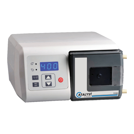
Introduction Section 1 General Description The FH100 Precision Variable-Speed Peristaltic Pump System provides continuous pumping of fluids while power is supplied. These Pump Systems are ETL and CE certified. The pump speed range for both models is 4-400 rpm. Cole-Parmer FH100 Precision Variable-Speed Peristaltic Pump System Operating Manual... -
Page 10: Controls, Indicators And Connectors
Section 1 Introduction Controls, Indicators and Connectors Front View Rear View Figure 1-1. Controls, Indicators and Connectors A. POWER (ON/OFF) SWITCH: Turns the unit ON or OFF. B. SPEED KEYS: Sets the speed of the pump. The higher the number, the faster the speed of the pump. -
Page 11: Installation And Setup
When tubing links are used, best performance will be achieved when input and output tubing connected to the link are the same ID as the link. 77722-00 Pump Systems accept tubing ID sizes of 0.8 mm to 8.0 mm (1/32 in to 5/16 in ) by 1.6 mm (1/16 in) wall. -
Page 13: Operation
Operation Section 3 Inserting Tubing WARNINGS: Tubing breakage may result in fluid being sprayed from pump. Use appropriate measures to protect operator and equipment. Turn Pump System off before removing or installing tubing. Fingers or loose clothing could be caught in the pump mechanism. -
Page 14: Tubing Inspection And Replacement
Section 3 Operation Inserting Tubing 5. Install the tubing around the rotor, going with the natural curve or lay of the tubing and center the tubing on the rollers. (continued) 6. Open the lower retainer by using just one finger to open the retainer and insert the tube and release the retainer. -
Page 15: External Operation
Section 3 Operation External Operation Models are equipped with inputs that can be controlled by external signals connected at the rear panel 9-pin “D” shell connector. The External inputs permit control of the pump by remote equipment or accessories. Figure 3-3 shows the signal locations of the connector. -
Page 16: External Inputs
Section 3 Operation External Inputs The FRONT INT/EXT key enables external functions. Switching to INT on the display disables the external functions, allowing the front panel controls to operate the pump. When the INT/EXT key is in the EXT position, starting and stopping the pump is controlled by an external contact closure between pins 6 and 7 (Jumper B), and the pump speed is determined by an externally supplied 0–10V or 4–20 mA source. -
Page 17: Maintenance
Maintenance Section 4 WARNING: Remove power from the pump before attempting any maintenance. The speed control circuit has solid-state components that do not require service. An excessive load on the system may, however, cause the fuse to blow. An indication of an excessive load is a switch that does not light with power applied to the pump and when the ON-OFF switch is in the ON position. -
Page 19: Troubleshooting
Troubleshooting Section 5 Troubleshooting Chart Symptom Remedy Unit will not turn on Verify that the unit is plugged into a functioning outlet. Verify that the power cord is firmly attached to the unit. Verify that the fuse for the incoming voltage is not blown (located in the slot next to the power cord). -
Page 21: Replacement Parts And Accessories
Description Part Number Qty. Rubber Foot (pkg. of 6) A-1390-0004-CR Fuse (T3.15A, 250V, 5 x 20 mm) 77500-25 Pump Replacement (for model 77722-00) 112616-CR Pump Replacement (for model 77722-02) 112617-CR Ferrite, Line Cord Snap-on, (CE Required) B-3689-CR Line Cord, Australia... -
Page 23: Specifications
Specifications Section 7 Output: Speed: 4 - 400 rpm Torque: 168 in-oz (12.1 kg•cm) Input: Operating Voltage/Frequency: 90-260Vrms, 50/60 Hz, 1.6A @ 115Vrms, 1.9A @ 230 Vrms External Inputs: START/STOP, CW/CCW, Contact closure Remote/Local Speed Control Voltage input 0–10V DC @ 10 kohm, Accuracy: ±0.5% Full Scale Current input... -
Page 25: Warranty
Warranty, Product Return and Section 8 Technical Assistance Warranty This product is warranted against defects in material or workmanship, and at the option of the manufacturer or distributor, any defective product will be repaired or replaced at no charge, or the purchase price will be refunded to the purchaser, provided that: (a) the warranty claim is made in writing within the period of time specified on the warranty card, (b) proof of purchase by bill of sale or receipted invoice is submitted concurrently with... -
Page 26: Product Return
Section 8 Warranty, Product Return and Technical Assistance Product Return To limit charges and delays, contact the seller or Manufacturer for authorization and shipping instructions before returning the product, either within or outside of the warranty period. When returning the product, please state the reason for the return. - Page 28 (US & Canada only) Toll Free 1-800-MASTERFLEX • 1-800-637-3739 (Outside US & Canada) 1-847-549-7600 • 1-847-381-7050 www.masterflex.com • www.coleparmer.com E-mail: techinfo@coleparmer.com *EN809 manufactured by: Cole-Parmer Instrument Company LLC 28W092 Commercial Avenue Barrington, IL 60010 Printed in U.S.A.
Need help?
Do you have a question about the 77722-00 and is the answer not in the manual?
Questions and answers