Table of Contents
Advertisement
Advertisement
Table of Contents
Troubleshooting

Summary of Contents for Strider SE2-MC2U-C1-T
- Page 1 ® SE2 Series Industrial Ethernet Switches USER MANUAL Manual Number: SE2-USER-M...
- Page 3 ~ WARNING ~ Thank you for purchasing automation equipment from Automationdirect.com ® , doing business as, AutomationDirect. We want your new automation equipment to operate safely. Anyone who installs or uses this equipment should read this publication (and any other relevant publications) before installing or operating the equipment.
- Page 4 ~ ADVERTENCIA ~ Gracias por comprar equipo de automatización de Automationdirect.com ® . Deseamos que su nuevo equipo de automatización opere de manera segura. Cualquier persona que instale o use este equipo debe leer esta publicación (y cualquier otra publicación pertinente) antes de instalar u operar el equipo. Para reducir al mínimo el riesgo debido a problemas de seguridad, debe seguir todos los códigos de seguridad locales o nacionales aplicables que regulan la instalación y operación de su equipo.
- Page 5 ~ AVERTISSEMENT ~ ® Nous vous remercions d’avoir acheté l’équipement d’automatisation de Automationdirect.com , en faisant des affaires comme, AutomationDirect. Nous tenons à ce que votre nouvel équipement d’automatisation fonctionne en toute sécurité. Toute personne qui installe ou utilise cet équipement doit lire la présente publication (et toutes les autres publications pertinentes) avant de l’installer ou de l’utiliser.
-
Page 7: User Manual
® SE2 Series Industrial Ethernet Switches USER MANUAL Please include the Manual Number and the Manual Issue, both shown below, when communicating with Technical Support regarding this publication. Manual Number: SE2-USER-M Issue: 2nd Edition, Revision A Issue Date: 08/17 Publication History Issue Date Description of Changes... -
Page 9: Table Of Contents
able of onTenTs Chapter 1: Hardware Introduction ����������������������������������������������������������������������������������������������������������������� 1-2 Conventions Used �������������������������������������������������������������������������������������������������������� 1-2 General Information ���������������������������������������������������������������������������������������������������� 1-3 Product Overview Stride SE2 Unmanaged Models ���������������������������������������������������� 1-5 Product Overview Stride SE2 PoE Unmanaged Models ��������������������������������������������� 1-6 Product Overview Stride SE2 Managed Models ��������������������������������������������������������� 1-7 Switch Accessories �������������������������������������������������������������������������������������������������������... - Page 10 Table of Contents Chapter 2: Managed Switch Introduction Connecting to the Switch the First Time ��������������������������������������������������������������������2-2 Why Do You Need a Managed Switch? ��������������������������������������������������������������������2-10 Enhanced Traffic Filtering �����������������������������������������������������������������������������������������2-10 Troubleshooting �������������������������������������������������������������������������������������������������������2-11 Redundancy �������������������������������������������������������������������������������������������������������������2-11 Security ��������������������������������������������������������������������������������������������������������������������2-12 Better Network Awareness ����������������������������������������������������������������������������������������2-12 Chapter 3: Managed Switch Basic Features Managed Switch Features �������������������������������������������������������������������������������������������3-2 Switch Management Settings �������������������������������������������������������������������������������������3-3 Port Configuration������������������������������������������������������������������������������������������������������3-4...
- Page 11 Table of Contents Chapter 4: Advanced Network Behavior Features Traffic Priority (Priority Queuing QoS, Quality of Service) ��������������������������������������� 4-2 802�1p Example ������������������������������������������������������������������������������������������������������� 4-4 Port Trunk – Link Aggregation ����������������������������������������������������������������������������������� 4-7 Port Rate �������������������������������������������������������������������������������������������������������������������� 4-9 AD-Ring �������������������������������������������������������������������������������������������������������������������� 4-10 Concepts ����������������������������������������������������������������������������������������������������������������� 4-10 Implementation of AD-Ring ������������������������������������������������������������������������������������...
- Page 12 Table of Contents Syslog ������������������������������������������������������������������������������������������������������������������������ 5-13 SNMP ������������������������������������������������������������������������������������������������������������������������ 5-14 Implementation ������������������������������������������������������������������������������������������������������� 5-14 Explanation ������������������������������������������������������������������������������������������������������������� 5-14 MIB Introduction ����������������������������������������������������������������������������������������������������� 5-15 SNMPv3��������������������������������������������������������������������������������������������������������������������� 5-16 Introduction ������������������������������������������������������������������������������������������������������������ 5-16 Implementation ������������������������������������������������������������������������������������������������������� 5-16 Modbus TCP ������������������������������������������������������������������������������������������������������������� 5-17 EtherNet/IP ��������������������������������������������������������������������������������������������������������������� 5-18 Firmware Update ������������������������������������������������������������������������������������������������������ 5-18 Configuration Upload and Download ��������������������������������������������������������������������� 5-19 Load Default �������������������������������������������������������������������������������������������������������������...
- Page 13 Table of Contents Troubleshooting AD-Ring ������������������������������������������������������������������������������������������� D-4 Troubleshooting VLANs ���������������������������������������������������������������������������������������������� D-7 Installing Switch Firmware ����������������������������������������������������������������������������������������� D-8 Appendix E: Ethernet IP EtherNet/IP Switch Management ������������������������������������������������������������������������������� E-2 Implicit (I/O) Messaging ��������������������������������������������������������������������������������������������� E-3 Explicit Messaging ������������������������������������������������������������������������������������������������������� E-6 Appendix F: Modbus TCP MODBUS TCP Definition ��������������������������������������������������������������������������������������������� F-2 Port Definition ������������������������������������������������������������������������������������������������������������...
- Page 15 hapter hapter hapter ardware In this Chapter... Introduction ........................1-2 Conventions Used ......................1-2 General Information ......................1-3 Product Overview Stride SE2 Unmanaged Models ............1-5 Product Overview Stride SE2 PoE Unmanaged Models ..........1-6 Product Overview Stride SE2 Managed Models ............1-7 Switch Accessories ......................1-8 SFP Fiber Transceivers ���������������������������������������������������������������������������������������������������1-8 Mounting Brackets �������������������������������������������������������������������������������������������������������1-9 DIP Switch (Unmanaged DIN rail mounted switches) ..........1-10...
-
Page 16: Chapter 1: Hardware
® Chapter 1: Hardware Introduction The Purpose of this User’s Manual ® Thank you for purchasing our Stride SE2 series Industrial Ethernet Switches. This manual describes AutomationDirect.com’s Stride industrial Ethernet switches, their specifications, included components, and provides you with important information for installation, connectivity and setup. -
Page 17: General Information
Chapter 1: Hardware General Information Overview This user’s manual will help you install and maintain the Stride industrial Ethernet switches. Installation of these devices is very easy and they will begin to operate as soon as they are powered up. Operation Unlike an Ethernet hub that broadcasts all messages out all ports, these industrial Ethernet switches will intelligently route Ethernet messages only out the appropriate port. -
Page 18: Fcc Statement
® Chapter 1: Hardware Installation and Hazardous Area Warnings WARNING: These products should not be used to replace proper safety interlocking. No software-based device (or any other solid-state device) should ever be designed to be responsible for the maintenance of consequential equipment or personnel safety. In particular, AutomationDirect.com disclaims any responsibility for damages, either direct or consequential, that result from the use of this equipment in any application. -
Page 19: Product Overview Stride Se2 Unmanaged Models
Stride SE2 Unmanaged Models Number of Ports Input power Part Number Operating Temp Agency Approvals RJ45 RJ45 (max.) Fiber 10/100 10/100 SE2-MC2U-C1-T – – 1 SC -40 to +75°C (-40 to +167°F) SE2-MC2U-T1-T – – 1 ST 3.4 W -10 to +60 °C SE2-SW5U –... -
Page 20: Product Overview Stride Se2 Poe Unmanaged Models
® Chapter 1: Hardware Product Overview Stride SE2 PoE Unmanaged Models Stride SE2 Unmanaged PoE Models Number of Ports RJ45 Part Number Operating Temp Agency Approvals RJ45 RJ45 RJ45 10/100 10/100 GbE PoE UL/cUL 61010-1 and 61010-2-201 SE2-SWP5U-T – – -40 to +75°C Class 1, Div. -
Page 21: Product Overview Stride Se2 Managed Models
Chapter 1: Hardware Product Overview Stride SE2 Managed Models Stride SE2 Series Managed Models Input Power Part Number Ethernet Ports Fiber Ports Operating Temp Agency Approvals (max) SE2-SW8M – 8.1 W 2 GbE SE2-SW8M-2P 9.1 W SFP* UL/cUL 508, SE2-SW8M-2C1 2 SC -40 to +75°C Class 1, Div. -
Page 22: Switch Accessories
® Chapter 1: Hardware Switch Accessories SFP Fiber Transceivers Stride SFP (small form-factor pluggable) transceivers, also called mini-GBIC, are compact, hot-swappable transceivers with LC fiber connectors. Models SE2-SW8M-2P, SE2SW18MG-2P, and SE2-SW10UG-2P-T have ports that accept these optional transceivers to add fiber connectivity at Fast Ethernet or Gigabit Ethernet speed. NOTE: SE2-SW10UG-2P-T will only accept Gigbit speed SFPs. -
Page 23: Mounting Brackets
Chapter 1: Hardware Mounting Brackets SE2-PM1 and SE2-PM3 panel mounting brackets allow DIN rail mount models of Stride SE2 series Ethernet switches to be mounted to a panel or an appropriate flat surface. • SE2-PM1 is compatible with SE2-SW5Ux, SE2-SW8U-x, and SE2-MCx •... -
Page 24: Dip Switch (Unmanaged Din Rail Mounted Switches)
® Chapter 1: Hardware DIP Switch (Unmanaged DIN rail mounted switches) DIP switch I enables the broadcast storm protection feature on the unmanaged DIN rail mounted switches. A broadcast storm is usually caused by a loop in the network and results in network traffic interruption. -
Page 25: Reset (Managed Switches)
Chapter 1: Hardware Reset (Managed Switches) The switch can be reset (power cycle) by pressing the RESET button on the face of the switch for 1-3 seconds. The switch will be RESET to FACTORY DEFAULT by pressing the RESET button on the face of the switch for 5 seconds. -
Page 26: Led Indicators
® Chapter 1: Hardware LED Indicators LEDs on DIN rail Mounted Models Power LEDs Communication LEDs Indicates that there is a proper Ethernet connection (Link) between the port and another Ethernet device, but no communications activity is detected. Indicates that there is a proper Ethernet connection (Link) ACT/LNK LED Blinking between the port and another Ethernet device, and that there is... - Page 27 Chapter 1: Hardware LEDs on IP65 Models Power LEDs Ethernet LEDs (one per M12 connection) IP65 Models Front Panel LEDs Power 1 connected and operational Power 1 LED Power 1 no voltage Power 2 connected and operational Power 2 LED Power 2 no voltage Ethernet port connected Ethernet port...
-
Page 28: Installation, Din Rail Mounting
® Chapter 1: Hardware Installation, DIN Rail Mounting Stride SE2 series switches can be snapped onto a standard 35 mm x 7.5 mm height DIN rail (Standard: CENELEC EN50022) and can be mounted either vertically or horizontally. See Installation, IP65 Switches Panel Mounting later in this chapter for mounting IP65 rated switches. - Page 29 Chapter 1: Hardware DIN rail removal steps (Unmanaged Models): Lift unit up Rotate body to remove from of unit. DIN rail. DIN ra Insert screwdriver into spring locking plate and rotate upward to release DIN rail clamp. 1-15 Stride SE2 Series Industrial Ethernet Switches User Manual 2nd Ed.
-
Page 30: Installation, Optional Panel Mounting
® Chapter 1: Hardware Installation, Optional Panel Mounting Stride SE2 Din rail series switches can be panel mounted with the addition of the optional panel mounting brackets SE2-PM1 or SE2-PM3. • SE2-PM1 is compatible with SSE2-SW5Ux, SE2-SW8U-x, and SE2-MCx • SE2-PM3 is compatible with SE2-SWPx, SE2-SW8UG-T, SE2-SW10UG-2P-T, SE2-SW16U-T and all SE2 managed switches. -
Page 31: Installation, Ip65 Switches Panel Mounting
Chapter 1: Hardware Installation, IP65 Switches Panel Mounting IP65 rated switches are designed to be panel mounted vertically or horizontally using the steps below. Panel mounting steps: • Use the dimensional drawing to locate (4) mounting screws on the panel. Recommended screws are #4-40 pan head. -
Page 32: Dimensional Drawings
® Chapter 1: Hardware Dimensional Drawings NOTE: Allow 20mm (0.79 in) clearance around each switch for proper cooling. Dimensions mm / [inches] SE2-MC2U-C1-T, SE2-MC2U-T1-T, SE2-SW5U, SE2-SW5U-T, SE2-SW5UG-T, SE2-SW8U SE2-SW5U-1C1-T, SE2-SW5U-1T1-T SE2-SW8U-T SE2-SW8U-2C1-T SE2-SW8U-2T1-T 1-18 Stride ® SE2 Series Industrial Ethernet Switches User Manual... - Page 33 Chapter 1: Hardware Dimensional Drawings (cont’d) NOTE: Allow 20mm (0.79”) clearance around each switch for proper cooling. Dimensions mm / [inches] SE2-SW10UG-2P-T SE2-SW8UG-T SE2-SW16U-T 1-19 Stride SE2 Series Industrial Ethernet Switches User Manual 2nd Ed. Rev. A ®...
- Page 34 ® Chapter 1: Hardware Dimensional Drawings (cont’d) NOTE: Allow 20mm (0.79”) clearance around each switch for proper cooling. Dimensions mm / [inches] SE2-SWP5U-T SE2-SWP5UG-T 1-20 Stride ® SE2 Series Industrial Ethernet Switches User Manual 2nd Ed. Rev. A...
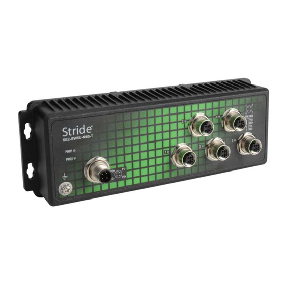
- Page 35 Chapter 1: Hardware Dimensional Drawings (cont’d) Dimensions mm / [inches] SE2-SW5U-N65-T SE2-SW8U-N65-T 1-21 Stride SE2 Series Industrial Ethernet Switches User Manual 2nd Ed. Rev. A ®...
- Page 36 ® Chapter 1: Hardware Dimensional Drawings (cont’d) Dimensions mm / [inches] SE2-SW8M SE2-SW8M-2P 1-22 Stride ® SE2 Series Industrial Ethernet Switches User Manual 2nd Ed. Rev. A...
- Page 37 Chapter 1: Hardware Dimensional Drawings (cont’d) Dimensions mm / [inches] SE2-SW8M-2C1 SE2-SW8M-2T1 1-23 Stride SE2 Series Industrial Ethernet Switches User Manual 2nd Ed. Rev. A ®...
- Page 38 ® Chapter 1: Hardware Dimensional Drawings (cont’d) Dimensions mm / [inches] SE2-SW16M SE2-SW18MG-2P 1-24 Stride ® SE2 Series Industrial Ethernet Switches User Manual 2nd Ed. Rev. A...
- Page 39 Chapter 1: Hardware Dimensional Drawings (cont’d) Dimensions for SFP Transceiver Modules Dimensions mm / [inches] SFP-4K-FMF, SFP-30K-FSF, SFP-500-GMF, SFP-2K-GMF, SFP-10K-GSF and SFP-30K-GSF 1-25 Stride SE2 Series Industrial Ethernet Switches User Manual 2nd Ed. Rev. A ®...
-
Page 40: Power Wiring
® Chapter 1: Hardware Power Wiring WARNING: Before performing any wiring to these switches make sure... • The area is currently nonhazardous (especially when working in Class 1, Div 2 or Zone 2 hazardous locations). • Power is off to the switch •... - Page 41 Chapter 1: Hardware Unmanaged PoE Switches NOTE: In order to source power (PSE), a PoE switch must be supplied with 48-58 VDC. When supplied with 12-24 VDC, the switch will communicate properly via Ethernet but will not source power by PoE to a connected device (PD). The switch can be powered from the same source that is used to power your other devices.
- Page 42 ® Chapter 1: Hardware M12 Connector Equipped Models The switch can be powered from the same source that is used to power your other devices. To maintain the UL listing, this must be a Class 2 power supply. 12, 24 or 48 VDC or 24VAC needs to be applied through an M12 (A coded, female, 4-pin) connector as shown in the chart below.
-
Page 43: Communication Ports Wiring
Chapter 1: Hardware Managed Switches The switch can be powered from the same DC source that is used to power your other devices. To maintain the UL listing, this must be a Class 2 power supply. A DC voltage in the range of 12 to 24 VDC needs to be applied between the P1+ terminal and the P1- terminal as shown below. -
Page 44: Ethernet Cable Wiring
® Chapter 1: Hardware Ethernet Cable Wiring Straight-thru Cable Wiring Cross-over Cable Wiring Pin 1 Pin 1 Pin 1 Pin 3 Pin 2 Pin 2 Pin 2 Pin 6 Pin 3 Pin 3 Pin 3 Pin 1 Pin 4 Pin 4 Pin 4 Pin 4 Pin 5... - Page 45 Chapter 1: Hardware Verifying Connectivity After all Ethernet and/or fiber connections are made, check the LEDs corresponding to the ports that each of the devices are connected to. Ensure that for each port that is in use, the LED is on or blinking. If a port LED is off, go back and check for connectivity problems between that port and the network device connected to that port (see prior section on LEDs).
-
Page 46: Technical Specifications
® Chapter 1: Hardware Technical Specifications Unmanaged Models The following specifications refer to these models. SE2-MC2U-C1-T SE2-SW5U SE2-SW8U SE2-SW10UG-2P-T SE2-MC2U-T1-T SE2-SW5U-T SE2-SW8U-T SE2-SW16U-T SE2-SW5UG-T SE2-SW8U-2C1-T SE2-SW5U-1C1-T SE2-SW8U-2T1-T SE2-SW5U-1T1-T SE2-SW8UG-T General Specifications Operating Mode Store and forward wire speed switching, non-blocking Devices Supported All IEEE 802.3 compliant devices are supported... - Page 47 Chapter 1: Hardware Unmanaged Models Technical Specifications (cont’d) RJ45 Ports Port Type Shielded RJ45 IEEE 802.3i, 802.3u, 802.3x for 10/100 Ethernet Ethernet Compliance IEEE 802.3ab, 802.3z for Gigabit Ethernet Auto-Crossover Yes, allows you to use straight-through or crossover wired cables Auto-Sensing Operation Yes, full and half duplex Auto-Negotiating Speed...
-
Page 48: Unmanaged Poe Models
® Chapter 1: Hardware Unmanaged PoE Models The following specifications refer to these models. SE2-SWP5U-T SE2-SWP5UG-T General Specifications Operating Mode Store and forward wire speed switching, non-blocking Devices Supported All IEEE 802.3 compliant devices are supported MAC Addresses Packet Buffer 1Mbit Packet Forwarding Rate 1.5 Mpps... - Page 49 Chapter 1: Hardware Unmanaged PoE Models Technical Specifications (cont’d) Power Details Redundant Input Terminals Power Input Class 2 Power Supply 12 or 24VDC for Ethernet communications only, 48-58 VDC for PoE (15.4 W per port) Input Voltage 54-58 VDC for PoE+ (30W per port) Reverse Power Protection 24-16 AWG, max wire length 3m (9.84 ft);...
-
Page 50: Unmanaged Ip65 Rated Models
® Chapter 1: Hardware Unmanaged IP65 Rated Models The following specifications refer to these models. SE-SW5U-N65-T SE-SW8U-N65-T General Specifications Operating Mode Store and forward wire speed switching, non-blocking Devices Supported All IEEE 802.3 compliant devices are supported MAC Addresses Packet Buffer 1Mbit Packet Forwarding Rate 1.2 Mpps... - Page 51 Chapter 1: Hardware Unmanaged IP65 Rated Models (cont’d) M12 Ethernet Ports 10/100BaseT ports M12, female, D-coding, 4-pin Ethernet Compliance IEEE 802.3i, 802.3u, 802.3x Yes, allows you to use straight-through or Auto-Crossover crossover wired cables Auto-Sensing Operation Yes, full and half duplex Auto-Negotiating Speed Flow Control Automatic...
-
Page 52: Managed Models
® Chapter 1: Hardware Managed Models The following specifications refer to these models. SE2-SW8M SE2-SW16M SE2-SW18MG-2P SE2-SW8M-2C1 SE2-SW8M-2T1 SE2-SW8M-2P General Specifications Operating Mode Store and forward wire speed switching, non-blocking Devices Supported All IEEE 802.3 compliant devices are supported MAC Addresses 16K for SE2-SW8M-2P SNMP v1 / v2 / v3, RMON, DHCP, SNTP, TFTP, STP, RSTP, QoS / DS, IGMPv1 / v2, Ethernet Protocols... - Page 53 Chapter 1: Hardware Managed Models (cont’d) Power Details Power Input Redundant Input Terminals Input Voltage Class 2 Power Supply: 12-24 VDC Reverse Power Protection 18-12 AWG, max wire length 3m (9.84 ft); Wire Size and Torque Wire strip length 7mm; Torque: 3.5 lb·in (0.4 N·m) Power Consumption Refer to Models table on previous pages in this chapter...
- Page 55 hapter hapter hapter anaged witch ntroduction In this Chapter... Connecting to the Switch the First Time ..............2-2 Why Do You Need a Managed Switch? ..............2-10 Enhanced Traffic Filtering ..................2-10 Troubleshooting ..................... 2-11 Redundancy ......................2-11 Security ........................2-12 Better Network Awareness ..................
-
Page 56: Connecting To The Switch The First Time
Chapter 2 - Getting Started Connecting to the Switch the First Time The SE2 series managed switches may be managed via a mini-USB console port using CLI, or via Ethernet port using CLI, telnet or web browser. Information on console port access is provided in Appendix C. Connecting to the switch for the first time over Ethernet is the recommended means of initial access. - Page 57 Chapter 2 - Getting Started This example shows a switch connected directly to a PC running Windows 8.1. 1. Open Network and Sharing Center: 2a. Click on the name of the NIC connected to the switch to open the NIC status window. 2b.
- Page 58 Chapter 2 - Getting Started 3a. Click to highlight Internet Protocol Version 4 (TCP/IPv4). 3b. Click the Properties button. Stride ® SE2 Series Industrial Ethernet Switches User Manual 2nd Ed. Rev. A...
- Page 59 Chapter 2 - Getting Started Write down (or screen capture) the existing settings so you can revert to them after we change the switch IP address. For our example, the PC starting IP address is 10.11.47.123, the subnet mask is 255.255.255.0 and there is no default gateway. Stride SE2 Series Industrial Ethernet Switches User Manual 2nd Ed.
- Page 60 Chapter 2 - Getting Started 4a. Select the “Use the following IP address:” radio button, and enter 192.168.0.4 for the IP address and 255.255.255.0 for the subnet mask. NOTE 1: Neither the Network Address nor the Broadcast Address for your subnet are valid host addresses. For our example where the Subnet Mask is 255.255.255.0 and the first three octets of the switch address are 192.168.0, neither the PC nor the switch may be assigned 192.168.0.0 or 192.168.0.255 as their IP Address.
- Page 61 Chapter 2 - Getting Started 5. In your browser (we use Google Chrome for this example) type 192.168.0.1 (the switch’s IP address) in the address field and Enter. 6. Enter “admin” for the User Name and Password and click Sign In. NOTE: “admin”...
- Page 62 Chapter 2 - Getting Started This screen will appear. Stride ® SE2 Series Industrial Ethernet Switches User Manual 2nd Ed. Rev. A...
- Page 63 Chapter 2 - Getting Started 7a. Navigate to the Switch Management Settings page. 7b. Enter the desired Network Information (IP address, Subnet Mask, & Gateway) and Device Information (Project Name, etc). 7c. Click Apply. The management interface will automatically log out. To log in again, you must change your PC to the new subnet of the switch.
-
Page 64: Why Do You Need A Managed Switch
Chapter 2 - Getting Started Why Do You Need a Managed Switch? For many applications, an unmanaged switch will be adequate. In some networks, though, a managed switch is helpful or required. In this chapter, we’ll explain some of the most common features that make a managed switch preferable. -
Page 65: Troubleshooting
Chapter 2 - Getting Started Troubleshooting A valuable tool for troubleshooting communications on your Ethernet network is examining the messages that are passed between devices. With hubs, it was possible to see the messages between devices because hubs broadcast every packet to all ports. Unmanaged switches won’t allow this since they filter unicast packets to only the intended physical ports. -
Page 66: Security
Chapter 2 - Getting Started Security Network security has become a great concern for facilities. While the network devices themselves are only one part of a network security strategy, the Stride managed switches have several security features. Some security features protect access to switch management and will provide one level of protection from the switch being accidentally or maliciously reconfigured. -
Page 67: Redundancy �������������������������������������������������������������������������������������������������������������2
hapter hapter hapter anaged witch aSic eatureS In this Chapter... Managed Switch Features ..................3-2 Switch Management Settings ................... 3-3 Port Configuration....................3-4 Change Password ..................... 3-5 Redundancy Settings ....................3-6 Spanning Tree Protocols ................... 3-7 Recovery Time, Hops and Convergence ..............3-9 RSTP/STP Configuration .................. -
Page 68: Chapter 3: Managed Switch Basic Features
Chapter 3: Managed Switch Basic Features Managed Switch Features Besides the network settings and the device information described in Chapter 2, the switch has a variety of features that will be valuable for many networks. NOTE: configuration changes except address password must committed... -
Page 69: Switch Management Settings
Chapter 3: Managed Switch Basic Features Switch Management Settings To control and monitor the switch via the network, it must be configured with basic network settings, including an IP address and subnet mask. Refer to Chapter 2 to learn how to initially access your switch. -
Page 70: Port Configuration
Chapter 3: Managed Switch Basic Features Port Configuration The switch default port settings allow you to connect to the Ethernet Ports without any configuration. Should there be a need to change the negotiation settings or flow control settings, you can do this on the Port Configuration page. Jumbo Frames –... -
Page 71: Change Password
Chapter 3: Managed Switch Basic Features Flow Control: Flow control can also be enabled or disabled. Flow control ensures that the receiving devices takes in all the data without error. If the transmitting device sends at a faster rate than the receiving device can manage, then the receiving device will eventually fill its buffer. -
Page 72: Redundancy Settings
Chapter 3: Managed Switch Basic Features Redundancy Settings Another benefit of using managed switches over unmanaged switches is their redundancy capabilities. This allows you to have an Ethernet network with extra connections, so if one path between two points on the network fails, another path can be used to deliver messages. If one link or switch fails, another link or switch can take over transparently to prevent unnecessary down time. -
Page 73: Spanning Tree Protocols
Chapter 3: Managed Switch Basic Features Spanning Tree Protocols In the diagram below all the links are the same speed, 100 Mbps. The root ports are those connected directly to the root bridge because they have the lowest path cost (only one hop). The paths that must go through another bridge (switch) have a higher path cost (two hops) and are designated as backup ports (decisions made internal to the switch by the Spanning Tree Protocol). - Page 74 Chapter 3: Managed Switch Basic Features The logical spanning tree has exactly one bridge that is assigned the role of root. All of the other bridges need to have exactly one active path to the root. The job of the root bridge is to notify all bridges connected in the tree that there has been a topology change and restructuring of the tree is in progress (due to a communications link failure somewhere in the network or a new switch added in the network).
-
Page 75: Recovery Time, Hops And Convergence
Chapter 3: Managed Switch Basic Features Once the root bridge is determined, all other switches see the root bridge’s information and path information to the root. If more than one port provides a path to the root the non-root switches must decide which port to use. They check all of their ports to select the port that is receiving messages indicating the best path to the root. -
Page 76: Rstp/Stp Configuration
Chapter 3: Managed Switch Basic Features RSTP/STP Configuration By default, RSTP is Enabled on all ports. The Spanning Tree Settings enable you to choose the redundancy protocol and set parameters related to that protocol. 3-10 Stride ® SE2 Series Industrial Ethernet Switches User Manual 2nd Ed. - Page 77 Chapter 3: Managed Switch Basic Features Protocol Types Choose the protocol by selecting RSTP (Rapid Spanning Tree Protocol) or STP (Spanning Tree Protocol). Selecting “Disable” in the Protocol Settings box will globally disable this advanced feature on this switch. Choosing RSTP or STP will allow the wiring of redundant networks (such as rings) for automatic failover.
- Page 78 Chapter 3: Managed Switch Basic Features Hello Time (1 to 10 seconds; Default = 2): Configuration messages (BPDUs) are sent periodically to other bridges based on a time period labeled hello time. Decreasing the hello time gives faster recovery times; increasing the hello time interval decreases the overhead involved. The hello time must satisfy the following constraints: 2 x (hello time + 1.0 seconds) <...
- Page 79 Chapter 3: Managed Switch Basic Features Message Age Increment: How to modify the Message Age when a BPDU passes through the switch. Default = Increments by the greater of (Max Age Time / 16) or one Compulsory = Increments by one Spanning Tree may be Enabled on individual ports.
- Page 80 Chapter 3: Managed Switch Basic Features Port Status The Port Status is the STP/RSTP State of the Port: The terms used are slightly different between STP and RSTP. STP: • Blocking = A port in this state does not participate in frame relay. That is, it doesn’t transmit ordinary network traffic.
-
Page 81: Port Priority
Chapter 3: Managed Switch Basic Features Port Priority Port Priority 0 to 255; Default = 128): Selection of the port to be assigned “root” if two ports are connected in a loop is based on the port with the lowest port priority. If the root bridge fails, the bridge with the next lowest priority then becomes the root. -
Page 82: Rstp Examples
Chapter 3: Managed Switch Basic Features RSTP Examples Example 1: Maximum “Hops” and Switches in a Redundant Ring: The Max Age setting controls how long RSTP messages may circulate in the network. When a switch receives a message, it compares the age of the message with the Max Age (also carried in the message) and if the age has reached the Max Age, the message is discarded. - Page 83 Chapter 3: Managed Switch Basic Features Example 2: Using Path Costs to Establish Primary & Backup Connections: The path cost can be used to determine the best connections to use. You can assign a higher cost to pathways that are more expensive, slower or less desirable in any way. The managed switches will then add up the path costs to determine the best route back to the root switch.
- Page 84 Chapter 3: Managed Switch Basic Features Example 3: Ring Topology with only 1 Managed Switch (Bad idea!) Implementing a ring topology with a single managed switch and several unmanaged switches is occasionally considered to try to save money. The topology is legal only if that single managed switch is a member of each ring.
- Page 85 Chapter 3: Managed Switch Basic Features Somewhere in the plant, a construction vehicle accidentally cuts the connection between unmanaged switch #1 and unmanaged switch #2. The managed switch in the network notices (typically around 6 seconds when connected to an unmanaged switch) that the port in blocking mode is not receiving configuration messages and transitions through the listening, learning, and forwarding states (Figure below).
-
Page 86: Multicast Filtering (Igmp)
Chapter 3: Managed Switch Basic Features Multicast Filtering (IGMP) IGMP (Internet Group Management Protocol) allows hosts and routers to work together to optimize forwarding of multicast traffic on a network. Without IGMP, all multicast packets must be forwarded to all network segments. With IGMP, multicast traffic is only forwarded to those network segments which connect interested hosts. -
Page 87: Igmp Protocol Settings
Chapter 3: Managed Switch Basic Features IGMP Protocol Settings The default settings will allow the switch to recognize members of a multicast group and forward the multicast message to only members of that group. IGMP Snooping State – IGMP Snooping is Enabled by default. The switch will participate in IGMP handling. -
Page 88: The Benefits Of Enabling Igmp
Chapter 3: Managed Switch Basic Features GMRP GMRP predates the ubiquity of IP protocols. Unless there are conditions specific to your network that warrant use of GMRP, IGMP Snooping is the preferred method of Multicast traffic management. The Benefits of Enabling IGMP Consider an already established control network that has an Ethernet device sending multicast data to several other Ethernet devices. -
Page 89: Port Monitoring
Chapter 3: Managed Switch Basic Features Port Monitoring In an unmanaged switch, each port is filtered to only send and receive Ethernet packets to devices physically connected to that port. This makes it impossible to view the messages occurring between two other devices from a third device (such as a PC running a tool like “Wireshark”). The monitoring option is ideal for performing diagnostics by allowing traffic that is being sent to and received from one or more source ports to be replicated out the monitor port. -
Page 90: Browser Access Protocol (Https)
Chapter 3: Managed Switch Basic Features Browser Access Protocol (HTTPS) By default, access to the Switch Management Interface is configured for HTTP (port 80) A level of security may be gained by configuring access using HTTPS (SSL 3.0, port 443.) SSL will encrypt data passing to and from the switch management interface, including the password. -
Page 91: Virtual Lans (Vlans)
Chapter 3: Managed Switch Basic Features Virtual LANs (VLANs) VLANs can segregate traffic flowing through a switch to improve bandwidth utilization or security. Segregation is done based on membership in a group of ports (Untagged) or on IEEE 802.1Q tags which include a VLAN ID (Tagged). An Untagged VLAN limits forwarding traffic coming in a port to the group of ports to which that port belongs. - Page 92 Chapter 3: Managed Switch Basic Features PACKET received at a PORT Is the Is the Is the PORT Is the PORT PACKET PORT QoS set to QoS set to Port tagged? tagged? DSCP? or 802.1p? Is the PORT tagged? Is the Tag on the PACKET included in the allowed-tags list for this PORT?
-
Page 93: Pvlan - Private Vlans
Chapter 3: Managed Switch Basic Features PVLAN – Private VLANs An additional layer of traffic isolation and network security may be added by utilizing the Private VLAN (PVLAN) feature. Within any configured VLAN, ports selected as PVLAN may not share traffic with any other port configured as Private. -
Page 94: Vlan With Rstp
Chapter 3: Managed Switch Basic Features VLAN with RSTP Extra care must be taken when enabling both VLANs and redundancy, or communications failures may occur. The example shown in the following diagram depicts the problem with running the Rapid Spanning Tree Protocol (RSTP) and VLANs at the same time. The IEEE 802.1D based RSTP is not aware of the VLAN configuration. - Page 95 Chapter 3: Managed Switch Basic Features As seen from the example shown in the following diagram, VLAN 3 can forward to all its members across another switch and is not affected by the blocked RSTP connection. Ethernet Ethernet Device Device Ethernet Ethernet Device...
-
Page 96: Vlan Examples
Chapter 3: Managed Switch Basic Features VLAN Examples Shown below are two examples of using VLANs and how they can solve common network problems found in factory automation. Note that the end devices used in these examples do not recognize nor originate VLAN tags. Problem #1: The process requires a PLC, Remote I/O, Variable Frequency Drive control, HMI access as well as a PC for Data Logging and a PC for configuration management. - Page 97 Chapter 3: Managed Switch Basic Features How to configure this setup We created 3 VLANs: • VLAN 1 is the default VLAN and we leave it there and enable it on what we will call a ‘management port’ for each switch. In this way, we can plug our laptop into the management port of any switch and be able to access the other switches across this VLAN to tweak the configuration or view the diagnostics.
- Page 98 Chapter 3: Managed Switch Basic Features Switch 1 VLAN Configuration (cont’d): 3-32 Stride ® SE2 Series Industrial Ethernet Switches User Manual 2nd Ed. Rev. A...
- Page 99 Chapter 3: Managed Switch Basic Features Switch 2 VLAN Configuration: 3-33 Stride SE2 Series Industrial Ethernet Switches User Manual 2nd Ed. Rev. A ®...
- Page 100 Chapter 3: Managed Switch Basic Features Switch 2 VLAN Configuration (cont’d): 3-34 Stride ® SE2 Series Industrial Ethernet Switches User Manual 2nd Ed. Rev. A...
- Page 101 Chapter 3: Managed Switch Basic Features Switch 3 VLAN Configuration: 3-35 Stride SE2 Series Industrial Ethernet Switches User Manual 2nd Ed. Rev. A ®...
- Page 102 Chapter 3: Managed Switch Basic Features Switch 3 VLAN Configuration (cont’d): 3-36 Stride ® SE2 Series Industrial Ethernet Switches User Manual 2nd Ed. Rev. A...
- Page 103 Chapter 3: Managed Switch Basic Features Problem #2: This scenario is very similar to the first. We have the same problem to solve but the logistics are simpler, in that all of the devices are local and can be wired into the same switch.
- Page 104 Chapter 3: Managed Switch Basic Features 3-38 Stride ® SE2 Series Industrial Ethernet Switches User Manual 2nd Ed. Rev. A...
- Page 105 Chapter 3: Managed Switch Basic Features 3-39 Stride SE2 Series Industrial Ethernet Switches User Manual 2nd Ed. Rev. A ®...
-
Page 106: Alarms
Chapter 3: Managed Switch Basic Features Alarms The Stride SE2 series switches provide a variety of configurable alarms. The Alarm LED on the front of the switch will be ON when the following Alarm conditions are Enabled and True: Power Alarm – Note that when Enabled the Power Alarm is True when EITHER Power 1 OR Power 2 is in the Power-Off state. - Page 107 hapter hapter hapter dvAnced etwork ehAvior eAtures In this Chapter... Traffic Priority (Priority Queuing QoS, Quality of Service) ........4-2 Port Trunk – Link Aggregation .................. 4-7 Port Rate ........................4-9 AD-Ring ........................4-10 Concepts ........................ 4-10 Implementation of AD-Ring ................... 4-11 Implementation of AD-Ring+ ..................
-
Page 108: Chapter 4: Advanced Network Behavior Features
® Chapter 4: Advanced Network Behavior Features Advanced Network Behavior Features In addition to the Basic Managed Switch Features detailed in Chapter 3, the Stride SE2 series Managed switches include a full list of features that will be valuable to particular networks. This chapter describes the more advanced network features found in the Stride managed switches. - Page 109 Chapter 4: Advanced Network Behavior Features For traffic received at the switch (Ingress), the SE2 managed switches support three types of queue mapping modes to identify traffic priority: port, DSCP and 802.1p • If the Ingress Type is Port, the rules for port ingress rate limiting as configured on the Port Rate configuration page govern traffic priority.
- Page 110 ® Chapter 4: Advanced Network Behavior Features 802.1p Example The 802.1p configuration requires the end device to insert an Ethernet frame header containing the priority embedded in an 802.1p tag. It will contain a value of 0 (lowest) – 7 (highest).
- Page 111 Chapter 4: Advanced Network Behavior Features Unless we configure the switch's priority queuing abilities, our switches perform to the best- effort network model. This means that the network will try to deliver all packets of information, but will not allocate switch resources according the timeliness of data for specific applications. Considering our control/video example, there is no guarantee that we can get the response time needed for control data if the video cameras are sending data at the same time.
- Page 112 ® Chapter 4: Advanced Network Behavior Features Stride ® SE2 Series Industrial Ethernet Switches User Manual 2nd Ed. Rev. A...
-
Page 113: Port Trunk - Link Aggregation
Chapter 4: Advanced Network Behavior Features Port Trunk – Link Aggregation The Stride SE2 series switches include a port trunk (link aggregation) feature that allows multiple ports on a switch to share traffic and provide instant fail over recovery in case one port fails. - Page 114 ® Chapter 4: Advanced Network Behavior Features Stride ® SE2 Series Industrial Ethernet Switches User Manual 2nd Ed. Rev. A...
-
Page 115: Port Rate
Chapter 4: Advanced Network Behavior Features Port Rate In addition to QoS, Port Rate limiting may be used to manage network traffic flow. Ingress ports limit the rate of selected message types and Egress ports limit the rate of all messages. Rate limitation can be configured to apply to the following types of messages on Ingress ports: Unknown Unicast Frame (UUF): messages whose destination MAC has not been learned and has not been statically added to the FDB. -
Page 116: Ad-Ring
® Chapter 4: Advanced Network Behavior Features AD-Ring By default, RSTP is Enabled on all ports. When configuring a pair of ports to participate in an AD-Ring, RSTP must be Disabled on those ports. Like RSTP, an AD-Ring increases network reliability by providing an alternate path for message flow in the event of a network segment failure. -
Page 117: Implementation Of Ad-Ring
Chapter 4: Advanced Network Behavior Features Implementation of AD-Ring The master port on the master station periodically forwards AD-Ring packets to detect ring status. If the slave port of the master station receives the packets, the ring is closed; otherwise, the ring is open. - Page 118 ® Chapter 4: Advanced Network Behavior Features Implementation of AD-Ring+ AD-Ring+ can provide backup for two AD-rings, as shown below. One backup port is configured on Switch C and on Switch D. Which port performs as the master backup port depends on the MAC addresses of the two ports.
-
Page 119: Implementation Of Ad-Vlan-Ring
Chapter 4: Advanced Network Behavior Features Implementation of AD-VLAN-Ring AD-VLAN-Ring allows the packets of different VLANs to be forwarded in different paths. Each forwarding path for a VLAN forms an AD-VLAN-Ring. Different AD-VLAN-Rings can have different master stations. As shown below, two AD-VLAN-Rings are configured. Ring links of AD-VLAN-Ring10: AB-BC-CD-DE-EA. - Page 120 ® Chapter 4: Advanced Network Behavior Features AD-Ring Example As shown below, Switch A, B, C, and D form Ring 1; Switch E, F, G, and H form Ring 2; CE and DF are the backup links of Ring 1 and Ring 2. Port 1 Port 1 ort 1 1...
- Page 121 Chapter 4: Advanced Network Behavior Features Configuration on Switch A: Configuration on Switch B: 4-15 Stride SE2 Series Industrial Ethernet Switches User Manual 2nd Ed. Rev. A ®...
- Page 122 ® Chapter 4: Advanced Network Behavior Features Configuration on Switches C and D: Configuration on Switches E and F: 4-16 Stride ® SE2 Series Industrial Ethernet Switches User Manual 2nd Ed. Rev. A...
- Page 123 Chapter 4: Advanced Network Behavior Features Configuration on Switches G: Configuration on Switches H: 4-17 Stride SE2 Series Industrial Ethernet Switches User Manual 2nd Ed. Rev. A ®...
-
Page 124: Ad-Rp
® Chapter 4: Advanced Network Behavior Features AD-RP AD-RP is an IEC62439-6 compliant redundant ring protocol. It adopts a distributed ring network protection solution for Stride SE2 series switches. When a link fails, the network can recover within 20ms to guarantee stable and reliable communication. One switch may participate in multiple AD-RP rings. -
Page 125: Implementation
Chapter 4: Advanced Network Behavior Features Implementation AD-RP protocol determines switch roles by forwarding Announce messages to guarantee a loop-free redundant network. AD-RP configuration must meet the following conditions: • All switches in a ring must have a same domain ID •... - Page 126 ® Chapter 4: Advanced Network Behavior Features 3. If the link between switches C and D fails, for example, immediately switch A will change from Root to Normal AND either switch C or D will be elected the new Root. Ports 6 and 7 will be blocked.
- Page 127 Chapter 4: Advanced Network Behavior Features Switch C and Switch D configuration: Switch E, F, G, H configuration: 4-21 Stride SE2 Series Industrial Ethernet Switches User Manual 2nd Ed. Rev. A ®...
-
Page 128: Rstp/Stp Transparent Transmission
® Chapter 4: Advanced Network Behavior Features RSTP/STP Transparent Transmission AD-Ring and AD-RP are proprietary redundancy solutions and as such can’t coexist with RSTP/STP on a network. But to accommodate traffic to/from an AD-Ring or AD-RP, the Stride SE2 series switches provide an RSTP/STP Transparent Transmission feature that will transmit RSTP/STP BPDUs across the ports participating in AD-Ring or AD-RP. -
Page 129: Link Check
Chapter 4: Advanced Network Behavior Features Link Check The Link Check feature verifies that ports participating in a redundancy protocol (RSTP/STP, AD-Ring or AD-RP) transmit data normally. Note that only ports configured to participate in a redundancy protocol may enable Link Check. When Link Check is enabled on a port, the status may be monitored using Modbus TCP, EtherNet/IP or SNMP. -
Page 130: Port Security
® Chapter 4: Advanced Network Behavior Features Port Security Port Security is a MAC-address-based security mechanism for network access control. This mechanism compares the source MAC address of received messages to the list of allowable MAC addresses. A message with a source MAC addresses that isn’t included in the Allowable MAC address table is dropped. -
Page 131: Dhcp Server
Chapter 4: Advanced Network Behavior Features DHCP Server As networks grew in scale and complexity, DHCP (Dynamic Host Configuration Protocol) was developed as a mechanism to automatically assign IP addresses and subnet masks to devices as they connect to the network. DHCP employs a client-server communication model. - Page 132 ® Chapter 4: Advanced Network Behavior Features The DHCP server selects an IP address from an address pool and allocates it together with other parameters to the client. The IP address allocation sequence is as follows: 1. The IP address statically bound to the client MAC address or the port ID connecting to the server.
-
Page 133: Dhcp Snooping
Chapter 4: Advanced Network Behavior Features DHCP Snooping DHCP snooping is a feature to prevent unexpected DHCP servers from providing IP addresses to DHCP clients. Unacceptable DHCP messages will be dropped at Untrusted ports. Trusted port: a port that connects with the valid DHCP server directly or indirectly. Trusted port normally forwards the request messages of DHCP clients and the response messages of DHCP servers to guarantee that DHCP clients can obtain valid IP addresses. - Page 134 ® Chapter 4: Advanced Network Behavior Features Option 82 Configuration Option 82 (Relay Agent Information Entry) allows DHCP traffic from switches that are not directly connected to a DHCP server to successfully negotiate network settings across a more complicated network while maintaining the security that DHCP snooping provides. Client Policy: when the DHCP Snooping device receives a packet containing Option 82 from DHCP client, it will handle the packet according to the client policy: 1.
- Page 135 Chapter 4: Advanced Network Behavior Features VLAN ID: On a DHCP Snooping device, the VLAN ID of the port that receives the request message from the DHCP client Port number: On a DHCP Snooping device, the number of the port that receives the request message from the DHCP client The content of Sub-option 2 includes the MAC address of the DHCP Snooping device that receives the request message from the DHCP client, or the character string configured by users,...
- Page 137 Switch Management hapter hapter hapter and Network Information In this Chapter... LLDP ........................... 5-2 ARP ..........................5-2 SNTP ........................... 5-2 SSH Server ......................... 5-3 SSH user with authentication type “Public Key” ............5-7 RMON Statistics ....................... 5-12 RMON Group ......................5-12 Syslog ........................
-
Page 138: Chapter 5: Switch Management And Network Information
® Chapter 5: Switch Management and Network Information Switch Management and Network Information Chapters 3 and 4 detail features that affect the traffic across the switch. Stride managed switches also have many features that assist in maintaining the network itself. This chapter describes these network management features. -
Page 139: Ssh Server
Chapter 5: Switch Management and Network Information SSH Server SSH (Secure Shell) encrypts switch management messages to prevent information disclosure. SSH encrypts only Command Line interface communications, not browser based switch management communication. A Local Key Value may be generated by the switch and copied to the devices that will be allowed to access switch management functions. - Page 140 ® Chapter 5: Switch Management and Network Information Typical configuration examples The Host works as the SSH client to request a local connection with Switch, as shown below. SSH USER with Authentication Type “Password” 1.On the SSH Server configuration page: a) Disable SSH.
- Page 141 Chapter 5: Switch Management and Network Information 3. Establish the connection with the SSH server. a) Open the terminal application, PuTTY.exe in our example. b) Enter the switch management IP address in the Host Name field, 192.168.1.2 is the default, we are using 192.168.1.2 in this example. c) Enter port 22 and select SSH connection type.
- Page 142 ® Chapter 5: Switch Management and Network Information 4. Click <Open> button and the following warning message appears. a.)Click “Yes”. 5. Input the user name “ddd” and the password “444” to enter the switch configuration interface, as shown below. Stride ®...
-
Page 143: Ssh User With Authentication Type "Public Key
Chapter 5: Switch Management and Network Information SSH user with authentication type “Public Key” 1. On the SSH Server configuration page: • Disable SSH. • Click the Set SSH Server button to create a new Key Value. • Enable SSH. •... - Page 144 ® Chapter 5: Switch Management and Network Information Stride ® SE2 Series Industrial Ethernet Switches User Manual 2nd Ed. Rev. A...
- Page 145 Chapter 5: Switch Management and Network Information c. Click <Save private key> to save the private key, d. Copy the public key to the switch SSH Key Configuration page in the Key Value box. Enter Key Name 111. NOTE: Typically, PuTTYgen requires random mouse movement while the key is being generated 3.
- Page 146 ® Chapter 5: Switch Management and Network Information 4. Establish the connection with the SSH server. a. Open the terminal application, PuTTY.exe in our example. b. Enter the switch management IP address in the Host Name field, 192.168.0.1 is the default, we’re using 192.168.1.2 in our example.
- Page 147 Chapter 5: Switch Management and Network Information e. Browse to the private file saved in the step 2c. f. Click <Open> button; g. Input the user name to enter the switch configuration interface 5-11 Stride SE2 Series Industrial Ethernet Switches User Manual 2nd Ed.
-
Page 148: Rmon Statistics
® Chapter 5: Switch Management and Network Information RMON Statistics RMON (Remote Network Monitoring) allows network management devices to actively monitor and manage network devices. Network management devices may use RMON to read statistical information from the switch, for example, traffic information per port. The switch may use RMON to send alarms to the network management device, for example, traffic exceeding a configured threshold. -
Page 149: Syslog
Chapter 5: Switch Management and Network Information Syslog The system log file, Syslog, records the switch system information and operation information for troubleshooting. It includes a System log and Running log. Syslog is enabled by default and Runlog is disabled by default. System log contains: •... -
Page 150: Snmp
® Chapter 5: Switch Management and Network Information SNMP SNMP (Simple Network Management Protocol) allows the network administrator to check device information, modify device parameters, monitor device status and locate network faults. Implementation SNMP protocol adopts manager/agent mode, so SNMP network contains NMS and Agent. •... -
Page 151: Mib Introduction
Chapter 5: Switch Management and Network Information MIB Introduction Any managed resource can be viewed as an object called a managed object. An MIB (Management Information Base) is a collection of all managed objects. It defines the hierarchical relationships between managed objects and defines a series of attributes of objects, such as object name, access rights, data types, and so on. -
Page 152: Snmpv3
® Chapter 5: Switch Management and Network Information SNMPv3 Introduction SNMPv3 provides a USM (User-Based Security Model) authentication mechanism. User can configure authentication and encryption functions. Authentication is used to verify the legitimacy of the message sender to avoid access by unauthorized users. Messages between NMS and Agent are encrypted. -
Page 153: Modbus Tcp
Chapter 5: Switch Management and Network Information Modbus TCP Industrial applications may be able to more easily and more effectively use Modbus TCP or EtherNet/IP to manage the network, rather than SNMP or RMON. Modbus addresses defined in the SE2 series managed switches may be accessed to read the conditions of the switch, similar to RMON and SNMP. -
Page 154: Ethernet/Ip
® Chapter 5: Switch Management and Network Information EtherNet/IP Industrial applications may be able to more easily and more effectively use Modbus TCP or EtherNet/IP to manage the network, rather than SNMP or RMON. EtherNet/IP addresses defined in the SE2 series managed switches may be accessed to read the conditions of the switch, similar to RMON and SNMP. -
Page 155: Configuration Upload And Download
Chapter 5: Switch Management and Network Information Configuration Upload and Download NOTE: All configuration changes except IP address and password must be committed to the switch by performing SAVE. If not committed by SAVE, changes will be lost on power cycle. Likewise, changes made by performing LOAD DEFAULTS must be committed to the switch by performing SAVE or else the switch will revert to the last committed changes on power cycle. - Page 157 ppendix ppendix ppendix efault settings In this Chapter Default Settings ...................... A-2...
-
Page 158: Appendix A: Default Settings
® Appendix A: Default Settings Default Settings Stride SE2 Series Managed Switch Default Settings Configuration Parameter Default Settings Main Settings User Name admin Password admin DHCP Disabled IP Address 192.168.0.1 Subnet Mask 255.255.255.0 System Settings Gateway 192.168.0.1 Project Name PRJNAME Switch Name Switch Location... - Page 159 Appendix A: Default Settings Stride SE2 Series Managed Switch Default Settings (cont’d) Configuration Parameter Default Settings Traffic Filtering Settings IGMP Enabled (all ports) Multicast Filtering IGMP Auto Query Enabled (all ports) 802.1P (all ports) Egress Type SP (Strict Priority) (all ports) VLAN All ports and switch management participate in VLAN1 VLAN...
- Page 160 ® Appendix A: Default Settings Stride SE2 Series Managed Switch Default Settings (cont’d) Configuration Parameter Default Settings Network Management Settings (continued) Network Security Port Security No ports enabled Port Monitor No ports monitored Network Troubleshooting Alarm No alarms enabled Settings Port CRC Project No ports enabled Loop Detect...
- Page 161 ppendix ppendix ppendix onsole CCess In this Chapter... Console Port Access: ........... B-2 Serial Access ......................B-2 Telnet Access ......................B-6 View Types ......................... B-8...
-
Page 162: Appendix B: Console Port Access
® Appendix B: Console Port Address Console Port Access: Serial Access There are a variety of ways to access a switch. • Web browser via Ethernet connection at a switch port, • Command Prompt via Ethernet connection at a switch port, •... - Page 163 Appendix B: Console Port Address 4. For the Serial Line, enter the COM port assigned to your switch. The COM port number is shown in Windows Device Manager under “Ports (Com & LPT)’. The settings for the serial line are: •...
- Page 164 ® Appendix B: Console Port Address 5. Click on the Serial radio button in the top pane, and verify the Serial line COM port number and Speed are correct. Then click the Open button at the bottom of the window. 6.
- Page 165 Appendix B: Console Port Address Stride SE2 Series Industrial Ethernet Switches User Manual 2nd Ed. Rev. A ®...
-
Page 166: Telnet Access
® Appendix B: Console Port Address Telnet Access For a switch connected to the PC by an Ethernet cable, and the switch’s IP Address is known, PuTTY or another terminal emulator application may be used to access switch management. 1. Open PuTTY and Select the Telnet Radio button, then enter the switch IP address and Click Open. - Page 167 Appendix B: Console Port Address 2. Carefully enter the user name, admin, and the password, admin. Stride SE2 Series Industrial Ethernet Switches User Manual 2nd Ed. Rev. A ®...
-
Page 168: View Types
® Appendix B: Console Port Address View Types When logging into CLI (Command Line Interface) by Console port or Telnet, a user can navigate to different views as shown below. View Switching Command for View View Prompt View Type View Function Switching •... - Page 169 ppendix ppendix ppendix CLI C ommands In this Appendix Introduction ......................C-2 CLI Commands ......................C-3 Global Commands ....................C-3 Access Configuration ....................C-3 Alarm Configuration ....................C-4 Modbus Configuration ..................... C-4 Info Configuration ....................C-4 Alarm Configuration ....................C-6 Modbus Configuration ..................... C-6 Info Configuration ....................
-
Page 170: Appendix C: Cli Commands
® Appendix C: CLI Commands CLI Commands Introduction The command-line interface (CLI) is constructed with an eye towards automation of CLI- based configuration. The interaction is modeled similar to many Internet protocols such as Telnet, FTP, and SMTP. After each command is entered and processed, the switch will issue a reply that consists of a numeric status code and a human-readable explanation of the status. -
Page 171: Cli Commands
Appendix C: CLI Commands When a switch is configured by command line, “?” can be used to get command help. In the help information, there are different parameter descriptions, for example, <1, 255> means a number range; <H.H.H.H> means an IP address; <H:H:H:H:H:H> means a MAC address; word<1,31>... -
Page 172: Alarm Configuration
® Appendix C: CLI Commands Alarm Configuration Alarm Configuration Parameter Default Allowable Values / Description No value, view all current alarm settings list enabled ‘enabled’, ‘disabled’ / alarm output will be low if a power input is lost powerloss disabled ‘enabled’, ‘disabled’... -
Page 173: Network Configuration
Appendix C: CLI Commands Network Configuration The switch can have DHCP enabled or disabled. When it is enabled, settings for IP address, subnet mask, and default gateway may still be entered via CLI. The values will be stored and used should DHCP be disabled in the future. -
Page 174: Ring Configuration
® Appendix C: CLI Commands Valid settings: ‘enabled’ (will automatically set other speeds to ‘disabled’) The syntax for the port speed command is as follows: port <port #> speed … (negotiation enabled) speed 10H enabled speed 10F disabled … Which act like check boxes on a web form. Or, with negotiation disabled, the syntax is: speed 10H enabled speed 100F enabled... -
Page 175: Rstp Configuration
Appendix C: CLI Commands RSTP Configuration RSTP Configuration Parameter Default Allowable Values / Description none none, stp, rstp or mstp / View or change the spanning tree protocol protocol A multiple of 4096 in the range of 0 - 61440 / View or change the priority priority An integer in the range 6 - 40 / View or change the maximum message An integer in the range 1 - 10 / View or change the hello time... -
Page 176: Vlan Configuration
® Appendix C: CLI Commands VLAN Configuration VLAN Configuration Parameter Default Allowable Values / Description No value, lists all configured VLANs vlist none No value, lists the VLAN settings for each port plist none ‘disabled’, ‘port’, ‘standard’, ‘secure’ / View or change VLAN mode mode disabled Value in hexadecimal with a 0x prefix / View or set Ethertype for core tags... -
Page 177: Igmp Configuration
Appendix C: CLI Commands IGMP Configuration IGMP Configuration Parameter Default Allowable Values / Description No value / Lists router settings for all ports rlist disabled disabled, snoop, router / view or change IGMP mode mode none none, ip, all / view or change the multicast suppression method msupp 1, 2 / IGMP version version... -
Page 178: Msti Configuration
® Appendix C: CLI Commands Timezone Configuration Timezone Configuration Parameter Default Allowable Values / Description (see below) (see below) list none A time zone from list value NOTE: To view a list of all timezones, use the command “tz list [<prefix>]” with the option to filter by timezones beginning with the characters in <prefix>. - Page 179 ppendix ppendix ppendix roubleshooTing In this Chapter... Troubleshooting Fiber Connections ................D-2 Troubleshooting AD-Ring ..................D-4 Troubleshooting VLANs .....................D-7 Installing Switch Firmware ..................D-8...
-
Page 180: Appendix D: Troubleshooting
® Appendix D: Troubleshooting Troubleshooting Fiber Connections 1. If you are using a 100Mbps SFP in a Stride switch, you must manually change the port speed on the Port Configuration page of the Switch Setup interface. Note that if matching100Mbps SFPs are installed and connected by a proper mode-type patch cable but the Port Configuration has not been changed from the default 1000Mbps (Gigabit speed), the Port Status and RSTP Port Status pages will not indicate the port speed mismatch. - Page 181 Appendix D: Troubleshooting 4. Additionally, it is important that 62.5um is used with 62.5um and 50um used with 50um. If the fiber cores are not aligned correctly significant attenuation will occur. 5. Make sure that all of your connectors are clean. Even a little bit of dust, dirt or grease on a connector face can significantly degrade a fiber signal.
-
Page 182: Troubleshooting Ad-Ring
® Appendix D: Troubleshooting Troubleshooting AD-Ring 1. Typically a switch will be protected by either AD-Ring or RSTP. If AD-Ring is configured on a switch, disable RSTP. • On the Redundancy – RSTP/STP Configuration page, set Protocol Types to “Disable. Stride ®... - Page 183 Appendix D: Troubleshooting 2. It is possible for AD-Ring and RSTP to coexist on a switch. If a switch participates in both an AD-Ring and a spanning tree, exclude the AD-Ring ports from Spanning tree: • On the Redundancy – RSTP/STP Configuration page, check the boxes to exclude the Real- Time Ring ports from Spanning Tree.
- Page 184 ® Appendix D: Troubleshooting Stride ® SE2 Series Industrial Ethernet Switches User Manual 2nd Ed. Rev. A...
-
Page 185: Troubleshooting Vlans
Appendix D: Troubleshooting Troubleshooting VLANs The most common VLAN is the Tag-based VLAN. The port that is used to access the browser based switch management must participate in VLAN1. All ports participate in VLAN1 by default. Stride SE2 Series Industrial Ethernet Switches User Manual 2nd Ed. -
Page 186: Installing Switch Firmware
® Appendix D: Troubleshooting Installing Switch Firmware Switch firmware is written from the browser or CLI. SE2 series switches do not maintain multiple versions of firmware. Stride ® SE2 Series Industrial Ethernet Switches User Manual 2nd Ed. Rev. A... - Page 187 ppendix ppendix ppendix thErnEt In this Chapter... EtherNet/IP Switch Management ................E-2 Implicit (I/O) Messaging ....................E-3 Explicit Messaging ......................E-6...
-
Page 188: Appendix E: Ethernet Ip
® Appendix E: Ethernet/IP EtherNet/IP Switch Management The Stride SE2 managed switch supports EtherNet/IP (Ethernet Industrial Protocol) in the following ways: • Class 1 Implicit (I/O) Messaging Server/Adapter • Class 3 Explicit Messaging Server/Adapter • Unconnected Explicit Messaging Server/Adapter The EtherNet/IP server is disabled by default in the Managed Switch. NOTE: The configuration must be saved (selection is available on left hand side at the bottom) or it will be lost upon the next power cycle. -
Page 189: Implicit (I/O) Messaging
Appendix E: Ethernet/IP Implicit (I/O) Messaging The Stride SE2 managed switch supports both Unicast and Multicast Implicit (I/O) Messaging. The required parameters are shown below: Assembly Instance Connection Points Size Input 101 (0x65) 156 bytes Output 102 (0x66) 20 bytes Config The Configuration is not required in the path. - Page 190 ® Appendix E: Ethernet/IP Input Data is defined as the data that is ‘Produced’ by the Stride managed switch and is read (Consumed) by the EtherNet/IP Master/Scanner device. Input Data Byte Offset Size Name Details Number (in Bytes) Input Data Port Status: Ports 1–8 Port Status: Ports 9–16 2 bits per port...
- Page 191 Appendix E: Ethernet/IP Output Data is defined as the data that is ‘Produced’ or written from the EtherNet/IP Master/Scanner device and is received (Consumed) by the Stride managed switch. Output Data Byte Offset Size Name Details Number (in Bytes) Output Data Bits 4-31: Reserved Bits 2-3: ROO (Ready for Ownership of Outputs)
-
Page 192: Explicit Messaging
® Appendix E: Ethernet/IP Explicit Messaging Explicit messaging allows for much more information to be accessed in the managed switch but does require more configuration. There are 2 different services that the managed switch supports: Set Single Attribute Service Service 16 (0x10): Set Single Attribute Class Instance... - Page 193 Appendix E: Ethernet/IP The first two bytes of the data sent in the “Set Single Attribute Service” can be either of the following: • Byte 0 = 01 Byte 1 = 00: Determines that the rest of the sent data is the same format as the I/O Messaging Output data.
- Page 194 ® Appendix E: Ethernet/IP When Byte 0 = 00 and Byte 1 = 00, Byte 2 should be the value in the Row such as 01 for Device Info or 02 for Port Info and Byte 3 should be the value in the Column header to choose the specific piece of data from the Info type.
- Page 195 Appendix E: Ethernet/IP The tables on the following pages detail the format of the data returned by the various information areas outlined in the table above. Stride SE2 Series Industrial Ethernet Switches User Manual 2nd Ed. Rev. A ®...
- Page 196 ® Appendix E: Ethernet/IP Device Information Byte Offset Size Data Name Details Number (in Bytes) Type Device Information: Manufacturer Name (Set Attribute Single = 0x00 00 01 01) Query Successful = 0x0000 INT16 Query Status Query Failure = 0xffff Example: “A”...
- Page 197 Appendix E: Ethernet/IP Device Information (cont’d) Byte Offset Size Data Name Details Number (in Bytes) Type Device Information: Other Info (Set Attribute Single = 0x00 00 01 05) Query Successful = 0x0000 INT16 Query Status Query Failure = 0xffff Example: “S”= 0x53 “t”...
- Page 198 ® Appendix E: Ethernet/IP Port Information Byte Offset Size Data Name Details Number (in bytes) Type Port Information (Set Attribute Single = 0x00 00 02 01 - Number of ports on switch) Query Successful = 0x0000 INT16 Query Status Query Failure = 0xffff ASCII Port Description “FE”...
- Page 199 Appendix E: Ethernet/IP AD-RING Information Byte Offset Size Data Name Details Number (in bytes) Type AD-RING Information: Ring Mode (Set Attribute Single = 0x00 00 03 00) Query Successful = 0x0000 INT16 Query Status Query Failure = 0xffff Port/VLAN INT16 Ring Working Mode Port = 0x0000 VLAN = 0x0001...
- Page 200 ® Appendix E: Ethernet/IP AD-RING Information (cont’d) Byte Offset Size Data Name Details Number (in bytes) Type None = 0x000 INT16 Backup Port 1 Status Forward = 0x0001 Block = 0x0002 INT32 Backup Port 2 Status: IP 192.168.0.0 (0x00 1e cd 00 00 01) INT16 Backup Port Status: MAC 00-1e-cd-00-00-01 (0x00 1e cd 00 00 01)
- Page 201 Appendix E: Ethernet/IP AD-RP RING Information Byte Offset Size Data Name Details Number (in bytes) Type AD-RP RING Information: Ring Mode (Set Attribute Single = 0x00 00 04 00) Query Successful = 0x0000 INT16 Query Status Query Failure = 0xffff Port or VLAN INT16 Ring Working Mode...
- Page 202 ® Appendix E: Ethernet/IP AD-RP RING Information (cont’d) Byte Offset Size Data Name Details Number (in bytes) Type Disable = 0x0000 INT16 DHP Mode Normal Node = 0x0001 Home Node = 0x0002 None - 0x0000 Ring Port 1 = 0x0001 INT16 Home Port Ring Port 2 = 0x0002...
- Page 203 Appendix E: Ethernet/IP RSTP Information Byte Offset Size Data Name Details Number (in bytes) Type RSTP Information: Root Bridge Status (Set Attribute Single = 0x00 00 05 00) Query Successful = 0x0000 INT16 Query Status Query Failure = 0xffff Disable = 0x0000 INT16 Protocol Enable Status Enable = 0x0001...
- Page 204 ® Appendix E: Ethernet/IP Examples Productivity 2000 I/O Messaging Input Data E-18 Stride ® SE2 Series Industrial Ethernet Switches User Manual 2nd Ed. Rev. A...
- Page 205 Appendix E: Ethernet/IP Output Data E-19 Stride SE2 Series Industrial Ethernet Switches User Manual 2nd Ed. Rev. A ®...
- Page 206 ® Appendix E: Ethernet/IP Configuration Data (None) E-20 Stride ® SE2 Series Industrial Ethernet Switches User Manual 2nd Ed. Rev. A...
- Page 207 Appendix E: Ethernet/IP Productivity 2000 Explicit Messaging Set Single Attribute Service E-21 Stride SE2 Series Industrial Ethernet Switches User Manual 2nd Ed. Rev. A ®...
- Page 208 ® Appendix E: Ethernet/IP Get Single Attribute Service E-22 Stride ® SE2 Series Industrial Ethernet Switches User Manual 2nd Ed. Rev. A...
- Page 209 Appendix E: Ethernet/IP Do-more Explicit Messaging Set Single Attribute Service E-23 Stride SE2 Series Industrial Ethernet Switches User Manual 2nd Ed. Rev. A ®...
- Page 210 ® Appendix E: Ethernet/IP Get Single Attribute Service E-24 Stride ® SE2 Series Industrial Ethernet Switches User Manual 2nd Ed. Rev. A...
- Page 211 Appendix E: Ethernet/IP CompactLogix I/O Messaging E-25 Stride SE2 Series Industrial Ethernet Switches User Manual 2nd Ed. Rev. A ®...
- Page 212 ® Appendix E: Ethernet/IP CompactLogix Explicit Messaging Set Single Attribute Service E-26 Stride ® SE2 Series Industrial Ethernet Switches User Manual 2nd Ed. Rev. A...
- Page 213 Appendix E: Ethernet/IP Get Single Attribute Service E-27 Stride SE2 Series Industrial Ethernet Switches User Manual 2nd Ed. Rev. A ®...
- Page 215 ppendix ppendix ppendix odbus In this Chapter... MODBUS TCP Definition ....................F-2 Port Definition ......................F-2 Communication Process ....................F-2 Information Frame Definition ..................F-3 Function Code Definition ..................F-4 Switch MODBUS MAP ....................F-5 Register Information ....................F-6 Device Information ....................F-6 Information - Port 1 details ..................F-7 Port Status .........................F-9...
-
Page 216: Appendix F: Modbus Tcp
® Appendix F: Modbus TCP MODBUS TCP Definition Port Definition The MODBUS TCP server listening port is the standard value of 502. Communication Process MODBUS information communication process is described below: Client sends request to the switch; The Switch (Server) receives the request and responds with a good response followed by the data requested or an exception response (high bit of Function Code set on) followed by the error code. -
Page 217: Information Frame Definition
Appendix F: Modbus TCP Information Frame Definition MODBUS Frame definition is described below: The Header is 6 bytes. Typically, the Transaction ID is incremented by 1 on every transaction by the Client device. The Server responds with the same value back. The Unit ID is 1 byte. -
Page 218: Function Code Definition
® Appendix F: Modbus TCP Function Code Definition Function Code Item Function Code Detail Comments 0x03 Holding Register Read Register 0x04 Input Register Read Register Example Read the 4th register on server with Unit ID 01. 00 00 00 00 00 06 01 03 00 04 00 01– reads the value from 4th register address 00 00 00 00 00 05 01 03 02 00 05 –... -
Page 219: Switch Modbus Map
Appendix F: Modbus TCP Switch MODBUS MAP Addressing is described in 2 different ways • Protocol Address • Modbus Address Protocol Addressing is more clear when writing the protocol itself or working with a Modbus master device that presents the data in a manner very closely tied to the protocol fields. As shown in the information of the previous section, the Modbus protocol request contains the Function code and the offset address from 0 in hexadecimal numbering. -
Page 220: Register Information
® Appendix F: Modbus TCP Register Information Device Information Modbus Protocol Size Data Type Data Name Register Sample Address Address Word 0 HI byte = ‘A Word 0 LO byte = ‘u Word 1 HI byte = ‘t’ 400001–400255 0x0000–0x00ff ASCII Manufacturer Name Word 1 LO byte = ‘o’... -
Page 221: Information - Port 1 Details
Appendix F: Modbus TCP Information - Port 1 details Offset from Modbus Register Size Beginning of (in words) Data Type Data Name Register Sample Address Address Block Port 1 Port Type Either “FE” (fast Ethernet) 404097–404128 0x1000 ASCII or “GE” (Gigabet Ethernet) up/down/disable Port 1 Status 0x0000 = disable... - Page 222 ® Appendix F: Modbus TCP Starting Modbus Address Starting Protocol Address Port Number Port 2 information. Use Starting Address from this table and add “Offset from Beginning of Block” from 404255–404352 0x1080 the Port Details table on the previous page to identify the address for each Port Information element.
-
Page 223: Port Status
Appendix F: Modbus TCP Port Status The value in the register is INT 16: Port Disabled = 0x0000 Port activity normal = 0x0001 Port alarm condition = 0x0002 Protocol Address Modbus Address Port Number 0x3000 412289 0x3010 412305 0x3020 402321 0x3030 412337 0x3040... - Page 224 ® Appendix F: Modbus TCP AD-Ring Status Each ring status includes two words. The first word is the AD-Ring number status and the second word is the AD-RP Ring number status. The value in the register is INT 16: Ring Disabled - 0x000 Ring activity Normal = 0x0001 Ring alarm condition = 0x0002 AD-RP is not configured = 0x0003...
-
Page 225: Alarm Information
Appendix F: Modbus TCP Alarm Information Protocol Address Modbus Address Alarm Values Disabled = 0x0000 0x3501 413570 IP address conflict Normal = 0x0001 Alarm = 0x0002 Disabled = 0x0000 0x3502 413571 MAC address conflict Normal = 0x0001 Alarm = 0x0002 Disabled = 0x0000 Normal = 0x0001 0x3505... - Page 226 ® Appendix F: Modbus TCP AD-Ring - Ring 1 details Offset from Protocol Modbus Size Data Beginning of Name Details Address Address (in Words) Type Block Down/Forward/Block Down = 0x0000 0x4008 416393 INT16 AD-RING + STATUS Forward = 0x0001 Block=0x0002 None = 0x0000 0x4009 416394...
- Page 227 Appendix F: Modbus TCP AD-Ring (cont’d) Starting Protocol Address Starting Modbus Address Ring Number Ring 2 information. Use Starting Address from this table and add “Offset from Beginning of Block” from the Ring 0x4041 416450 Details table on the previous page to identify the address for each Ring Information element.
- Page 228 ® Appendix F: Modbus TCP AD-RP Ring - Ring 1 details Offset from Protocol Modbus Size Data Beginning of Name Details Address Address (in Words) Type Block Port/VLAN 0x5000 420481 INT16 Ring Working Mode Port = 0x000 VLAN = 0x0001 0x5001 420482 INT16...
- Page 229 Appendix F: Modbus TCP AD-RP Ring (cont’d) Starting Protocol Address Starting Modbus Address Ring Number Ring 2 information. Use Starting Address from this table and add “Offset from Beginning of Block” from the Ring 0x5041 420546 Details table on the previous page to identify the address for each Ring Information element.
-
Page 230: Rstp Settings
® Appendix F: Modbus TCP RSTP Settings Offset from Protocol Modbus Size Beginning of (in Words) Data Type Name Details Address Address Block Disable= 0x000 0x6000 424577 INT16 RSTP Ring Enable Status Enable= 0x0001 0x6001–0x6004 424578–424581 INT16 Root ID Priority combined with MAC Priority = 0x8000 0x6005–0x6008 424582–424585... - Page 231 Appendix F: Modbus TCP RSTP Settings (cont’d) Starting Protocol Address Starting Modbus Address Ring Number Port 2 information. Use Starting Address from this table and add “Offset from Beginning of Block” from the 0x6016 424599 Port Details table on the previous page to identify the address for each Port Information element.
Need help?
Do you have a question about the SE2-MC2U-C1-T and is the answer not in the manual?
Questions and answers