Table of Contents
Advertisement
Quick Links
INTRODUCTION
The Atlas 180 Transceiver is designed for single
sideband and CW communications in the 20, 40,
80 and 160 meter amateur radio bands. It employs
all solid-state circuitry, with modular construction.
Its conservative 180 Watt power input rating will
provide world-wide communications from fixed,
portable or mobile installations.
Atlas Radio Inc. is licensed by Southcom
International, Inc. of Escondido Calif.,
manufacturers of military and commercial radio
equipment. With this agreement Atlas Radio is
able to bring the most advanced, state-of-the-art
Circuit Designs to the amateur radio market. Les
Earnshaw, founder and director of R & D at
Southcom is considered to be one the foremost
solid state engineers in the world, effectively
proven by the rapid growth of Southcom
International in the military and commercial
markets of the United States as well as many
other countries.
The high performance and reliability of
the Atlas 180 is enhanced by the finest
craftsmanship, and a most thorough quality
control program. Our staff is made up of highly
skilled assembly workers, technicians and
engineers, many of whom are radio hams.
Our service department if and when needed, is
dedicated to making every Atlas owner a
satisfied customer. Speaking for all the gang at
Atlas Radio, we wish you many hours of
operating pleasure with your atlas 180.
73
Herb Johnson W6QKI
Pres., Atlas Radio, Inc.
1
Advertisement
Table of Contents

Subscribe to Our Youtube Channel
Summary of Contents for Atlas Radio Atlas 180
- Page 1 The high performance and reliability of the Atlas 180 is enhanced by the finest INTRODUCTION craftsmanship, and a most thorough quality control program. Our staff is made up of highly The Atlas 180 Transceiver is designed for single skilled assembly workers, technicians and sideband and CW communications in the 20, 40, engineers, many of whom are radio hams.
- Page 2 Operation…………………… 9,10 TABLE OF CONTENTS Antennas, Impedance Matching Antennas, Mobile…………… Technical Specifications……. PC-100, PC-200 Schematics... Block Diagram……………… PC-300, PC-500 Schematics Special Circuit Features…….. PC-400, PC-600 Schematics Photos, Top-Bottom-Rear Views PC-800, PC-900 Schematics Mobile Installation………….. Voltage Chart… Inside Rear Cover AC Power Supply Console…. Chassis Schematic…...
-
Page 3: Transmitter Specifications
TRANSMITTER SPECIFICATIONS THIRD ORDER DISTORTION: Approximately 30 db below peak power. CIRCUIT DESIGN: Broadband design eliminates transmitter tuning. Single conversion from I.F. to output frequency produces SPURIOUS AND IMAGE OUTPUT: More than 40 db below peak minimum spurious and mixing products. 2 section low-pass filters power. - Page 4 R.F. amplification prior to frequency 1.8 to 15 mc range, and require no tuning. Tuned circuits conversion. The fact is that the Atlas 180 is at least as between the second mixer and the transmitter amplifier...
- Page 6 Many cars will create very little interference in the HF dash, or mounted over the transmission hump. Each installation is bands covered by the Atlas 180. Almost all cars now use different, so this must be left to the individual. Consult your resistance type ignition wire, and will probably create very little dealer or friends with mobile experience if need be.
- Page 7 DELUXE PLUG-IN MOBILE MOUNTING KIT: positions and select the one for best ease of operation, and least interference with automotive controls. Then This kit includes: (a) 6 ½ ft D.C. power cable with 20 amp in-line carefully measure each bracket for length and angle of fuse and transceiver plug.
- Page 8 MODEL AR-117 and AR-230 POWER SUPPLY SPECIFICATIONS ** INPUT VOLTAGE: AR-117: 117 volts AC, ** ACCESSORIES: Space under transceiver permits AR-230: 117 or 230 volts AC, (switch selected). addition of VOX unit. Space in rear permits addition of Both models 50-60 cycles. semi-break-in CW/sidetone unit.
- Page 9 The AGC system in the the low current circuits. The high current circuits, (driver Atlas 180 has a tremendous dynamic signal range. With full and P.A.), remain connected to the DC supply line, but arew R.F. Gain sensitivity will automatically return to maximum...
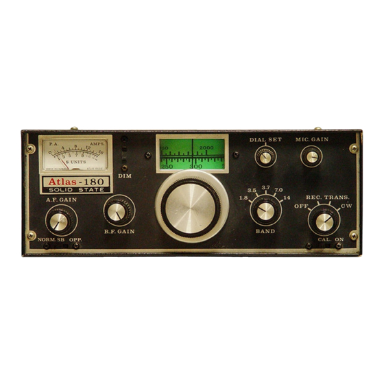
- Page 10 BAND SELECTOR AND THE TUNING DIAL: The first CARRIER BALANCE: A trim pot. is located on the PC- position on the band switch is marked “1.8” for the 1800- 100 plug in board on the right side of the transceiver. Next 2000 kc, or 160 meter band.
- Page 11 TRANS. position every time. The serious CW operator will want Note: High SWR will not damage the Atlas 180. You may feel free to install the semi-break-in accessory kit in the AC console. This to operate.
-
Page 12: Mobile Antennas
52 ohms. With tube type transmitters the Pi matching network will adjust to fairly low impedances, but with a broadband solid state transmitter, such as is used in the Atlas 180, a close impedance match is necessary in order to operate at full power. - Page 13 PC-100A FIRST MIXER, FIRST I.F. AMP. C101,108,109,110,112 10nF 100V disc C102 22pF 10% disc C103 50pF trimmer C104,107 2nF mylar C105 560pF mica C106 160pF mica C111 100nF 50V disc C113 15uF 20V D101,2,3,4,7,8. 1N4148 D105,6. BA182 Q101 2N3866 R101 100R pot R102 10K 0.25W...
- Page 14 PC-200A, SECOND I.F. AMP., SECOND MIXER, MIC. AMP., S-METER AMP. C201,214 15uF 20V R201,220 2k2 0.25W C202,3,5,8,9,210,213 10nF 100V disc R202 220R 0.25W C204,221 100nF 50V disc R203 3K9 0.25W C206 250uF 15V R204 47R 0.25W C207 750pF mica R205 27K 0.25W C212,216,219 1nF 20% disc...
- Page 15 PC-300 RECEIVER AUDIO, OSCILLATOR SWITCH BOARD C301,311 100nF 50V disc R301,4,312 5k6 0.25W C302,4,7,9,12,21,22,23,24 10nF 100V disc R302 27k 0.25W C303 220nF 25V disc R303 100k 0.25W C305 47uF 6V R305 1K5 0.25W C306,314,320 15uF 20V R306,11,15,19,21,22,24 1k 0.25W C308,316,319 2u2 50V R307,8,9,17 470R 0.25W...
- Page 16 PC-400 VFO CIRCUIT BOARD AND TUNING CIRCUITS C401,2,6,7,9 10nF 100V disc R401,413 27R 0.25W C403 300pF s-mica R402,3,9,10 10K 0.25W C404 430pF s-mica R407 22k 0.25W C405 10pF NPO disc R404 470R 0.25W C408 1nF disc R405 680R 0.25W C410 22pF N150 disc R406 15k 0.25W...
- Page 17 PC-500 PRE-AMPLIFIER, DRIVER, POWER AMPLIFIER C501,2,4,7,10,18,19 10nF 100V disc R515 10k bias trim pot C503,9 100nF 50V disc R516 330R 0.25W C505 2nF 600V mylar R517 10R 2W C506,12,17 100nF 100V mylar Q501 MPS6514 C508,16 15uF 20V Q502 2N3866 C511 2.2uF 50V Q503 PT5766 (TRW)
- Page 18 PC-600 CARRIER OSCILLATOR, BUFFER AMPLIFIER C601 200pF 5% silver mica C602 100pF 5% silver mica C603 15pF 10% disc C604,5,6,10,11 10nF 100V disc C607 50pF trimmer (op SB) C608 50pF trimmer (norm SB) C609 10pF 10% disc C612 520pF 5% silver mica R601 22k 0.25W R602...
- Page 19 PC-800 REC. INPUT TUNING, 100 KC CRYSTAL CALIBRATOR C801 680pF 10% C802 50pF trimmer C803 360pF 5% mica C804, 5 3300pF polystyrene C806 270pF 5% mica C807, 8 680pF 5% mica C809 4.7pF disc C810, 13 91pF 5% mica C811, 12 4-40pF trimmer C814 0.047uF mylar...
- Page 20 PC-900 TRANSMITTER INPUT TUNING C901, 4 820pF 5% poly C902, 3 37-250pF trimmer C905 100pF 5% mica C906, 9 180pF 5% mica C907, 8 10-80pF trimmer C910,11,14,16,19 39pF 10% disc C912,13,17,18 4-40pF trimmer C915, 20 4.7pF 10% disc R901, 2 4.7K 10% L901, 2 2.8uH toroid...
- Page 21 PC-1000/1020 LOW PASS FILTERS C1001, 2, 3 2200pF 5% s-mica C1005, 7 820pF 5% s-mica C1006 1300pF 5% s-mica C1008, 10 430pF 5% s-mica C1009 680pF 5% s-mica C1011 330pF 5% s-mica C1012 220pF 5% s-mica L1001, 2 2.9uH toroid L1003, 4 1.8uH toroid L1005, 6...
- Page 22 FOR CW TRANSMISSION: The ALC Control should be set to minimum, or full counterclockwise position. LINEAR AMPLIFIER OPERATION: The illustration on page 9 shows how to connect a linear amplifier to the Atlas 180. ALC output from the linear may be connected to pin 4 on the AUX. plug.
- Page 23 D.C. BATTERY CONNECTIONS: A DELUXE MOBILE MOUNT – (DMK) is available from your Atlas dealer. This plug in design permits easy removal of the transceiver as all needed connections are made to the mount. All necessary hook up cables with polarity protection and hardware are part of the mount. A MOBILE BRACKET KIT –...
Need help?
Do you have a question about the Atlas 180 and is the answer not in the manual?
Questions and answers