Table of Contents
Advertisement
For file reference, please record the following data:
Model No:
Serial No:
Installation Date:
Installation Location:
When ordering replacement parts for your LMI Controller or accessory, please include
the complete Model Number and Serial Number of your unit.
Instruction
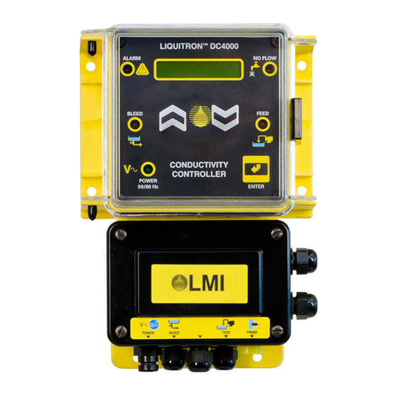
Liquitron™ DC4000 Series
Conductivity Controller
sales@novatech-usa.com
www.novatech-usa.com
Tel: (866) 433-6682
Fax: (866) 433-6684
Tel: (281) 359-8538
Fax: (281) 359-0084
Manual
201 Ivyland Road
Ivyland, PA 18974 USA
TOLL FREE: (800) 564-1097
TEL: (215) 293-0401
FAX: (215) 293-0445
http://www.Imipumps.com
Replaces same of Rev. E 11/99
1732. F 3/2013
1
Advertisement
Table of Contents

Related Manuals for LMI Technologies Liquitron DC4000 Series

Summary of Contents for LMI Technologies Liquitron DC4000 Series
- Page 1 Manual Instruction Liquitron™ DC4000 Series Conductivity Controller For file reference, please record the following data: Model No: Serial No: Installation Date: Installation Location: When ordering replacement parts for your LMI Controller or accessory, please include the complete Model Number and Serial Number of your unit. 201 Ivyland Road Ivyland, PA 18974 USA TOLL FREE: (800) 564-1097...
-
Page 2: Table Of Contents
(866) 433-6682 • (281) 359-8538 • sales@novatech-usa.com • www.novatech-usa.com Contents Introduction............................5 Installation ............................7 Mounting the Controller Enclosure ..................7 Enclosure Mounting Dimensions ..................8 Electrical Wiring Information ....................8 Terminal Strip Layout ......................9 Operating the Controller ......................... 16 Menu Overview ........................ -
Page 3: Introduction
(866) 433-6682 • (281) 359-8538 • sales@novatech-usa.com • www.novatech-usa.com Introduction The DC4000 is a microprocessor-based conductivity controller. It is designed for use in a variety of water treatment applications requiring precise control of total dissolved solids and chemical feed. Among its many uses, the DC4000 will control conductivity and chemical feed in cooling towers, closed loop systems, and boilers. - Page 4 (866) 433-6682 • (281) 359-8538 • sales@novatech-usa.com • www.novatech-usa.com ALARM indicator lights when a warning condition occurs: FLOW indicator lights when BACKLIT • high alarm set point there is a loss of system flow. • low alarm set point Operates only if flow switch DISPLAY •...
-
Page 5: Installation
(866) 433-6682 • (281) 359-8538 • sales@novatech-usa.com • www.novatech-usa.com Installation Mounting the Controller Enclosure The DC4000 conductivity controller is supplied with integral wall-mounting flanges. It should be mounted with the display at eye level on a vibration free surface. All accessibe mounting holes should be utilized. The maximum allow- able temperature is 122°... -
Page 6: Enclosure Mounting Dimensions
(866) 433-6682 • (281) 359-8538 • sales@novatech-usa.com • www.novatech-usa.com Enclosure Mounting Dimensions When using the prewired unit, the enclosure is configured as NEMA 12X. If the unit is connected through watertight conduit, the enclosure is configured as NEMA 4X. The following clearances should be observed for proper mounting (see Figures 2 and 3). Figure 3 Electrical Wiring Information To reduce the risk of electrical shock, the controller must be plugged into a grounded outlet with ratings conforming to... -
Page 7: Terminal Strip Layout
(866) 433-6682 • (281) 359-8538 • sales@novatech-usa.com • www.novatech-usa.com Terminal Strip Layout - DC4000 To access the wiring connections inside of the conductivity controller: 1. Disconnect the unit from electrical power. 2. Remove the four (4) screws and the junction box cover on the lower half of the unit. 3. - Page 8 (866) 433-6682 • (281) 359-8538 • sales@novatech-usa.com • www.novatech-usa.com Terminal Strip Layout - DC4000 Flowmeter Input The inputs are reversible when the flowmeter connection is a relay and has no polarity. Only use flowmeters that do not send power to the controller. TB9-1 TB9-2 Flow Switch Input...
- Page 9 (866) 433-6682 • (281) 359-8538 • sales@novatech-usa.com • www.novatech-usa.com DC4000 Terminal Strip Layout and Wiring Diagram for Accessories Wiring diagram for Boiler Applications with 1/2” Conduit connections Dotted lines represent HARDWIRED Accesories...
- Page 10 (866) 433-6682 • (281) 359-8538 • sales@novatech-usa.com • www.novatech-usa.com DC4000 Terminal Strip Layout and Wiring Diagram for Accessories Wiring diagram for Boiler Applications with 1/2” Conduit connections Dotted lines represent HARDWIRED Accesories...
- Page 11 (866) 433-6682 • (281) 359-8538 • sales@novatech-usa.com • www.novatech-usa.com Flowmeter Input DC4000 Terminal Strip Layout for CE-DC4000 To access the wiring connections inside of the conductivity controller: 1. Disconnect the unit from electrical power. 2. Remove the four (4) screws and the junction box cover on the lower half of the unit.
- Page 12 (866) 433-6682 • (281) 359-8538 • sales@novatech-usa.com • www.novatech-usa.com Flowmeter Input The inputs are reversible when the flowmeter connection is a relay and has no polarity. Only use flowmeters that do not send power to the controller. TB10-1 TB10-2 Flow Switch Input This input can be used to connect a flow switch or other device providing a switch closure output. If a device such as this is connected to the DC4000, it will serve to disable the controller outputs when this switch is in the “OPEN” position. This function can be used as a safety override to prevent controller/pump operation during loss of flow. ...
- Page 13 (866) 433-6682 • (281) 359-8538 • sales@novatech-usa.com • www.novatech-usa.com CE-DC4000 Terminal Strip Layout and Wiring Diagram for Accessories Wiring Diagram for version only Dotted lines represent HARDWIRED Accessories...
-
Page 14: Operating The Controller
(866) 433-6682 • (281) 359-8538 • sales@novatech-usa.com • www.novatech-usa.com Operating the Controller The Conductivity Read Screen or “System Run”: COND : ( µS) 1470 The normal operating display for the DC4000 Series Controller is the conductivity reading screen (as shown above). -
Page 15: Menu Overview
(866) 433-6682 • (281) 359-8538 • sales@novatech-usa.com • www.novatech-usa.com Menu Overview When the “System Run” screen is displayed in the window, the unit automatically switches to the run/operate mode of operation. COND : ( µS) 1470 This “System Run” display line is the top menu page item. Pressing the keys will move the display window to another line item. -
Page 16: Conductivity
(866) 433-6682 • (281) 359-8538 • sales@novatech-usa.com • www.novatech-usa.com Conductivity COND : ( µS)3400 CONDUCTIVITY Conductivity Reading Screen SET POINT The “CONDUCTIVITY” screen displays the conductivity readings in either µSiemens or PPM/TDS (parts per million/total dissolved solids). When the controller is displaying this screen it is considered to be in the SYSTEM RUN mode. -
Page 17: Set Point
(866) 433-6682 • (281) 359-8538 • sales@novatech-usa.com • www.novatech-usa.com Set Point CONDUCTIVITY SET PT 3000 Set Point Screen SET POINT The “SET POINT” screen allows access to the conductivity value that will energize the bleed output relay and allow for the opening of the bleed valve. -
Page 18: Differential
(866) 433-6682 • (281) 359-8538 • sales@novatech-usa.com • www.novatech-usa.com ∆ Differential CONDUCTIVITY ∆ DIFF Differential or Dead Band SET POINT The “DIFFERENTIAL” or dead band setting allows for a hysteresis to be programmed in to the conductivity trip point. A programmed hysteresis value prevents the bleed relay and solenoid from cycling on and off repeatedly ∆... -
Page 19: Low Alarm
(866) 433-6682 • (281) 359-8538 • sales@novatech-usa.com • www.novatech-usa.com Low Alarm CONDUCTIVITY LO ALARM SET POINT Low Conductivity Alarm Set Point The “LOW ALARM” screen allows programming of the Low Conductivity reading that activates an alarm LED and output relay. ∆... -
Page 20: High Alarm
(866) 433-6682 • (281) 359-8538 • sales@novatech-usa.com • www.novatech-usa.com High Alarm CONDUCTIVITY HI ALARM 4000 SET POINT High Conductivity Alarm Set Point The “HIGH ALARM” screen allows programming of the High Con- ductivity reading that activates an alarm LED and output relay. ∆... -
Page 21: Feed
(866) 433-6682 • (281) 359-8538 • sales@novatech-usa.com • www.novatech-usa.com Feed FEED (MODE) CONDUCTIVITY Feed Pump Screen SET POINT The “FEED” screen displays the current Inhibitor Feed Pump mode selected. There are four different FEED modes that may be selected from. The cur- rent active mode is displayed in parenthesis. -
Page 22: Manual Outputs
(866) 433-6682 • (281) 359-8538 • sales@novatech-usa.com • www.novatech-usa.com Manual Outputs MANUAL OUTPUT CONDUCTIVITY Manually Energize Relay Outputs SET POINT The “MANUAL OUTPUTS” mode is provided to allow for manual energizing of each relay output. Once the external devices have been connected, they may be individually or collectively energized and tested. -
Page 23: Advanced Setup
(866) 433-6682 • (281) 359-8538 • sales@novatech-usa.com • www.novatech-usa.com Advanced Setup ADVANCED SETUP CONDUCTIVITY The “ADVANCED SETUP” screens allow for the special configuring of the controller for advanced options. These options include: SET POINT • FLOW ALARM (energizing the alarm output relay on loss of flow); •... -
Page 24: Temperature
(866) 433-6682 • (281) 359-8538 • sales@novatech-usa.com • www.novatech-usa.com 3.10 Temperature CONDUCTIVITY TEMP (F) 032° SET POINT The “TEMPERATURE” screen displays the temperature sensed by the externally connected thermistor [10K Ohms at 77° F / 25° C] in the Cooling Tower probe. The screen may display temperature in either ∆... -
Page 25: O Meter
(866) 433-6682 • (281) 359-8538 • sales@novatech-usa.com • www.novatech-usa.com 3.11 O Meter TOTAL (00000) GAL CONDUCTIVITY Water Meter Totalizer Screen SET POINT The “WATER METER TOTAL” screen allows for the display of the total gallons accumulated through a flow meter. The submenu allows for the programming of the: 1) water meter pulses-to-gallons (liters) ratio;... -
Page 26: Boiler
(866) 433-6682 • (281) 359-8538 • sales@novatech-usa.com • www.novatech-usa.com 3.12 Boiler The DC4000 Controller is shipped from the factory set in the “COOL- ING TOWER” mode. Select “BOILER” mode in “ADVANCED” menu CONDUCTIVITY to change this. CONDUCTIVITY SET POINT SET POINT ∆... - Page 27 (866) 433-6682 • (281) 359-8538 • sales@novatech-usa.com • www.novatech-usa.com 3.12 Boiler (cont’d) CONDUCTIVITY DURATION 120 SECONDS SAMPLE TIME (MINUTES) ENTER Boiler OFF time Boiler Blowdown time If “TRAP SAMPLE” is selected for “TIMED SAMPLING”, the operator SET POINT will be prompted to program the amount of trap time. TRAP TIME SECONDS ∆...
-
Page 28: Start-Up
(866) 433-6682 • (281) 359-8538 • sales@novatech-usa.com • www.novatech-usa.com Start-Up Cooling Tower Installation The DC4000 Series of conductivity controller should be installed based upon the recommended system diagram below. A bypass loop for open recirculating water systems is the best method of conductivity monitoring and control. The conductivity sensing electrode used with the conductivity controller must receive an active representative sample of system water. -
Page 29: Cooling Tower Installation
(866) 433-6682 • (281) 359-8538 • sales@novatech-usa.com • www.novatech-usa.com The DC4000 can be programmed for a variety of different tasks. Before start-up can be completed, certain information must be decided regarding the controller programming. The following work sheet should be filled out in advance to aid in the programming of the controller. The single most important decision is whether the controller will be used for cooling tower, boiler, or closed loop control. -
Page 30: Boiler Installation
(866) 433-6682 • (281) 359-8538 • sales@novatech-usa.com • www.novatech-usa.com Once the operating settings and parameters have been determined by the data entered above, the DC4000 Controller can then be programmed. Supply power to the controller. Read the conductivity and verify the accuracy using a calibrated meter and conductivity sample. -
Page 31: Timed Sampling Mode
(866) 433-6682 • (281) 359-8538 • sales@novatech-usa.com • www.novatech-usa.com Timed Sampling Mode Used in small to medium sized boilers where the blowdown requirements are less than 5000 lbs/hr. A boiler this size or smaller cannot be sampled continuously because the volume of water (blowdown) lost to sampling would prevent the conductivity from rising above the set point. -
Page 32: Boiler Start-Up
(866) 433-6682 • (281) 359-8538 • sales@novatech-usa.com • www.novatech-usa.com Additional equipment required to complete installation for a CONTINUOUS sample method of control: Fully ported shut off valve for blowdown line. Allows for the removal of the electrode while the boiler is on. Adjustable flow control valves or orifice unions with various sized plates. - Page 33 (866) 433-6682 • (281) 359-8538 • sales@novatech-usa.com • www.novatech-usa.com Figure 7: Timed Sample Figure 8: Continuous Sample...
-
Page 34: Continuous Sample Start-Up
(866) 433-6682 • (281) 359-8538 • sales@novatech-usa.com • www.novatech-usa.com 4.10 Continuous Sample Start-Up 1. Check that the unit is installed as shown in Figure 8 Continuous Sample on page 30. 2. Complete the Pre-Start-Up Work Sheet on page 26. 3. Supply power to the DC4000 controller, read the conductivity and verify accuracy using a calibrated meter and sample. -
Page 35: Closed Loop Installation Notes
(866) 433-6682 • (281) 359-8538 • sales@novatech-usa.com • www.novatech-usa.com 4.13 Closed Loop Installation Notes As in a cooling tower application, the probe should be installed in a bypass sample stream. The probe should be isolated by valves to allow for removal while the system is on. Any chemical injection must take place downstream of the probe. Refer to Figure 9 below for location of components. - Page 36 (866) 433-6682 • (281) 359-8538 • sales@novatech-usa.com • www.novatech-usa.com If the probe reading is off by more than 50%, then the controller will indicate an error by displaying ‘CAL LIM µS‘. This generally means that the probe has failed or needs cleaning. Alternately, a sample of cooling tower water may be analyzed by a precalibrated conductivity monitor, and the DC4000 controller calibrated to match that reading using the sample as a standard solution.
-
Page 37: Maintenance
(866) 433-6682 • (281) 359-8538 • sales@novatech-usa.com • www.novatech-usa.com Maintenance Controller The DC4000 controller itself requires very little maintenance. Wiping the controller down with a damp cloth will clean it. Do not spray down the controller unless the enclosure door is closed and latched. Probe The controller must be recalibrated after cleaning the probe. -
Page 38: Troubleshooting
(866) 433-6682 • (281) 359-8538 • sales@novatech-usa.com • www.novatech-usa.com Troubleshooting Disconnect power to the controller before opening the front panel! Troubleshooting and repair of a malfunctioning controller should only be attempted by qualified personnel using caution to insure safety and to limit unnecessary further damage. -
Page 39: Factory Settings
(866) 433-6682 • (281) 359-8538 • sales@novatech-usa.com • www.novatech-usa.com Factory Settings Temperature ....Fahrenheit % Time - ......10% Feed after Bleed ......10% Conductivity Set point ..2000 µS Delta Differential ....100 µS Feed after Bleed - Limit ....10 minutes Low Alarm ....100 µS Limit (Feed &... -
Page 40: 10.0 Product Exploded View
(866) 433-6682 • (281) 359-8538 • sales@novatech-usa.com • www.novatech-usa.com 10.0 Product Exploded View... -
Page 41: Product Parts List
(866) 433-6682 • (281) 359-8538 • sales@novatech-usa.com • www.novatech-usa.com 11.0 Parts List Part Description 34675 Housing, Machined 32186 Screw, 4-40 x .37 3 32187 Nut, 4-40 Flush 32209 Latch, Machined 5 34710 I/O Board Assembly 31632 Screw, #6 x .38 34716 Standoff, Self Adhesive 25990 Connector Assembly 33566... -
Page 42: Warranty
(866) 433-6682 • (281) 359-8538 • sales@novatech-usa.com • www.novatech-usa.com 12.0 Statement of Limited Warranty LMI TERMS AND CONDITIONS OF SALE: Visit the LMI web site at www.lmipumps.com for warranty details. - Page 43 sales@novatech-usa.com www.novatech-usa.com Tel: (866) 433-6682 Fax: (866) 433-6684 Tel: (281) 359-8538 Fax: (281) 359-0084 201 Ivyland Road Ivyland, PA 18974 USA TOLL FREE: (800) 564-1097 TEL: (215) 293-0401 FAX: (215) 293-0445 http://www.Imipumps.com © 2013 Milton Roy, LLC - All Rights Reserved. Liquitron is a trademark of Milton Roy, LLC Specifications subject to change without notice.
Need help?
Do you have a question about the Liquitron DC4000 Series and is the answer not in the manual?
Questions and answers