Table of Contents
Advertisement
Quick Links
Advertisement
Table of Contents

Summary of Contents for Love Controls Loop Alarm
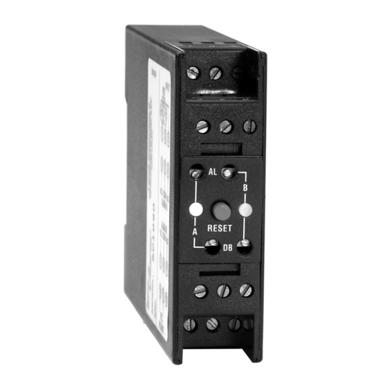
- Page 1 Loop Alarm™ Models SC1090 and SCL1090 INSTALLATION INSTRUCTIONS LOVE CONTROLS LOVE a Division of Dwyer Instruments, Incorporated PO Box 338 Michigan City, IN 46361-0338 ® (800) 828-4588 (219) 879-8000 FAX (219) 872-9057 www.love-controls.com 949-0529 Rev. 2 Page 1 of 8...
-
Page 2: Getting Started
5.) Check calibration (See Calibration on page 6). Operation description is on page 6 Specifications are on page 7. Copyright © 2004 Love Controls Division, Dwyer Instruments, Inc. All rights reserved. December, 2004 Page 2 of 8 949-0529 Rev. 2... - Page 3 INPUT PROGRAMMING Use the following chart to select the input type and range for your process. Turn on the appropriate switch(s) (as indicated) on SW1 for the input and SW4 for the range desired. 1 2 3 4 5 6 7 8 RANGE SELECTION CHART INPUT 1 2 3 4...
- Page 4 OUTPUT PROGRAMMING Setup of the alarms is fairly simple once a few concepts are under- stood. Since the alarms can be set for reverse or direct action, high or low function, and has normally open and normally closed contacts; the number of combinations of actual output behavior is quite large.
- Page 5 Using the figure below, set up the switches on SW2 for Alarm A and Alarm B. For dual alarm relays triggered by Alarm A, set switch 5 to DUAL. When switch 5 is set to DUAL (on), switches 6 and 7 have no effect. OUTPUT MODE 5 6 7 8...
- Page 6 ALARM CALIBRATION NOTE: Allow the module and socket to come to stable temperature before proceeding. For best results, allow the module to be powered in the socket for at least 20 minutes. 1. Apply the appropriate input for the desired alarm trip point.
-
Page 7: Specifications
SPECIFICATIONS Power Supply: SC1090: 85 to 265 Vdc/Vac 50 to 400 Hz. SCL1090: 12 to 24 Vdc/Vac 50 to 400 Hz. ±20% Isolation: 1500 V rms between outputs, input, and power. Set Points: Adjustable 0 to 100% of span. Deadband: Adjustable 0.25% to 100% of span. Drift: ±0.02% / °C typical, ±0.05% / °C maximum. - Page 8 NOTES December, 2004 Page 8 of 8 949-0529 Rev. 2...
Need help?
Do you have a question about the Loop Alarm and is the answer not in the manual?
Questions and answers