Table of Contents
Advertisement
Advertisement
Table of Contents

Summary of Contents for Radiopost TS401
- Page 1 User Manual for 4 Channel Transmitter TS401 2.4GHz...
-
Page 2: General Information
FM band, Radiopost‟s TS401 2.4GHz system is free from interference to respond more quickly and accurately. Radiopost TS401 2.4GHz is designed for all kinds of RC cars and boats. Whether it is on-road or off-road, at a pond or lake, Radiopost‟s products are made for various RC hobbyists. -
Page 3: Safety
■ Safety Before using the TS401 2.4GHz system, please carefully and thoroughly read this manual in order to use your RC system safely. Use this product in a safe manner, observing all safety precautions at all times. Please follow and observe all additional rules at the place of operation as suggested (i.e. - Page 4 ▶ Please check if the batteries for transmitter and receiver are fully charged before starting. ▶ The antenna for Radiopost‟s transmitter TS450 2.4GHz is built-in the product (Internal). The antenna in located underneath the front top section, above the power switch of the transmitter. Be careful not to cover this part of transmitter, as it may cause weak signal output if covered.
- Page 5 Warning ▶ Use five AA-size dry cell batteries, five AA-size rechargeable batteries, or its equivalents only. Batteries other than specified above may cause serious damages on your TS401. Misuse of battery may void warranty.
-
Page 6: Table Of Contents
Table of Contents ■ General Information ■ Safety ■ Precautions & Warnings 1. Before Using 1.1 Features 1.2 Parts and Accessories 1.3 Nomenclature 1.4 Welcome Screen 1.4.1 Vertical View 1.4.2 Horizontal View 2. Personal Adaptation 2.1 How to Remove and Attach the Adapter for Wheel Extension 2.2 How to Change the Wheel Angle 2.3 How to Change the Wheel Position for the Left-handed Use 3. - Page 7 5.7 Reverse 5.8 Bind Receiver 5.9 Selection of Switch 5.9.1 Push Switch 5.9.2 Dial Switch 5.9.3 Trim Switch 5.10 Speed 5.10.1 Steer Speed 5.10.2 Throttle Speed 5.11 Brake 5.12 Monitor 5.13 Adjust 5.14 Timer 5.15 LAP List 5.16 Edit Banner 5.17 System 5.18 Advanced 5.18.1 Throttle Mode...
-
Page 8: Before Using
1. Before Using 1.1 Features ▣ 2.4GHz radio communication system Frequency channel setting unnecessary and channel shifting takes place within the 2.4GHz band automatically. This system minimizes the interference from other 2.4GHz systems by using DSSS that has high signal transmission rate. ▣... - Page 9 ▣ Racing timer The racing timer can record total time and average lap time. The race time and audible alarm can be set. ▣ Tension adjustment function The tension of the steering wheel & throttle trigger springs can be adjusted from the outside. ▣...
-
Page 10: Parts And Accessories
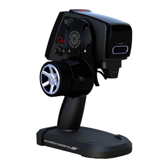
4Ch. Surface Transmitter RP24RS5D Receiver 5Ch. Receiver Battery Holder Holder for AA Battery Wheel Holder Holder for Wheel Set Wire Wire Used with Wheel Set Screw Screws for Wheel Holder Used for Personal Hex Wrench Adaptation User Manual User Guide for TS401... -
Page 11: Nomenclature
1.3 Nomenclature LED WINDOW* DIGITAL DIAL 3 (DL3) ADAPTER FOR LCD SCREEN WHEEL EXTENSION DIGITAL TRIM 1 (DT1) EDIT BUTTONS DIGITAL TRIM 2 (DT2) STEERING WHEEL <LED Colors> RED: Lights if RF is turned off. GREEN: Lights if a receiver is bound. ... - Page 12 EMPTY WHEEL COVER PUSH POWER SWITCH 1 (PS3) SWITCH DIGITAL DIAL 1 (DL1) DIGITAL DIAL 2 (DL2) THROTTLE TRIGGER PUSH SWITCH 2 (PS2) GRIP HANDLE...
- Page 13 PUSH SWITCH 1 (PS1) DIGITAL TRIM 3 (DT3) TRIGGER WHEEL TENSION TENSION ADJUSTING ADJUSTING SCREW SCREW TRIGGER SLIDE BATTERY ADJUSTING SCREW COVER...
-
Page 14: Welcome Screen
1.4 Welcome Screen 1.4.1 Vertical View 1) Normal Option Screen Battery Indication Model Number Banner Display Model Name Logo Display Dial 1 Indication Trim Button 1 Indication Dial 2 Indication Trim Button 2 Indication Dial 3 Indication Trim Button 3 Indication Steer Trim Throttle Trim... -
Page 15: Horizontal View
1.4.2 Horizontal View 1) Normal Option Screen Battery Indication Model Number & Name Dial 1 Indication Dial 2 Indication Trim Button 3 Indication Steer Trim Trim Button 1 Trim Button 2 Throttle Trim Indication Indication 2) Time Option Screen Battery Indication Model Number &... -
Page 16: Personal Adaptation
2. Personal Adaptation Caution TS401 2.4GHz can be adapted according to the user‟s preference. Be sure to POWER OFF before making any changes or preference setting. 2.1 How to Remove and Attach the Adapter for Wheel Extension The wheel position of TS401 can be changed using the adapter for wheel extension. - Page 17 5. Detach the adapter from the transmitter body and disconnect the wire. 6. Attach the wheel holder separately provided. 7. Screw in the 4 screws on the wheel holder. These screws are separately provided. 8. Plug in the wire to the transmitter body.
-
Page 18: How To Change The Wheel Angle
11. Assemble the wheel by driving the center screw. 2.2 How to Change the Wheel Angle The wheel angle of TS401 with the adapter for wheel extension assembled can be modified for the user‟s preference. 1. Take off the 4 screws on the adapter neck. -
Page 19: How To Change The Wheel Position For The Left-Handed Use
2.3 How to Change the Wheel Position for the Left-handed Use The default set of TS401 wheel is for the right-handed use. The wheel position can be easily modified for the left-handed persons. 1. Take off the 4 screws on the adapter neck and disconnect the wire. -
Page 20: Functions And Description Of Buttons
3. Functions and Description of Buttons 3.1 Edit Buttons There are 7 Edit Buttons such as Navigation (UP and DOWN/ Left and RIGHT and SET ), MENU and BACK. Edit Buttons have two type of Modes: Normal or Edit. Normal Mode is for selecting items, and Edit Mode is for saving the edited values. -
Page 21: Trim Buttons
3.2 Trim Buttons There are 3 Trim Buttons such as DT1, DT2 and DT3. Button Name Description Press the DT1 to the left direction to decrease the setting value of the allocated function. Press the DT1 to the right direction to increase the setting value of the allocated function. -
Page 22: Push Switches
3.4 Push Switches There are 3 Push Switch such as PS1, PS2 and PS3. Switch Name Description Press the PS1 to activate the allocated function of the switch. Press the PS2 to activate the allocated function of the switch.. Press the PS3 to activate the allocated function of the switch. PS3 has On status and Off status. -
Page 23: All Menu
4.2 All Menu Depth 1 Depth 2 Menu Model Model Select Model Name Model Copy Model Reset Subtrim Dual Rate EPA 1 EPA 2 Exponential Steer Exponential Throttle EXP Reverse Bind Receiver Switch Select Switch Dial Trim Switch Speed Steer Speed Throttle Speed Brake Monitor... -
Page 24: Description Of Functions
5. Description of Functions 5.1 Model 5.1.1 Model Select Transmitter can save up 20 different models. Select your model(s) in the menu displayed below. ■ How to Set Move to the model number by using the directional (LEFT/ RIGHT/ UP/DOWN). Press the SET to select the model. 5.1.2 Model Name Use the “Model Name”... -
Page 25: Model Copy
Use the directional (LEFT/RIGHT/UP/DOWN) to select a character and press the SET to confirm. Repeat to change other characters as needed. 5.1.3 Model Copy Use the Model Copy function to copy the data value of your selected model onto another model. ■... -
Page 26: Model Reset
5.1.4 Model Reset Use the “Model Reset” to initialize the current model's input values (DR, ATL, EPA, ST-EXP, TH-EXP, Brake, etc.). ■ How to Set Select the model you want to reset in "Model Select" menu by selecting the "Model Reset" menu. Select "Yes" and press SET to reset current model's input value to the default value. -
Page 27: Dual Rate
■ How to Set Use the UP/DOWN to move to the preferred channel, then press the SET. Change the trim value with LEFT and RIGHT. Adjust subtrim value to center the servo at the neutral position. After the adjustment, press the SET to save the changed value. 5.3 Dual Rate Adjust the maximum end point of the steer servo. -
Page 28: Epa
Use the “STR-LEFT” to set the maximum left end point of steer channel. Use the “STR-RIGHT” to set the maximum right end point of steer channel. Use the “THR-FWD” to set the maximum end point toward the forward direction of throttle channel. Use the “THR-BRAKE”... -
Page 29: Exponential
■ How to Set Use UP/DOWN to move to preferred channel, then press SET. Change trim value with LEFT and RIGHT. After adjustment, press SET to save the changed value. 5.6 Exponential 5.6.1 Steer Exponential Use the “Steer Exponential” to adjust the movement in neutral. If the steer exponential value is less than “0”, the response of control will be slower. -
Page 30: Throttle Exp
5.6.2 Throttle EXP Use the Throttle EXP to adjust the movement of throttle (Accelerator/ Brake) channel. The direction of accelerator and brake is separately adjustable. The channel movement of accelerator direction is adjustable as following 3 types. • EXP: Adjust the sensitivity of movement in neutral by using exponential curve. - Page 31 • VTR: Press the SET on TYPE and select VTR. Press the DOWN to move to FWD. • FWD: Press the SET on FWD, and set the trigger point value by using LEFT and RIGHT. Press the SET to save the changed value.
-
Page 32: Reverse
Set FWD for each 3 (1,2,3) trigger points. Press the SET on “1:” and adjust the value by using the LEFT and RIGHT. After adjustment, press the SET to save the adjusted value. Press the DOWN to move to “2:” and “3:” Setting methods of “2:” and “3:” are the same as “1:”. -
Page 33: Bind Receiver
5.8 Bind Receiver This function is used to bind a new receiver to the transmitter. ■ How to Set Turn on the power to receiver, press and hold down the ID button of the receiver until it goes into binding mode. Press the SET on the transmitter to go into binding mode with the message "Wait until Bound”... - Page 34 Caution If the RF transmitter is set as OFF, the transmitter does not go into the binding mode with the message “Enable RF First” displayed on the screen. In this case, go to the System Menu and set the Radio TX as On for binding.
-
Page 35: Selection Of Switch
5.9 Selection of Switch 5.9.1 Push Switch There are 3 push switches on the transmitter: PS1, PS2 and PS3. The functions shown in the below table can be assigned to each push switch. The default setting of push switches is OFF. The table shows the functions that can be assigned to the push switches. -
Page 36: Dial Switch
5.9.2 Dial Switch There are 3 dial switches on the transmitter: DL1, DL2 and DL3. These functions shown in the table below can be assigned to each dial switch. The default setting of DL1 is TRMT, DL2 is EXPF and DL3 is OFF. - Page 37 Item Functions SBT1 Sub trim (CH1) SBT2 Sub trim (CH2) SBT3 Sub trim (CH3) SBT4 Sub trim (CH4) IDLE Idleup TL13 Tilt Mixing (13) TL31 Tilt Mixing (31) PM1A Program Mix 1 (LEFT/FWRD/UP sides) PM1B Program Mix 1 (RIGHT/BRAKE/DOWN sides) PM2A Program Mix 2 (LEFT/FWRD/UP sides) PM2B...
-
Page 38: Trim Switch
5.9.3 Trim Switch There are 3 digital trim switches on the transmitter: DT1, DT2 and DT3. The preferred functions can be assigned to each trim switch. The default setting of DT1 is TRMS, DT2 is D/R and DT3 is EXPS. All the functions for the dial switches as shown in the table of the Dial Switch section can be assigned to the trim switches. -
Page 39: Speed
5.10 Speed 5.10.1 Steer Speed Abrupt steering may cause excessive or insufficient rotation of vehicle and possibly cause deceleration. To prevent unexpected results, it is suggested to adjust the reaction speed of the steering. ■ How to Set Select whether to adjust the value of start turn direction or to adjust the value of rotation return direction, and then press the SET. - Page 40 ■ How to Set Select Speed 1 in the Mode. Move to All by using the DOWN and press the SET. The value can be changed using the LEFT and the RIGHT. After finishing the adjustment, press the SET to save the changed value.
- Page 41 Speed 3 Speed is set as the direction of throttle acceleration is divided into the low range, the mid range and the high range on the basis of two trigger points. ■ How to Set Select Speed 3 in the Mode. Move to Low using the DOWN and press the SET.
-
Page 42: Brake
5.11 Brake This function is used to operate the brake system of front wheels and the brake system of rear wheels separately. The brake of rear wheels can be connected to the Ch. 2 and the brake of front wheels can be connected to the Ch. - Page 43 Move to the Brake-EXP using the DOWN to set the exponential value. The range of exponential value is -100 to 100. The default value is 0. When the value is negative (-), the motion around the neutral position becomes dull. When the value is positive (+), the motion around the neutral position becomes sensitive.
- Page 44 Move to ABS-Mode in the next page by pressing the DOWN on the STM-RIGHT. The default setting of ABS-Mode is INH. In the INH state, the mixing value cannot be set because the slot for value setting is blocked by the mark „---„. In order to activate the ABS-Mode, change INH to ACT first.
-
Page 45: Monitor
5.12 Monitor This function is to display the position of servo which is detected by the transmitter. The 4 channels are displayed in order. Ch.1 is for steering, Ch.2 is for throttle, and Ch.3 and Ch.4 are in reserve. Current MENU Channel 1 Steer Channel 2 Throttle Channel 3... - Page 46 ■ How to Set Select Steer. Put the steering wheel on the neutral position and press the SET. Turn the steering wheel to the left end and to the right end to make the maximum values recognized. Press the SET to save the neutral position value, the left maximum value and the right maximum value.
-
Page 47: Timer
Move the throttle to the forward end and to the backward end to make the maximum values recognized. Press the SET to save the neutral position value, the Forward maximum value and the Brake maximum value. 5.14 Timer 4 different types of timer are available. (UP, DOWN, LAP, LAP Navigate) Current MENU UP/DOWN/LAP/ LAP navigate... - Page 48 UP Timer The timer‟s range is 0 to 99.9999 minutes. Alarms can be set in 1 minute increments. Pre-alarms can be set in 1 second increments. When the timer reaches the set alarm time, alarm sound is made. When a pre-alarm is set, the warning sound beeps for the set pre-alarm period before the timer reaches the set alarm time.
- Page 49 ■ How to Set the Timer (Same with that of UP Timer) Move to TYPE using the UP/DOWN and press the SET. Then, select PUEL Down and press the SET. Move to ALRM using the DOWN and press the SET. Set the alarm time and press the SET.
-
Page 50: Lap List
LAP TIME. 5.16 Edit Banner The user can edit the top line banner on the welcome screen. Using capital or lower case letters and other marks (!"#$%&'()*+,-./:;<=>?@[\]^_ `{|}~), 15 characters in maximum can be input. The default banner is Radiopost. -
Page 51: System
■ How to Set Move to the place to be changed using the LEFT and the RIGHT. Press the SET to display the character box and use the navigation keys to move to different letters symbols in the cursor box. Move to the character to be input using the direction buttons (LEFT/RIGHT/UP/DOWN) and press the SET. - Page 52 LCD Backlight This function is used to reduce battery consumption. If the user does not press the EDIT button for a specified period, the power of LCD screen turns off. Setting Values Description Always On The LCD screen is always on. 30 Seconds Turned off after 30 seconds.
- Page 53 Auto-Alert This function creates a warning sound to let the user know that the transmitter has been idle with the power on. Setting Values Description No warning sound. 5 Minutes Warning sound after 5 minutes. 10 Minutes Warning sound after 10 minutes. 15 Minutes Warning sound after 15 minutes.
-
Page 54: Advanced
Radio TX This function sets the transmitter to send RF or not. If it is set as OFF, the transmitter does not send any data to the receiver. Setting Values Description Power is on to the RF part, the data are transmitted. Power is off to the RF part, the data are not transmitted. -
Page 55: Abs
5.18.2 ABS While cornering with brake on, the vehicle may be push and lose traction. Such pushing can be prevented using ABS function. ■ How to Set This function is initially inhibited (INH). Press the SET on Mode and then press the RIGHT to change the value to ACT. Press the SET again to activate the function. -
Page 56: Th-Acceleration
Move to DTY using the DOWN to set the brake pulse duty value. Duty is the ratio between the brake-on time and brake-off time. DTY value can one of -3, -2, -1, 0, 1, 2, 3. The smaller value is, the longer the brake-on time is. -
Page 57: At-Start
If the Brake is mixed to the 3 channel and 4 channel, throttle acceleration can be applied to them separately and it works independently according to the set values. 5.18.4 AT-Start If the road is slippery and the throttle trigger is pulled abruptly, the car will spin with no traction. -
Page 58: Idle-Up
Caution ATS will go back to Off state if start function is operated by throttle movement. In case that this function is required in next start, user needs to set ATS to Ready again. ■ How to Set Press SET when placed in Mode, and use RIGHT to select AT. Press SET again to activate the function. -
Page 59: Atl
■ How to Set Press SET, and use the LEFT and/or the RIGHT to modify the values. Press SET again to save the value. The value can be modified to 100 toward the up side and to 100 toward the down side. The default is 0, which means the neutral point. -
Page 60: Aux Ch Position
5.18.7 AUX CH Position It is used to change the position of auxiliary channels. (the 3 channel and the 4 channel.) Auxiliary channels can be assigned to the Dial Switches or Trim switches for instant change. ■ How to Set Move to the channel which is desired to change the position. -
Page 61: Prog Mix
■ How to Set Press the SET when placed in TRG-BRK, and use the RIGHT to modify it to Cut Off. Press the SET again to save it. Move to Mode using the DOWN. Press the SET and use the RIGHT to change it to On. - Page 62 Move to MST using the DOWN twice. Press the SET and select the slave channel using the LEFT and the RIGHT. Press the SET again to save the slave channel. Move to the Left (Or FWRD) by pressing the UP three times. Press the SET and use the LEFT and the RIGHT to modify the mix rate.
- Page 63 ■ System Specifications Transmitter Receiver Model TS401 Model RP24RS5D Frequency 2.4GHz Band DSSS Frequency 2.4GHz Band DSSS Operating Voltage Operating Voltage 4.6V ~ 12.6V 5AA Alkaline Power Supply Weight 7.5g Dry Cell DC 7.2V Weight 646g...
-
Page 64: Troubleshooting Guide
■ Troubleshooting Guide Troubles Causes Troubleshooting No battery or not Unable to transmit the radio. Charge the battery. enough voltage. Alarm sounds Low voltage of battery. Charge the battery. continuously. Alarm does not Alarm sounds The interval timer is Turn “OFF” stop. -
Page 65: Abbreviation
■ Abbreviation Abbreviation Meaning NT-BRAKE Neutral Brake Anti-Lock Brake System PROG MIX Programmable Mix Dual Rate EXPS Steer Exponential EXPF Throttle Exponential (Forward side) EXPB Throttle Exponential (Brake side) EXP3 Brake Exponential for Channel 3 EXP4 Brake Exponential for Channel 4 SPTn Steer Speed (Turn side) SPRn... -
Page 66: Warranty
(c) Purchaser Remedy‐ Radiopost's sole obligation hereunder shall be that Radiopost will, at its option, (i) repair or (ii) replace, any Product determined by Radiopost to be defective. In the event of a defect, these are the Purchaser's exclusive remedies. - Page 67 Ship via a carrier that provides tracking and insurance for lost or damaged parcels, as Radiopost is not responsible for merchandise until it arrives and is accepted at our facility.
- Page 68 Federal Communication Commission Interference Statement This equipment has been tested and found to comply with the limits for a Class B digital device, pursuant to Part 15 of the FCC Rules. These limits are designed to provide reasonable protection against harmful interference in a residential installation. This equipment generates, uses and can radiate radio frequency energy and, if not installed and used in accordance with the instructions, may cause harmful interference to radio communications.
- Page 69 ■ Contact Radiopost, Inc. 26445 Rancho Parkway South. Suite B Lake Forest, CA 92630 USA T. 949.273.8282 / 888.947.5551 F. 949.273.8285 / 888.947.5557 www.radiopost.com...
Need help?
Do you have a question about the TS401 and is the answer not in the manual?
Questions and answers