Table of Contents
Advertisement
Quick Links
TimeProvider 2700 Edge Grandmaster Clock
....................
TimeProvider 2300 Edge Boundary Clock
....................
.....................................................................................................
.....................................................................................................Revision A3 ‐ July, 2013
...........................................................................................
User's Guide updates are available at:
www.symmetricom.com
User's Guide
Part Number 098‐00564‐000
Advertisement
Table of Contents
Troubleshooting

Related Manuals for Symmetricom TimeProvider 2700

Summary of Contents for Symmetricom TimeProvider 2700
- Page 1 TimeProvider 2700 Edge Grandmaster Clock ....TimeProvider 2300 Edge Boundary Clock .... User’s Guide ..........................................Revision A3 ‐ July, 2013 ................... Part Number 098‐00564‐000 User’s Guide updates are available at: www.symmetricom.com...
- Page 2 © 1999 ‐ 2013 Symmetricom, Inc. All rights reserved. Printed in U.S.A. All product names, service marks, trademarks, and registered trademarks used in this document are the property of their respective owners. ...
-
Page 3: Table Of Contents
Contents Purpose of This Guide ......... . .16 Who Should Read This Guide. - Page 4 Table of Contents Rack Mounting the TimeProvider 2300/2700 ......43 Making Ground and Power Connections ......45 Ground Connections .
- Page 5 Table of Contents set hostname ..........87 show image .
- Page 6 Table of Contents upgrade ..........170 show user .
- Page 7 Table of Contents Provisioning the Non-PTP Outputs ....... . .220 Quality Levels for Output Signals .
- Page 8 Table of Contents Troubleshooting ..........253 Diagnosing the TP 2300/2700 By Symptom .
- Page 9 Table of Contents Factory Defaults ..........312 TP 2300/2700 Defaults .
- Page 10 Table of Contents TimeProvider 2300/2700 User’s Guide 098-00564-000 Revision A3 – July, 2013...
- Page 11 Figures TimeProvider 2700 DC Version Connectors and LEDs ....27 TimeProvider 2700 AC Version Connectors and LEDs ....27 TimeProvider 2300 DC Version Connectors and LEDs .
- Page 12 List of Figures Fixed VLAN for Client Port— Set Vlan Commands ....197 Set Ref Command Hierarchy........198 PQL Input and Output Mapping .
- Page 13 TimeProvider 2300/2700 LAN Port Specifications ....296 TimeProvider 2700 GNSS Input Signal Specifications ....296 TimeProvider 2300/2700 DS1 Input Signal Specifications.
- Page 14 GNSS Port Alarm Parameters ........322 GNSS Antenna Kits for TimeProvider 2700 ......333 LMR-400 Antenna Coaxial Cable Accessories .
-
Page 15: How To Use This Guide
How to Use This Guide This section describes the format, layout, and purpose of this guide. In This Preface Purpose of This Guide Who Should Read This Guide Structure of This Guide Conventions Used in This Guide ... -
Page 16: Purpose Of This Guide
Purpose of This Guide The TimeProvider 2300/2700 User’s Guide describes the procedures for unpacking, installing, using, maintaining, and troubleshooting the Symmetricom TimeProvider 2700 Precision Timing Protocol Grand Master and TimeProvider 2300 Carrier-Class Boundary Clock. It also includes appendixes that describe alarms and events, the languages that you use to communicate with the TimeProvider 2300/2700, default values, and other information. - Page 17 How to Use This Guide Structure of This Guide Chapter, Title Description Chapter 4, Provisioning Describes the commands and procedures required to provision the TimeProvider 2300/2700 after installing the unit. Chapter 5, Maintenance and Contains preventive and corrective maintenance, and Troubleshooting troubleshooting procedures for the product.
-
Page 18: Conventions Used In This Guide
You must enter status commands for case-sensitive operating systems exactly as shown. personnel A word or term being emphasized. qualified Symmetricom does not A word or term given special emphasis. recommend... TimeProvider 2300/2700 User’s Guide 098-00564-000 Revision A3 – July, 2013... -
Page 19: Warnings, Cautions, Recommendations, And Notes
How to Use This Guide Warnings, Cautions, Recommendations, and Notes Warnings, Cautions, Recommendations, and Notes Warnings, Cautions, Recommendations, and Notes attract attention to essential or critical information in this guide. The types of information included in each are explained in the following examples. Warning: To avoid serious personal injury or death, do not disregard warnings. -
Page 20: Related Documents And Information
How to Use This Guide Related Documents and Information Related Documents and Information See your Symmetricom representative or sales office for a complete list of available documentation. To order any accessory, contact the Symmetricom Sales Department. See http://www.symmetricom.com/company/contact-information/sales-offices for sales support contact information. -
Page 21: Where To Find Answers To Product And Document Questions
Questions For additional information about the products described in this guide, please contact your Symmetricom representative or your local sales office. You can also contact us on the web at www.symmetricom.com. When this manual is updated the updated version will be available for downloading from Symmetricom’s internet web site. - Page 22 How to Use This Guide Where to Find Answers to Product and Document Questions TimeProvider 2300/2700 User’s Guide 098-00564-000 Revision A3 – July, 2013...
-
Page 23: Chapter 1 Overview
Chapter 1 Overview This chapter provides introductory information for the TimeProvider 2300/2700. In This Chapter Overview – TimeProvider 2300/2700 Features – Software Options – Security Features Physical Description Functional Description Configuration Management Alarms 098-00564-000 Revision A3 – July, 2013 TimeProvider 2300/2700 User’s Guide... -
Page 24: Overview
ITU-T G.8272 standard for a Primary Reference Time Clock (PRTC). It can operate in Synchronous Ethernet (SyncE) networks, and supports from 8 to 64 PTP clients. The TimeProvider 2700 offers the optional capability to accept a PTP input or T1/E1 input to complement and backup the GNSS signal. -
Page 25: Software Options
Chapter 1 Overview Overview Software Options The TimeProvider 2300/2700 also provides several software options. An activation key is required to access these options, which include: Greater client capacity: Client capacity can be increased from 8 to 16, 32, or 64, clients, allowing network engineers to design for capacity they need today and be protected for increased requirements in the future. -
Page 26: Physical Description
Chapter 1 Overview Physical Description Each of the service ports only allows PTP, ICMP, and IGMP. The MGMT port allows user-configuration of the firewall, which includes ICMP, FTP, SSH, telnet, HTTPS/HTTP and SNMP. The ETH1 and ETH2 service ports do not support routing protocols between the ports. -
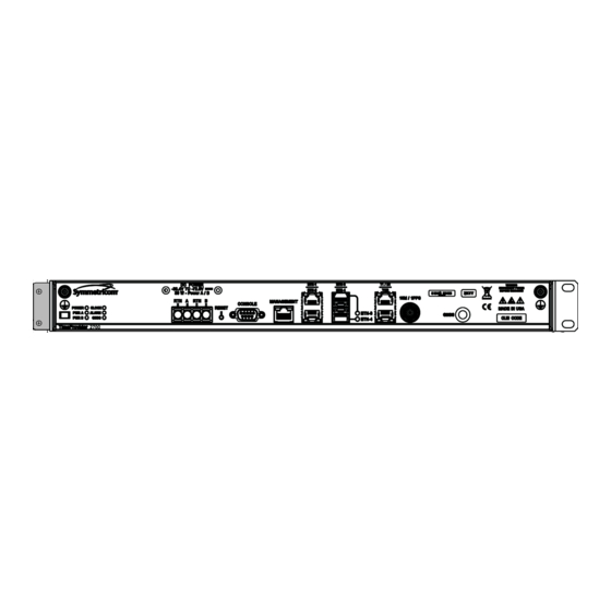
Page 27: Timeprovider 2700 Dc Version Connectors And Leds
DC version TimeProvider 2300/2700 showing connectors and LEDs. Figure 1-2 show the AC version. Figure 1-1. TimeProvider 2700 DC Version Connectors and LEDs Figure 1-2. TimeProvider 2700 AC Version Connectors and LEDs Figure 1-3. TimeProvider 2300 DC Version Connectors and LEDs Figure 1-4. -
Page 28: Serial Port Connector
Figure 1-5. Serial Port Connector Input Connections GNSS Connection The TimeProvider 2700 features an SMA connector for input from GPS or GLONASS navigation satellites to provide a frequency and time reference. GNSS is not available on the TImeProvider 2300. Figure 1-6. - Page 29 Chapter 1 Overview Physical Description PTP / SyncE Input Connections The TimeProvider 2300/2700 provides two possible PTP/SyncE input connections, labeled S1 and R1, although only one connection can be used at any time. The TimeProvider 2300/2700 features a single Ethernet 1000 Small-form Factor Pluggable (SFP) connection, labeled S1, for PTP/SyncE input (see Figure 1-7).
-
Page 30: T1/E1 Input Connection
Chapter 1 Overview Physical Description Figure 1-8. T1/E1 Input Connection Output Connections PTP / SyncE Output Connections The TimeProvider 2300/2700 provides two possible PTP/SyncE output connections, labeled S2 and R2, although only one connection can be used at any time. The TimeProvider 2300/2700 features a single Ethernet 1000 Small-form Factor Pluggable (SFP) connection (optical only), labeled S2, for PTP/SyncE output (see Figure... -
Page 31: T1/E1 & Tod Output Connections
Chapter 1 Overview Physical Description Figure 1-10. T1/E1 & TOD Output Connections TOD Output Port The TimeProvider 2300/2700 provides an RJ45 connector (Figure 1-10) with Time of Day (TOD) output. 10MHz & 1PPS Output Connections The TimeProvider 2300/2700 features a BNC male connector that is software configurable for either 10 MHz or 1PPS output. -
Page 32: Timeprovider 2300/2700 Dc Version Power And Ground
Chapter 1 Overview Functional Description Figure 1-12. TimeProvider 2300/2700 DC Version Power and Ground (TP 2700 shown) Figure 1-13. TimeProvider 2300/2700 AC Version Power and Ground (TP 2700 shown) Functional Description Figure 1-14 below for a representation of the functional architecture for the TimeProvider 2300/2700. -
Page 33: Functional Architecture
Chapter 1 Overview Functional Description Figure 1-14. Functional Architecture Note: The TP 2300 does not include a GNSS receiver. LEDs The TimeProvider 2300/2700 provides from three to six LEDs on the front panel, based on the specific model, that indicate the following: Power Status ... -
Page 34: Leds For Tp2700 - Dc Version
Chapter 1 Overview Functional Description Figure 1-15. LEDs for TP2700 - DC Version Figure 1-16. LEDs for TP2700 - AC Version Figure 1-17. LEDs for TP2300 - DC Version Figure 1-18. LEDs for TP2300 - AC Version Communication Ports Communication ports on the TimeProvider 2300/2700 allow you to provision, monitor, and troubleshoot the chassis. -
Page 35: Time Inputs
Functional Description Time Inputs The TimeProvider 2700 can use either GNSS, or PTP as external input references. The TimeProvider 2300 can use PTP. The PTP signal connects to an SFP (S1) or RJ45 (R1) connector on the front panel. The GNSS (GPS or GLONASS) reference connects to an SMA connector on the front panel of the TP 2700. -
Page 36: Configuration Management
Chapter 1 Overview Configuration Management Configuration Management The Command Line Interface (CLI), also called the ASCII command set, can be used to control the TimeProvider 2300/2700 from a terminal connected to the EIA-232 serial port, or the Ethernet MGMT port. Refer to Chapter 3, CLI Commands for further details. -
Page 37: Web Interface
Chapter 1 Overview Alarms Figure 1-19. Web Interface Alarms The TP 2300/2700 uses alarms to notify you when certain conditions are deteriorating below specified levels or when issues arise like loss of power or loss of connectivity. These alarms are indicated by status LEDs and by SNMP traps. You can provision the alarm to either be enabled or disabled and the current alarm state can be obtained via the communication ports. - Page 38 Chapter 1 Overview Alarms TimeProvider 2300/2700 User’s Guide 098-00564-000 Revision A3 – July, 2013...
-
Page 39: Chapter 2 Installing
Chapter 2 Installing This chapter describes the procedures for installing the TimeProvider 2300/2700. In This Chapter Getting Started Unpacking the Unit Rack Mounting the TimeProvider 2300/2700 Installation Check List Signal Connections – Communications Connections – TP 2300/2700 Synchronization and Timing Connections Connecting the GNSS Antenna ... -
Page 40: Getting Started
Before you begin to install the TimeProvider 2300/2700, review the information in this section. If you encounter any difficulties during the installation process, contact Symmetricom Global Services (SGS). See Contacting Technical Support, on page 272 for telephone numbers. Contact SGS - Product Technical Support for technical information. -
Page 41: Installation Tools And Equipment
Chapter 2 Installing Getting Started The DC version of the TimeProvider 2300/2700 is to be installed into a rack with permanent connection to the -48VDC mains. This connection is to be made to a branch over-current, short-circuit protection device with replaceable fusing of 1.5 amps, maximum. -
Page 42: Unpacking The Unit
1. Wear a properly grounded protective wrist strap or other ESD device. 2. Inspect the container for signs of damage. If the container appears to be damaged, notify both the carrier and your Symmetricom distributor. Retain the shipping container and packing material for the carrier to inspect. -
Page 43: Rack Mounting The Timeprovider 2300/2700
See Figure 2-1 for the location of the label on the TP 2300/2700. Contact your Symmetricom distributor if the model or item number do not match. For a complete listing of item numbers, see... -
Page 44: Dimensions For Timeprovider 2300/2700
Chapter 2 Installing Rack Mounting the TimeProvider 2300/2700 attached to the chassis at equal distances from the front of the unit (see Figure 2-4) using 6-32 x 1/4-inch screws. 2. Mount the chassis to the front of the equipment rack rails with four screws and associated hardware. -
Page 45: Making Ground And Power Connections
Chapter 2 Installing Making Ground and Power Connections Figure 2-4. Rack Mounting the TP 2300/2700 Making Ground and Power Connections Warning: To avoid accidental power-up of the chassis, remove the A and B fuses on the branch over-current protection unit before beginning installation of the DC version of the TP 2300/2700. -
Page 46: Ground Connections
2-9. These studs are located on the left and right sides of the front panel for the TP 2300/2700. Figure 2-5. TimeProvider 2700 Power & Ground Connections - DC Version Figure 2-6. TimeProvider 2700 Power & Ground Connections - AC Version Figure 2-7. -
Page 47: Universal Ground Symbol
Universal Ground Symbol If only one ground connection is to be used, Note: Symmetricom recommends connecting to the frame ground connection closest to the power connector (AC or DC). After installing the TimeProvider 2300/2700 into the rack, connect the chassis to the proper grounding zone or master ground bar. -
Page 48: Dc Power Connections
Chapter 2 Installing Making Ground and Power Connections DC Power Connections Use the following procedure to make the power connections for the DC version of the TimeProvider 2300/2700. Warning: To avoid possible damage to equipment, you must provide power source protective fusing as part of the installation. The TimeProvider 2300/2700 is intended for installation in a restricted-access location. - Page 49 Chapter 2 Installing Making Ground and Power Connections Testing DC Power Connections To verify that the power connections to the TimeProvider 2300/2700 are correct, follow the steps in this section. The primary DC power connections on the TP 2300/2700 are referred to as Power A and Return A. The secondary DC power connections are referred to as Power B and Return B.
-
Page 50: Ac Power Connection
Chapter 2 Installing Signal Connections AC Power Connection Use the following procedure to make the power connections for the AC version of the TimeProvider 2300/2700. An external Surge Protective Device is required to be used with the AC version of the TimeProvider 2300/2700. Figure 2-12. -
Page 51: Serial Port Male Mating Connector Pins
Chapter 2 Installing Signal Connections Table 2-1. System Management Ethernet Connector Pin Assignments 10Base-T 1000Base-T RJ-45 Pin 100Base-T Signal Signal TX+ (Transmit positive) BI_DA+ TX- (Transmit negative) BI_DA RX+ (Receive positive) BI_DB+ Not Used BI_DC+ Not Used BI_DC RX- (Receive negative) BI_DB... -
Page 52: Tp 2300/2700 Synchronization And Timing Connections
Ground TP 2300/2700 Synchronization and Timing Connections The TimeProvider 2700 has one GNSS input, one PTP timing input (license required), and one PTP timing output. The TimeProvider 2300 has one PTP timing input and one PTP timing output. The TimeProvider 2300/2700 also has one E1 or T1 output, one 10MHz or 1PPS output, and one TOD output. -
Page 53: Optical Sfp Transceiver
Transceiver Distance (max) Optical 1000 Base-LX Avago AFCT-5701PZ 10km on 9/125m Single-Mode Ethernet 1310nm Finisar FTLF1319P1BTL single-mode fiber (Symmetricom 121-20621-10-2) Optical 1000 Base-SX Avago AFBR-5710PZ 500m on 50/125m Multi-Mode Ethernet 850nm multi-mode fiber Finisar FTLF8519P2BNL (Symmetricom 121-20621-11-2) 275m on 62.5/125m multi-mode fiber 098-00564-000 Revision A3 –... -
Page 54: T1 / E1 And Tod Outputs Rj-45 Connection
Chapter 2 Installing Signal Connections Note: Recommended and supported SFP connectors comply with FDA radiation performance standards, 21 CFR Subchapter J. T1/E1 Connection The TimeProvider 2300/2700 features a single RJ-48C port for either a T1 or E1 output signal, as shown in Figure 2-16. -
Page 55: 1Pps+Tod Port Pin-Outs - Rj45 Connector
Chapter 2 Installing Signal Connections Table 2-4. T1/E1 Output Port Pin-Outs - RJ-48C Connector Signal TOD Connection The TimeProvider 2300/2700 features a RJ-45 port for the TOD output signal, as shown in Figure 2-16. See Table 2-5 for pin-outs for this RJ-45 connector. See Table for TOD default parameters. -
Page 56: Connecting The Gnss Antenna
Chapter 2 Installing Connecting the GNSS Antenna 1PPS/10MHz Connections Table 2-6. Default Parameters for TOD Information Transmission Default Comment Baud Rate 9600 Cannot be changed Parity Check None Start Bit 1 (low level) Stop Bit 1 (high level) Idle Frame High level Data Bits The TimeProvider 2300/2700 features a single BNC male port for the 10 MHz or... -
Page 57: Installation Check List
Chapter 2 Installing Installation Check List Proper cable, grounding techniques, and lightning arrestors should be used. Mount the antenna outside, preferably on the roof with an unobstructed view of the sky. Do not mount the antenna near a wall or other obstruction blocking part of the sky. Mount the antenna well above roads or parking lots. -
Page 58: Normal Power Up Indications
Chapter 2 Installing Applying Power to the TimeProvider 2300/2700 Normal Power Up Indications As the TimeProvider 2300/2700 powers up and begins normal operation, the LEDs all turn on. After the self-test is complete and the firmware is operational, the LED states may change to indicate the appropriate state or status. - Page 59 Chapter 2 Installing Applying Power to the TimeProvider 2300/2700 Table 2-8. LED Descriptions (Continued) Label Description ETH1 - R1 Ethernet Port 1 - RJ45 (r1) Left Amber Flashing - Activity on link for 100M LEDs on the Ethernet connector Left Amber On - Link established for 100M Left Amber Off - No link for 100M Right Green Flashing- Activity on link for 1000M Right Green On - Link established for 1000M...
- Page 60 Chapter 2 Installing Applying Power to the TimeProvider 2300/2700 TimeProvider 2300/2700 User’s Guide 098-00564-000 Revision A3 – July, 2013...
-
Page 61: Chapter 3 Cli Commands
Chapter 3 CLI Commands This chapter describes the CLI command conventions, the prompts, line editing functions, and command syntax. The CLI command functions and features are organized by user security access levels and are listed alphabetically. In This Appendix CLI Overview ... -
Page 62: Cli Overview
Chapter 3 CLI Overview CLI Overview The Command Line Interface (CLI), also called the ASCII command set, can be used to control the TimeProvider 2300/2700 from a terminal connected to the EIA-232 serial port, or the Ethernet port. TimeProvider 2300/2700 CLI Command Conventions The following are conventions used for the TimeProvider 2300/2700 CLI command set. -
Page 63: Command Line Format
Chapter 3 CLI Overview In the following example, if you press the TAB key, or the ? (SHIFT+QUESTION MARK), after typing s, the CLI commands set, set-timeout, show, and sync display. Typing s at the prompt: TP2700> s Then pressing the TAB key : set-timeout show sync... -
Page 64: Command User Levels
Chapter 3 TimeProvider 2300/2700 CLI Command Set Command User Levels The TimeProvider 2300/2700 provides a hierarchy of CLI command user levels that permit an increasing level of access to system parameters. This allows the system administrator to add users who can only view but not change system parameters and users who can view and change system parameters. - Page 65 Chapter 3 TimeProvider 2300/2700 CLI Command Set ------------------------------------------------------------------- |ID |Date-Time |Descriptions |---|-------------------|-----------------------------------------| |2013-05-09 17:53:26|Entered time normal-track state |...|....|.........| |2013-05-09 17:53:26|Entered frequency normal-track state ------------------------------------------------------------------- Remarks: The information displayed is expected to be identical to an entry in the Event/Alarm Log File. Level : User, Config, and Admin 098-00564-000 Revision A3 –...
-
Page 66: Show Alarm-Config
Chapter 3 TimeProvider 2300/2700 CLI Command Set show alarm-config Displays the alarm configuration including alarm ID, severity, state, reporting delay and description for the TP 2300/2700 alarms. This also displays if the alarm is transitory. Command Syntax: show alarm-config Example: TP2700>... - Page 67 Chapter 3 TimeProvider 2300/2700 CLI Command Set |..|..|..|..|..........| |event |enable |0 |"SYNCE/T1E1 input SSM changed" |..|..|..|..|..........| |minor |enable |0 |"Incompatible transport type" |..|..|..|..|..........| |minor |enable |0 |"PTP input lost" |..|..|..|..|..........| |event |enable |0 |"PTP master switched" |..|..|..|..|..........| |event |enable |0 |"PTP time/frequency input not traceable"...
-
Page 68: Set Alarm-Config
Chapter 3 TimeProvider 2300/2700 CLI Command Set |137 |critical|enable |0 |"PLL synthesizer unlock" |..|..|..|..|..........| |138 |critical|enable |0 |"Rubidium unlock" |..|..|..|..|..........| |139 |event |enable |0 |"Temperature out of range" |..|..|..|..|..........| |151 |critical|enable |0 |"Production configuration data error" |..|..|..|..|..........| |152 |event |enable |0 |"Timeline has been changed"... - Page 69 Chapter 3 TimeProvider 2300/2700 CLI Command Set 2 - Critical 3 - Major 4 - Minor 5 - Event To provision the reporting delay of the specified Alarm number in seconds: set alarm-config delay {alarm [0 to 300] | all}[0 to 500000] Note: Use “show alarm-config”...
-
Page 70: Alias
Chapter 3 TimeProvider 2300/2700 CLI Command Set alias This command is used to assign an alias for a CLI command (or any character string). The alias can then be used as a convenient substitution for the CLI command to which it has been assigned. The alias command can also be used to display all defined aliases and the commands to which they have been assigned. - Page 71 Chapter 3 TimeProvider 2300/2700 CLI Command Set alias abc='show ip status mgmt' Level : User, Config, and Admin 098-00564-000 Revision A3 – July, 2013 TimeProvider 2300/2700 User’s Guide...
-
Page 72: Show Bridge-Time
Chapter 3 TimeProvider 2300/2700 CLI Command Set show bridge-time Displays the bridging time that is used to allow the frequency servo to coast through short periods when the system does not have qualified reference. The bridging time is in seconds. Command Syntax: show bridge-time Example:... -
Page 73: Show Clock
Chapter 3 TimeProvider 2300/2700 CLI Command Set show clock Displays the system date, time, and leapseconds in several formats. – Current system date and time – Accumulated leapseconds between TAI and UTC time – Pending leapseconds Command Syntax: show clock Example: TP2700>... - Page 74 Chapter 3 TimeProvider 2300/2700 CLI Command Set set clock date-time <date-time> Enter date and time in YYYY-MM-DD,HH:MM:SS format (UTC) To set the Accumulated leapseconds: set clock leapseconds <value> Note: If your GNSS is in GLONASS tracking mode, this command also provides the user-provisioned leap second to GPS-GLONASS.
-
Page 75: Set Configuration
Chapter 3 TimeProvider 2300/2700 CLI Command Set set configuration Use this command to backup the current configuration, restore the current configuration from a backup copy, or set the current configuration to factory default values. Command Syntax: To set the current configuration to factory or default values: ... -
Page 76: Show Eia-232
Chapter 3 TimeProvider 2300/2700 CLI Command Set show eia-232 This command displays the serial port’s operating parameters: baud rate, parity, word length, and stop bits. Command Syntax: show eia-232 Example: TP2700> show eia-232 Response: Baud rate : 57600 Data length Stop bit Parity Flow control... -
Page 77: Show Ethernet
Chapter 3 TimeProvider 2300/2700 CLI Command Set show ethernet The show ethernet command displays the packet service ports auto-negotiation state and speed for all Ethernet service ports. Command Syntax: show ethernet { config | status } Example 1: TP2700> show ethernet config Response 1a: ----------------------------------------------------------- Port... -
Page 78: Set Ethernet
Chapter 3 TimeProvider 2300/2700 CLI Command Set Level : User, Config, and Admin set ethernet Use this command to configure the Ethernet ports: the port state, the connector type, the auto-negotiation state and speed, and the Ethernet signal type. When Ethernet auto-negotiation is enabled, the TP 2300/2700 will advertise connection speeds of 100M, 1000M, or 100/1000M. - Page 79 Chapter 3 TimeProvider 2300/2700 CLI Command Set TP2700>set ethernet active-connector eth2 r2-rj45 Level : Config and Admin 098-00564-000 Revision A3 – July, 2013 TimeProvider 2300/2700 User’s Guide...
-
Page 80: Show Firewall
Chapter 3 TimeProvider 2300/2700 CLI Command Set show firewall This command displays the firewall configuration. Command Syntax: show firewall Example: TP2700> show firewall Response: TELNET Firewall : allow SSH Firewall : allow FTP Firewall : block ICMP Firewall : allow SNMP Firewall : allow HTTPS Firewall... -
Page 81: Show Gnss
Chapter 3 TimeProvider 2300/2700 CLI Command Set show gnss This command displays the GNSS port state, position (latitude, longitude, height), elevation mask value (positioning filter), mode of operation (manual or automatic), and track-mode selection, GPS or GLONASS, or GPS+GLONASS. It also displays information for all satellite vehicles being tracked: vehicle number, health, noise ratio, satellite elevation, satellite azimuth. - Page 82 Chapter 3 TimeProvider 2300/2700 CLI Command Set Current Status : ok Current Position Status : positionHold Current Antenna Position: Latitude : N37:22:42.98 Longitude : W121:55:34.87 Height : 14.40 Current GNSS Satellite View: ------------------------------------------------------------- |Index | No |SNR | Health | Azimuth |Elevation| Sat Type | |------|-----|----|----------|---------|---------|----------| | healthy | glonass...
-
Page 83: Set Gnss
Height is in meters with one digit after the decimal point, for example: 17.5 Note: Symmetricom recommends that the Auto mode be used. Any error in the manually-specified system position will generate timing errors. To set the GNSS mask value ... - Page 84 Chapter 3 TimeProvider 2300/2700 CLI Command Set To set the GNSS cable-delay value set gnss cable-delay <delay-value> Table B-25 for cable delay values. The delay values shown correspond to the cable kit being used in its entirety without modification. The values assume that a splitter is not used.
-
Page 85: Show Hardware-Status
Chapter 3 TimeProvider 2300/2700 CLI Command Set show hardware-status This command displays the status of the specified hardware. Command Syntax: show hardware-status Example: TP2700> show hardware-status Response: -48V-A ok (DC only) -48V-B ok (DC only) +1.2V 1.211V +3.3V 1.830V +2.5V 2.513V +5.0V 5.016V... -
Page 86: History
Chapter 3 TimeProvider 2300/2700 CLI Command Set history This command shows the command history for the current session. Command Syntax: history Example: tp2700> history Response: 0 2013-06-10 00:11:28 show eth-status 1 2013-06-10 00:12:24 show event 2 2013-06-10 00:13:15 show firewall 3 2013-06-10 00:16:02 set firewall ssh 4 2013-06-10 00:16:31 generate message 5 2013-06-10 00:17:07 show gnss... -
Page 87: Show Hostname
Chapter 3 TimeProvider 2300/2700 CLI Command Set show hostname This command displays the host name for the TimeProvider 2300/2700. Command Syntax: show hostname Example: tp2700> show hostname Response: Host name : Timeprovider Level : User, Config, and Admin set hostname This command sets the host name for the TimeProvider 2300/2700. -
Page 88: Show Image
Chapter 3 TimeProvider 2300/2700 CLI Command Set show image This command displays the firmware image and the firmware version in the system. The backup image is the non-active image. Command Syntax: show image Example: tp2700> show image Response: SYSTEM IMAGE DETAILS Active image 1.0.3 Backup image... - Page 89 Chapter 3 TimeProvider 2300/2700 CLI Command Set To set the system to boot from image 1: TP2700> set image 1 Example 2: To set the system to boot from image 2: TP2700> set image 2 Remark: The system must be rebooted to implement the boot image. Level : Config and Admin 098-00564-000 Revision A3 –...
-
Page 90: Show Input
Chapter 3 TimeProvider 2300/2700 CLI Command Set show input This command displays the current configuration or status for input signals for the T1/E1 port. The values displayed with this command will be applied to the T1/E1 port only when the IO-direction of the port is configured as an Input with the command. -
Page 91: Set Input
Chapter 3 TimeProvider 2300/2700 CLI Command Set Port config ---------------------------------------------- Port State Io dir | Signal/format| |--------|---------|----------|--------------| t1e1 enable | output |..|..|..|....| Example 2: TP2700> show input status t1e1 Response 2a: ------------------------------------------------------------------------------ |Port |input status|ssm |los |ais |oof |bpv |crc |---------|------------|--------|--------|--------|--------|--------|--------| |t1 input |fault |fault... - Page 92 Chapter 3 TimeProvider 2300/2700 CLI Command Set – CCS, CAS, or freq 2048KHz for E1 – D4, ESF, or freq 1544KHz for T1 CRC state for E1 SSM Bit position for E1 All the configurations provisioned by this command apply to the T1/E1 input port only when the IO-direction of the port is configured as an Input with the command.
- Page 93 Chapter 3 TimeProvider 2300/2700 CLI Command Set – SSM state is configured by command. set ref – No CRC required for framing types of D4, freq2048khz, and freq1544khz. – No user provisioning CRC for ESF. It is hardcoded as ENABLE. Level : Config and Admin 098-00564-000 Revision A3 –...
-
Page 94: Show Inventory
Chapter 3 TimeProvider 2300/2700 CLI Command Set show inventory This command displays the following inventory information of the systems. Description of the product Part number CLEI number Serial number Software version Hardware version GNSS Device ID, Device type and firmware revision ... -
Page 95: Set Inventory
Chapter 3 TimeProvider 2300/2700 CLI Command Set set inventory Use this command to provision the system's user-assigned asset value information. Command Syntax: set inventory asset <asset-value> Example: To set the inventory asset to a value of "tcb121" set inventory asset tcb121 Level : Config and Admin 098-00564-000 Revision A3 –... -
Page 96: Show Ip
Chapter 3 TimeProvider 2300/2700 CLI Command Set show ip This command displays the Host, Mask, and Gateway IP addresses for Ethernet interfaces. It also indicates if DHCP is enabled and if the port is enabled. Command Syntax: To show the configuration of the Ethernet interface (some settings will only be ... -
Page 97: Set Ip
Chapter 3 TimeProvider 2300/2700 CLI Command Set Static mode Parameters IP address 192.168.9.44 IP mask 255.255.255.0 IP gateway 0.0.0.0 Example 3: To display the status of the Ethernet interfaces for the Ethernet management port: tp2700> show ip status mgmt Response 3: mgmt0 Link encap:Ethernet HWaddr 00:B0:AE:00:00:05 inet addr:192.168.5.14 Bcast:192.168.5.255 Mask:255.255.255.0 UP BROADCAST RUNNING MULTICAST MTU:1500 Metric:1... - Page 98 Chapter 3 TimeProvider 2300/2700 CLI Command Set The IP addresses for the MGMT, ETH1 and ETH2 ports must be on different networks/subnets. set vlan Note: To configure a VLAN, use the command to provision the IP addresses. The special value of 0.0.0.0 should be used for the gateway value if a gateway router is not required.
- Page 99 Chapter 3 TimeProvider 2300/2700 CLI Command Set To set the IPv4 address for the Ethernet management packet service port ETH1 to 192.168.2.11, the mask to 255.255.255.0, and the gateway 0.0.0.0: tp2700> set ip ip-address eth1 ipv4 address 192.168.2.11 netmask 255.255.255.0 gateway 0.0.0.0 tp2700>...
-
Page 100: Show Led
Chapter 3 TimeProvider 2300/2700 CLI Command Set show led This command displays the LED status for each LED on the front panel. See Table for LED descriptions. Command Syntax: show led Example 1: TP2700> show led Response 1: ------------------------------ |LED ID |LED Status |------------|---------------| |power... -
Page 101: Show License
| PTP Master functionality |..|......|..........| Level : User, Config, and Admin Note: A license key is required to enable licensed features. Please contact your local sales representative or Symmetricom Technical Support at 1-888-367-7966 (USA) or 1-408-428-7907 for additional information. set license Use this command to enter the 40-character license key for new features, and to delete features. - Page 102 Chapter 3 TimeProvider 2300/2700 CLI Command Set Command Syntax: To enter a license key for new features: set license add The TP 2300/2700 will prompt for the license key and the user needs to enter the 40-character key string. To remove an installed feature license: ...
- Page 103 Chapter 3 TimeProvider 2300/2700 CLI Command Set ptp-input - Precision Time Protocol Input t1-e1 - TDM (T1/E1) with Input and Output ptp-client-capacity-64 - PTP Master with max capacity of 64 clients syncE - Synchronous Ethernet Input and Output ptp-master - PTP Master functionality Enter License Feature to be deleted: Select the feature to be deleted from the list and press Enter.
-
Page 104: Show Log
Chapter 3 TimeProvider 2300/2700 CLI Command Set show log This command displays the specified log file from the local storage. When showing the log content, the Index parameter selects one of the seven rotated log files. The Head parameter, along with the count value, displays the specified number of events from the beginning of the file. - Page 105 Chapter 3 TimeProvider 2300/2700 CLI Command Set To display the last 10 entries of the alarm-event log (10 lines from the tail of current log): TP2700> show log alarm-event tail 10 Response 2: 2012-12-29 00:00:10 TIMEPROVIDER alarmid: 006,000,EVENT, time Entered bridging state 2012-12-29 00:00:34 TIMEPROVIDER alarmid: 006,000,EVENT, freq Entered bridging state 2012-12-29 00:22:06 TIMEPROVIDER alarmid: 010,000,EVENT,...
-
Page 106: Show Log-Config
Use this command to provision the specified log file buffer size, the maximum number of kilobytes to be stored in the file before it is rotated, and to configure a remote syslog server to receive log messages from the TimeProvider 2700. Command Syntax: To configure the size of the log: ... - Page 107 Chapter 3 TimeProvider 2300/2700 CLI Command Set set log-config size {alarm-event | command | security} <size-value> To enable or disable the remote-syslog: set log-config remote-syslog {enable | disable} Example 1: To set the size of the alarm-event log to 100 kilobytes: TP2700>...
-
Page 108: Logout
Chapter 3 TimeProvider 2300/2700 CLI Command Set logout This command terminates the current user connection. Command Syntax: logout Example: TP2700> logout Level : User, Config, and Admin 108 TimeProvider 2300/2700 User’s Guide 098-00564-000 Revision A3 – July, 2013... -
Page 109: Show Output
Chapter 3 TimeProvider 2300/2700 CLI Command Set show output This command displays the current configuration or status for output signals for the T1/E1 port and the PPS offset on the PPS/10M output port. The provisioning displayed with the command will apply to the T1/E1 show output config t1e1 port only when the IO-direction of the port is configured as OUTPUT with the command. - Page 110 Chapter 3 TimeProvider 2300/2700 CLI Command Set -------------------------------------------------------------- |Signal |FrameType |CRC |SSMBit |zero suppression| |------------|------------|--------|--------|----------------| |e1 output |ccs |enable |all |off |....|....|..|..|....| |t1 output |esf -------------------------------------------------------------- Port Config -------------------------------------------------------- |Port |state |io dir |Signal /Format | |------------|------------|------------|---------------| |t1e1 |enable |output -------------------------------------------------------- Example 2:‘...
-
Page 111: Set Output
Chapter 3 TimeProvider 2300/2700 CLI Command Set Port config --------------------------------------- Port state Signal/format | |---------|----------|----------------| | pps10m enable 10MHz |..|..|....| Example 3: TP2700> show output status t1e1 Response 3a: --------------------------- |io status |port status | |------------|------------| |t1 output --------------------------- Response 3b: ---------------------------| | io status | port status |... - Page 112 Chapter 3 TimeProvider 2300/2700 CLI Command Set SSM Bit position for E1 Zero-Suppression (On or Off) for E1 All the configurations provisioned by this command apply to the T1/E1 port only when the IO-direction of the port is configured as an Output with the command.
- Page 113 Chapter 3 TimeProvider 2300/2700 CLI Command Set TP2700> set output e1 ssmbit t1e1 6 Example 4: To provision the frame type of the T1 output signal that might apply to T1/E1 port as TP2700> set output t1 frametype t1e1 d4 Level : Config and Admin 098-00564-000 Revision A3 –...
-
Page 114: Show Output-Gen
Chapter 3 TimeProvider 2300/2700 CLI Command Set show output-gen This command displays the configuration for Output Port behavior during the warm-up, free-run, fast-track and holdover states. Command Syntax: show output-gen Example: TP2700> show output-gen Response: Output generation configuration: -------------------------------------------------------------- |Port |warm-up |free-run |holdover... - Page 115 Chapter 3 TimeProvider 2300/2700 CLI Command Set Example 2: To provision the output behavior to ON during the holdover state for the TOD output port: TP2700> set output-gen holdover tod on Level : Config and Admin 098-00564-000 Revision A3 – July, 2013 TimeProvider 2300/2700 User’s Guide 115...
-
Page 116: Password
Level : User, Config, and Admin Note: Be sure to not lose or forget the password. Contact Symmetricom support for the password recovery procedure if all admin-level user passwords are lost. 116 TimeProvider 2300/2700 User’s Guide 098-00564-000 Revision A3 – July, 2013... -
Page 117: Ping
Chapter 3 TimeProvider 2300/2700 CLI Command Set ping Use this command to ping the host specified by the address (xxx.xxx.xxx.xxx) and display ping statistics from Ethernet maintenance port or PTP service port. To minimize system resource usage and deter denial of Note: service attacks, the system is configured to allow a maximum ICMP ping request rate of 1 per second. -
Page 118: Show Port-Control
Chapter 3 TimeProvider 2300/2700 CLI Command Set show port-control This command provisions the sync service port, legacy port, or packet time service ports configurations. Command Syntax: show port-control Example 1: TP2700>show port-control Response 1: -------------------------------------------- |Port |State |IO dir |Signal/Format| |---|-------|--------|-------|-------------| |t1e1 |enable... - Page 119 Chapter 3 TimeProvider 2300/2700 CLI Command Set To provision the signal type for the T1/E1 port: set port-control t1e1 signal-type {e1 | t1} To provision the port state for the PPS/10M port: set port-control pps10m state {enable | disable} To provision the signal type for the PPS/10M port: ...
-
Page 120: Show Pql-Ssm
Chapter 3 TimeProvider 2300/2700 CLI Command Set show pql-ssm This command displays the Priority Quality Level (PQL) values for reference input signal types. The PQL corresponds to the “ssm-value” parameter that is used with the “set ref” command for reference selection. The PQL is a representation of traceability for the signal presented at the input ports, where a PQL value of 16 represents an invalid SSM. - Page 121 Chapter 3 TimeProvider 2300/2700 CLI Command Set |10 |0x8 |0x8 |QL_SSU_B/G.812 Type VI |...|..|..|..|..|........| |11 |0x8 |0x8 |100 |QL_SSU_B/G.812 Type VI |...|..|..|..|..|........| |12 |0xB |0xB |102 |QL-SEC/EEC1/G.813 Opt1,G.8264 |...|..|..|..|..|........| |13 |0xB |0xB |104 |QL-SEC/EEC1/G.813 Opt1,G.8264 |...|..|..|..|..|........| |14 |0xF |0xF |106 |248 |QL-SEC/EEC1/G.813 Opt1,G.8264 |...|..|..|..|..|........|...
- Page 122 Chapter 3 TimeProvider 2300/2700 CLI Command Set Item 2 in Option I Table: For E1 or SycnE input with received SSM = 0x00, PQL = 2. For E1 or SycnE output with the system PQL = 2, SSM = 0x02. Related :SSM during bridging will be the last SSM value of input reference while clock was in normal lock state.
-
Page 123: Show Ptp
Chapter 3 TimeProvider 2300/2700 CLI Command Set show ptp Use this command to display the PTP master and PTP client configuration information: the active profile selection, and all the parameters under different profiles, the client list for PTP master, the grand master table for PTP client, and the status for PTP master and PTP client. - Page 124 Chapter 3 TimeProvider 2300/2700 CLI Command Set To display the asymmetry state for PTP client on the ETH1 port: show ptp client config eth1 asymmetry state To display detailed configurable attributes for PTP client on the ETH1 port: show ptp client config eth1 telecom-2008 Example 1: To show info for PTP client with known clock ID 00:B0:AE:FF:FE:01:1A:85 for PTP...
- Page 125 Chapter 3 TimeProvider 2300/2700 CLI Command Set Response 3b: ETH2 PTP MASTER ACTIVE-PROFILE: itu-g8265-1 Response 3c: ETH2 PTP MASTER ACTIVE-PROFILE: default Example 4 To show the PTP client active-profile: TP2700>show ptp client active-profile eth1 Response 4: ETH1 PTP CLIENT ACTIVE-PROFILE: telecom-2008 ...
- Page 126 Chapter 3 TimeProvider 2300/2700 CLI Command Set TP2700>show ptp master config eth2 itu-g8265-1 Response 6: EHT2 PTP MASTER CONFIGURATION WITH PROFILE ITU-G8265-1: PTP State : enable PTP TTL : 64 PTP DSCP PTP Dither : disable PTP Max Number Clients : 256 PTP Two Steps : disable...
- Page 127 Chapter 3 TimeProvider 2300/2700 CLI Command Set Example 8: To show the status of PTP master on ETH2 port: TP2700>show ptp master status eth2 Response 8: ETH2 PTP MASTER STATUS Port enabled : yes Clock Id : 00:b0:ae:ff:fe:03:46:69 Port Number Profile : telecom-2008 Port state...
- Page 128 Chapter 3 TimeProvider 2300/2700 CLI Command Set ------------------------------ |Index |address |-------|--------------------| |192.168.9.41 |..|....| |0.0.0.0 ------------------------------ Example 10: To show the status for PTP clients on ETH1 port: TP2700>show ptp client status eth1 Response 10: ETH1 PTP CLIENT STATUS: Client Status : OK Minimal Round Trip Delay(us) : 0.74...
-
Page 129: Ptp Client Status Descriptions
Chapter 3 TimeProvider 2300/2700 CLI Command Set Table 3-1. PTP Client Status Descriptions Status Parameter Description Client Status Indicates whether the client has established flow with the master. Minimal Round Trip Delay (µs) Indicates the smallest round trip delay between this slave port and its upstream master. - Page 130 Chapter 3 TimeProvider 2300/2700 CLI Command Set Table 3-1. PTP Client Status Descriptions Status Parameter Description Mode width (ns) Current estimate of the main mode width of the forward packet delay variation. The mode width is used in both weighting and compensation. Mode width is a good indicator of loading.
- Page 131 Chapter 3 TimeProvider 2300/2700 CLI Command Set Response 12: ETH1 PTP client port transport type : Ethernet Example 13: To display the configuration of the service tier for PTP client on ETH1 port: TP2700> show ptp client config eth1 service-tier Response 13: ETH1 PTP client port service-tier : sync-mask...
-
Page 132: Set Ptp
Chapter 3 TimeProvider 2300/2700 CLI Command Set set ptp The command is used to provision the configurable parameters for PTP output (master) and PTP input (client), including the profile selection, the attributes under different profiles, and to provision the Grand Master table for PTP client. Table 3-2. - Page 133 Chapter 3 TimeProvider 2300/2700 CLI Command Set – If the timescale is set to “auto”, the TP 2300/2700 will make the decision based on the input. The TP 2300/2700 will set the timescale to “ptp” if the unit is locked to GNSS or PTP. The TP 2300/2700 will set the timescale to “arb”...
- Page 134 Chapter 3 TimeProvider 2300/2700 CLI Command Set To provision the sync-interval value for a Master with the Default (multicast) active profile: set ptp master config eth2 default sync-interval <sync-interval-value> To provision the client-timeout value for a Master with the Default (multicast) ...
- Page 135 Chapter 3 TimeProvider 2300/2700 CLI Command Set To provision the PTP priority-2 value for the Master with the Telecom-2008 (unicast) active profile: set ptp master config eth2 telecom-2008 priority-2 <priority-2-value> To provision the PTP domain value for the Master with the Telecom-2008 ...
- Page 136 Chapter 3 TimeProvider 2300/2700 CLI Command Set To provision the delay limit, the minimum interval (maximum rate) between PTP delay response messages, for the Master with the Telecom-2008 (unicast) active profile: set ptp master config eth2 telecom-2008 delay-limit <delay-limit-value> –...
- Page 137 Chapter 3 TimeProvider 2300/2700 CLI Command Set To provision the PTP domain value for the Master with the ITU-G.8265-1 (unicast) active profile: set ptp master config eth2 itu-g8265-1 domain <domain-value> To provision the PTP Diffserv Code Point value for the Master with the ...
- Page 138 Chapter 3 TimeProvider 2300/2700 CLI Command Set set ptp master config eth2 itu-g8265-1 delay-limit <delay-limit-value> – The interval is 2 seconds, where z= <delay-limit-value>. PTP CLIENT: To provision the active profile for PTP client: set ptp client active-profile eth1 telecom-2008 To provision a VLAN for a master in the acceptable master table for PTP client: ...
- Page 139 Chapter 3 TimeProvider 2300/2700 CLI Command Set To provision the acceptable master table for PTP client: set ptp client config eth1 telecom2008 master-table add index {1 | 2} address < ipv4-address> All master IP addresses configured in the master table Note: must be reachable, either by being in the same subnet as the port (ETH1) IP address, or through a configured gateway.
- Page 140 Chapter 3 TimeProvider 2300/2700 CLI Command Set Table 3-3. PTP Master Default Profile (Multicast) Parameter Descriptions Parameter Description Use to enable the grandmaster for two-step clock two-step mode on the specified port. If two-step clock mode is disabled, the grandmaster uses one-step clock mode. Use to select the timescale for the selected port.
- Page 141 Chapter 3 TimeProvider 2300/2700 CLI Command Set Table 3-3. PTP Master Default Profile (Multicast) Parameter Descriptions (Continued) Parameter Description dscp The Differentiated Services Code Point is an 6-bit field in the 8-bit Differentiated Services (DS) field of the IP packet header to specify what classes of traffic will be provided, what guarantees are needed for each class, and how much data will be sent for each class.
- Page 142 Chapter 3 TimeProvider 2300/2700 CLI Command Set Table 3-4. PTP Master Telecom-2008 & ITU-G8265-1 Profiles (Unicast) Parameter Descriptions Parameter Description Use to enable the grandmaster for two-step clock mode on two-step the specified port. If two-step clock mode is disabled, the grandmaster uses one-step clock mode.
- Page 143 Chapter 3 TimeProvider 2300/2700 CLI Command Set Table 3-4. PTP Master Telecom-2008 & ITU-G8265-1 Profiles (Unicast) Parameter Descriptions Parameter Description dscp The Differentiated Services Code Point is an 6-bit field in the 8-bit Differentiated Services (DS) field of the IP packet header to specify what classes of traffic will be provided, what guarantees are needed for each class, and how much data will be sent for each class.
- Page 144 Chapter 3 TimeProvider 2300/2700 CLI Command Set Table 3-5. PTP Client Parameter Descriptions for Telecom-2008 Profile Parameter Description transport Network (PTP packet delivery): Ethernet service-tier PTP sync service tier applies to PTP client and is defined by a performance mask which is used to monitor performance.
- Page 145 Chapter 3 TimeProvider 2300/2700 CLI Command Set Table 3-5. PTP Client Parameter Descriptions for Telecom-2008 Profile (Continued) Parameter Description domain Sets the domain value for the Client clock. IEEE-1588-2008 defines a domain as a logical grouping of clocks that synchronize to each other using the protocol, but that are not necessarily synchronized to clocks in another domain.
- Page 146 Chapter 3 TimeProvider 2300/2700 CLI Command Set delay-limit priority-1 priority-2 domain timescale Refer to Table B-39, Table B-40, and Table B-41 in Appendix B for range and default values for PTP parameters. TP2700>set ptp master config eth2 telecom-2008 ptp-state enable TP2700>set ptp master config eth2 telecom-2008 ttl 100 TP2700>set ptp master config eth2 telecom-2008 dscp 5 TP2700>set ptp master config eth2 telecom-2008 dither enable...
- Page 147 Chapter 3 TimeProvider 2300/2700 CLI Command Set To provision the following attributes of profile itu-g8265-1 for PTP master in eth2 port: ptp-state dscp dither two-step unicast-negotiation lease-limit announce-limit sync-limit delay-limit priority-1 ...
- Page 148 Chapter 3 TimeProvider 2300/2700 CLI Command Set TP2700>set ptp master config eth2 itu-g8265-1 domain 0 TP2700>set ptp master config eth2 itu-g8265-1 timescale auto Example 5: To set the active-profile of PTP master on ETH2 port as default: TP2700>set ptp master active-profile eth2 default Example 6: To provision the following attributes of profile default for PTP master in eth2 port: ptp-state...
- Page 149 Chapter 3 TimeProvider 2300/2700 CLI Command Set TP2700>set ptp master config eth2 default priority-1 200 TP2700>set ptp master config eth2 default priority-2 200 TP2700>set ptp master config eth2 default domain 10 TP2700>set ptp master config eth2 default timescale auto TP2700>set ptp master config eth2 default announce-interval 2 TP2700>set ptp master config eth2 default sync-interval -6 TP2700>set ptp master config eth2 default announce-receipt-timeout 4 TP2700>set ptp master config eth2 default client-timeout 100...
- Page 150 Chapter 3 TimeProvider 2300/2700 CLI Command Set TP2700>set ptp client config eth1 telecom-2008 ttl 10 TP2700>set ptp client config eth1 telecom-2008 dscp 8 TP2700>set ptp client config eth1 telecom-2008 unicast-negotiation enable TP2700>set ptp client config eth1 telecom-2008 lease-duration 300 TP2700>set ptp client config eth1 telecom-2008 announce-interval -4 TP2700>set ptp client config eth1 telecom-2008 announce-receipt-timeout TP2700>set ptp client config eth1 telecom-2008 sync-interval -7 TP2700>set ptp client config eth1 telecom-2008 delay-req-interval -7...
-
Page 151: Reboot System
Command Syntax: reboot system Remarks: Example 1: TP2700> reboot system Response 1: The system is going down for REBOOT NOW! ........Symmetricom TimeProvider: login: TP2700> Level : Admin 098-00564-000 Revision A3 – July, 2013 TimeProvider 2300/2700 User’s Guide 151... -
Page 152: Show Ref
Chapter 3 TimeProvider 2300/2700 CLI Command Set show ref Use this command to display the configuration for reference selection including reference selection criteria, input priorities and configured PQL values, switching mode, and the reference status. Command Syntax: show ref config show ref status Example 1: TP2700>... -
Page 153: Set Ref
Chapter 3 TimeProvider 2300/2700 CLI Command Set TP2700> show ref status Response 2: Time Reference Status ------------------------------------ |Reference |final-pql|status |----------|---------|-------------| |GNSS |disqualified | |..|..|.....| |PTP |selected ------------------------------------ Frequency Reference Status ------------------------------------ |Reference |final-pql|status |----------|---------|-------------| |GNSS |disqualified | |..|..|.....| |PTP |selected |..|..|.....| |SYNCE |qualified... - Page 154 Chapter 3 TimeProvider 2300/2700 CLI Command Set To set the priority for a frequency reference input: set ref frequency priority {gnss | ptp |synce | t1e1} {1 - 10} To set the config-PQL value for a frequency reference input: ...
- Page 155 Chapter 3 TimeProvider 2300/2700 CLI Command Set To set the config-PQL value to 4 for a GNSS time reference input: set ref time config-pql gnss 4 Example 3: To set the priority value to 6 for a SyncE frequency reference input: set ref frequency priority synce 6 Example 4: To set the config-PQL value to 5 for a T1/E1 frequency reference input:...
-
Page 156: Show-Session-Timeout
Chapter 3 TimeProvider 2300/2700 CLI Command Set show-session-timeout For current opened user interface session, this command displays the inactivity timeout to the defined time interval, in seconds. 0 means the time-out for this session is disabled. Command Syntax: To display the session timeout: ... -
Page 157: Show Snmp
Chapter 3 TimeProvider 2300/2700 CLI Command Set show snmp Use these commands to display the SNMP Manager assigned to the agent, all assigned users (username only), and the SNMP trap version and SNMP trap user. Command Syntax: To display the SNMP manager assignment: ... - Page 158 Chapter 3 TimeProvider 2300/2700 CLI Command Set -------------------------------------------------------------------------- |Index|User Name |User Type |Auth. Key |Priv. Key |-----|--------------------|-------------|---------------|---------------| |test |snmpnoauth |********** |********** |..|....|.....|....|....| |harsha |snmpshades |********** |********** -------------------------------------------------------------------------- Example 3: TP2700> show snmp trapuser Response 3: No SNMP trap user configured. Example 4: TP2700>...
-
Page 159: Set Snmp
Chapter 3 TimeProvider 2300/2700 CLI Command Set set snmp Use this command to provision the SNMP v2 state, trap version, user assignment, manager assignment, and trapuser and v2 community assignments. Role Max Number SNMP User Trapuser Manager v2 Community Command Syntax: To add an SNMP user or trapuser: ... - Page 160 Chapter 3 TimeProvider 2300/2700 CLI Command Set For security level of , the TP 2300/2700 will prompt for: priv Authentication protocol (MD5 or SHA): Authentication key [Only chars {a-z,A-Z,0-9,! ( )- _ . ? ~ * @ ^ + = : / %} are accepted] : Privacy protocol (DES or AES): Privacy key [Only chars {a-z,A-Z,0-9,! ( )- _ .
-
Page 161: Show Ssm-Option
Chapter 3 TimeProvider 2300/2700 CLI Command Set show ssm-option Use this command to display whether the E1 or T1 sync network option is selected, as defined in G.781, for the ETH1 and ETH2 SyncE ports. Command Syntax: show ssm-option Example: tp2700>... -
Page 162: Show Status
Chapter 3 TimeProvider 2300/2700 CLI Command Set show status Use this command to display the following system status information: Assigned System Name System Date And Time System Uptime Time Traceable Clock Frequency Status Clock Timing Status ... -
Page 163: Clock Status
Chapter 3 TimeProvider 2300/2700 CLI Command Set Currently Selected Timing reference : GNSS Packet Service Eth1 mode : CLIENT PORT Packet Service Eth2 mode : MASTER PORT Eth1 Active connector interface : R1-RJ45 Eth2 Active connector interface : R2-RJ45 Frequency Offset (MDEV ppb) : 0.15 Phase Offset (TDEV ns) : 63.61... - Page 164 Chapter 3 TimeProvider 2300/2700 CLI Command Set Table 3-6. Clock Status (Continued) Conditions Required TP 2300/2700 Possible Next Description for Next Transition Clock Status State State Fast-track The selected input has been Freerun The unit no longer has a qualified and the firmware qualified input.
-
Page 165: Clock States
Chapter 3 TimeProvider 2300/2700 CLI Command Set Figure 3-1. Clock States 098-00564-000 Revision A3 – July, 2013 TimeProvider 2300/2700 User’s Guide 165... -
Page 166: Show Synce
Chapter 3 TimeProvider 2300/2700 CLI Command Set show synce Use this command to display SyncE status and configuration. Command Syntax: show synce status {eth1 | eth2 | all} show synce config {eth1 | eth2 | all} Example 1: TP2700> show synce config eth1 Response 1: SyncE Config: ----------------------------... -
Page 167: Set Synce
Chapter 3 TimeProvider 2300/2700 CLI Command Set Note: QL is always ENABLE on ETH1. Example 4: TP2700> show synce status eth1 Response 4: -------------------------------------------------------- | Port | Direction | Ethernet Mode RxSSM | TxSSM |..|...|....|..|..| | Eth1 input asynchronous 0x0f | 0x0f |............| Example 5:... - Page 168 Chapter 3 TimeProvider 2300/2700 CLI Command Set Command Syntax: To set the SyncE state for the specified PTP/SyncE port: set synce state {eth1 | eth2} {enable | disable} To set the SyncE QL state: set synce ql-state eth2 {enable | disable} Note: SyncE direction is not user-configurable for the initial release.
-
Page 169: Test
Chapter 3 TimeProvider 2300/2700 CLI Command Set test Use this command to generate event/alarm test messages. Test messages can be generated for an individual event/alarm number or for all events/alarms. Command Syntax: test alarm-event {all | [1 to 170]} 098-00564-000 Revision A3 – July, 2013 TimeProvider 2300/2700 User’s Guide 169... -
Page 170: Upgrade
“Allow” for ftp communications: set firewall mgmt ftp allow Note: The TimeProvider 2700 only supports active FTP; it does not support passive (PASV) mode. Remarks: Firmware upgrades will not be implemented until the system is rebooted. - Page 171 Chapter 3 TimeProvider 2300/2700 CLI Command Set To upgrade the TimeProvider 2300/2700 using the upgrade file path of “/symm/TP2700/current_upd”, SCP server IP address 192.168.5.57, and a user name of “bob321”. TP2700> upgrade /symm/TimeProvider_EdgeMaster/current_upd scp:192.168.5.57 bob321 Response 2: See Response 1. Level : Admin 098-00564-000 Revision A3 –...
-
Page 172: Show User
Chapter 3 TimeProvider 2300/2700 CLI Command Set show user This command displays the list of users assigned access privileges to the system. Command Syntax: show user Example: TP2700> show user Response: ----------------------------------------- |Index|User Name |Access Level| |-----|--------------------|------------| |admin |admin |..|....|....| |bobo |admin -----------------------------------------... - Page 173 Note: Take care to avoid losing admin passwords or deleting all admin users. Adding new users requires at least one admin user. Contact Symmetricom support for the password recovery procedure if all admin-level user passwords are lost. 098-00564-000 Revision A3 – July, 2013...
-
Page 174: Show Vlan
Chapter 3 TimeProvider 2300/2700 CLI Command Set show vlan Use this command to display the VLAN mode and VLAN configuration for a specified service port, including VLAN ID, Index value, priority, state, and Host, Netmask, and Gateway IP address. Command Syntax: To display the VLAN mode for all packet service ports: ... -
Page 175: Set Vlan
Chapter 3 TimeProvider 2300/2700 CLI Command Set Results 3: Vlan configuration for eth2 port: Idx VID P STATE Address Netmask Gateway/NextHop Destnetwork 1 11 0 en 10.11.11.101 255.255.255.0 0.0.0.0 n/a 2 12 0 en 10.12.11.101 255.255.255.0 0.0.0.0 n/a 3 13 0 en 10.13.11.101 255.255.255.0 0.0.0.0 n/a 4 14 0 en 10.14.11.101 255.255.255.0 0.0.0.0 n/a . - Page 176 Chapter 3 TimeProvider 2300/2700 CLI Command Set In VLAN enable mode, all the IP configurations are provisioned by set vlan config command. If VLAN mode is disabled, the IP configurations are provisioned by command. The command is also used to add a new VLAN configuration to an Ethernet port and provision its Host, Mask, and Gateway IP addresses.
- Page 177 Chapter 3 TimeProvider 2300/2700 CLI Command Set To modify the IP address, netmask, or gateway for an existing fixed (default) VLAN configuration with IPv4 address for the PTP client port, ETH1: set vlan config eth1 modify index 1 vlan-id <vlan-id> ipv4 address <ipv4-address>...
- Page 178 Chapter 3 TimeProvider 2300/2700 CLI Command Set set vlan config eth2 delete non-fixed vlan-id <vlan-id> To provision the state of the fixed VLAN for the specified index on the specified port: set vlan config eth2 state index <1-16> {enable | disable} To provision the state of the non-fixed VLAN for the specified VLAN ID on the ...
- Page 179 Chapter 3 TimeProvider 2300/2700 CLI Command Set Example 2a PTP Server Port: To add a non-fixed VLAN on PTP server port ETH2 with VLAN ID = 99, Priority=5, where the IP address= 192.168.3.20, Netmask=255.255.255.0, Next Hop=192.168.3.1 and Destination Network/Net-Prefix=192.168.3.0/24 TP2700>...
- Page 180 Chapter 3 TimeProvider 2300/2700 CLI Command Set TP2700> set vlan-config eth2 state non-fixed vlan-id 75 enable Example 6 PTP Client Port: To add a fixed VLAN on PTP client port ETH1 with VLAN ID = 25, Index=1, Priority=0, where the IP address= 192.168.1.5 Netmask=255.255.255.0, and Gateway=192.168.1.1: TP2700>...
-
Page 181: Chapter 4 Provisioning
Chapter 4 Provisioning This chapter describes the procedures for provisioning the TimeProvider 2300/2700. Use the procedures in this chapter after you have installed and powered up the TimeProvider 2300/2700 (see Chapter 2, Installing). In This Chapter Establishing a Connection to the TimeProvider 2300/2700 ... -
Page 182: Establishing A Connection To The Timeprovider 2300/2700
Chapter 4 Provisioning Establishing a Connection to the TimeProvider 2300/2700 Establishing a Connection to the TimeProvider 2300/2700 To set up and manage the TimeProvider 2300/2700 with a terminal or a computer with terminal emulation, you must establish either a serial connection or an Ethernet connection. - Page 183 Chapter 4 Provisioning Establishing a Connection to the TimeProvider 2300/2700 Configuring the Ethernet Port Use the following procedures to configure the TimeProvider 2300/2700 Ethernet parameters (IP Address, Subnet Mask, and Gateway Address). Note: The TimeProvider 2300/2700 default IP address is 192.168.0.100, the subnet mask is 255.255.255.0, and the gateway address is 0.0.0.0 (no gateway).
-
Page 184: Managing The User Access List
Caution: Be sure to not lose or forget the password. Contact Symmetricom support for the password recovery procedure if all admin-level user passwords are lost. Table 4-1. User Level and Access... -
Page 185: Logging In
Chapter 4 Provisioning Managing the User Access List Logging In Use the following procedure to log in to the system at the admin level. 1. Ensure that the TimeProvider 2300/2700 is connected to a LAN, or directly connected to a computer through the EIA-232 serial port. See Communications Connections, on page 50. -
Page 186: Adding A User
Chapter 4 Provisioning Managing the User Access List Adding a User Use the following procedure to add a user to the system access list. For this example, the user name is “tester123” with an access level of “config”, Note: User passwords can consist of alphanumeric characters, “~”, “*”, “(“, “)”, “!”, “?”, “-”, “_”, and “.”... -
Page 187: Deleting A User
Chapter 4 Provisioning Managing the User Access List Deleting A User Use the following procedure to delete user ABCD1234 from the system access list. Do not delete the default username and password. 1. Login at the Admin level (see Logging In, on page 185). -
Page 188: Changing A User's Access Level
Chapter 4 Provisioning Managing the User Access List Changing a User’s Access Level To change a user’s access level you must delete and then re-create the user. This also provides an opportunity to change the password, if desired. Use the following procedure to change the access level to “admin”... -
Page 189: Provisioning The Ethernet Ports
Chapter 4 Provisioning Provisioning the Ethernet Ports Provisioning the Ethernet Ports Provisioning MGMT Ethernet Port The TimeProvider 2300/2700 supports static as well as dynamically allocated IP addresses on the MGMT (Management) port. The dynamically allocated address requires a connection to a DHCP server. When provisioning the unit for static IP address, you can set the Host address, Mask address, and Gateway address, or you can set the addresses to the factory default. -
Page 190: Provisioning The Service Ethernet Ports
Chapter 4 Provisioning Provisioning the Ethernet Ports Example 1. Login at the Admin or Config-user level (see Logging In, on page 185). 2. Type and press Enter. set ip address-mode mgmt ipv4 dhcp Static IP Mode Use the following procedure to configure the TimeProvider 2300/2700 IP parameters (Host Address, Subnet Mask, and Gateway Address) in Static IP mode on the MGMT port. -
Page 191: Set Ethernet Command Hierarchy
Chapter 4 Provisioning Provisioning the Ethernet Ports 3. Type ress Enter. set ethernet active-connector eth2 s2-sfp and p Figure 4-2. Set Ethernet Command Hierarchy Ethernet Auto-Negotiation The ETH1 and ETH2 Ethernet ports can be configured to allow automatic negotiation of their connection speeds. When Ethernet auto-negotiation is enabled, the TP 2300/2700 will advertise connection speeds of 100/1000M for the RJ45 connectors, R1 and R2, and 1000M for the SFP connectors, S1 and S2. -
Page 192: Provisioning Vlan
Chapter 4 Provisioning Provisioning VLAN Provisioning VLAN The command for enabling VLAN mode for the Ethernet ports is shown in Figure 4-3. Note: VLAN mode will not enable unless there is at lease one VLAN configured and enabled within that Ethernet port. Figure 4-3. - Page 193 Chapter 4 Provisioning Provisioning VLAN Use the following procedure to configure a fixed VLAN on the ETH2 port with an index of 1, an ID of 2 and priority of 3, IPv4 address of 192.168.3.20, a netmask of 255.255.255.0, and a gateway of 192.168.3.1: 1.
-
Page 194: Fixed Vlan For Server Port- Set Vlan Commands
Chapter 4 Provisioning Provisioning VLAN Figure 4-4. Fixed VLAN for Server Port— set vlan Commands 194 TimeProvider 2300/2700 User’s Guide 098-00564-000 Revision A3 – July, 2013... -
Page 195: Non-Fixed Vlan For Server Port - Set Vlan Commands
Chapter 4 Provisioning Provisioning VLAN Figure 4-5. Non-Fixed VLAN for Server Port — set vlan Commands 098-00564-000 Revision A3 – July, 2013 TimeProvider 2300/2700 User’s Guide 195... -
Page 196: Vlans On The Eth1 Client Port
Chapter 4 Provisioning Provisioning VLAN VLANs on the ETH1 Client Port The TP 2300/2700 supports one VLAN on the ETH1 client port. Each VLAN must be within it own unique network/subnet. There is no default VLAN configuration. Figure 4-6 shows the command for configuring VLANs for the ETH1 client ports. Example Use the following procedure to configure a fixed VLAN on ETH1 with index of 1, VLAN ID of 120, priority of 5, IP address of 192.168.3.100, netmask of... -
Page 197: Fixed Vlan For Client Port- Set Vlan Commands
Chapter 4 Provisioning Provisioning VLAN Figure 4-6. Fixed VLAN for Client Port— Set Vlan Commands 098-00564-000 Revision A3 – July, 2013 TimeProvider 2300/2700 User’s Guide 197... -
Page 198: Provisioning The Input Reference
Chapter 4 Provisioning Provisioning the Input Reference Provisioning the Input Reference When operating in normal (locked) mode, the TimeProvider 2300/2700 uses an external reference, such as GNSS, to acquire the frequency and/or TOD alignment. Selection among multiple references inputs is based on the priority or PQL value of each qualified input. -
Page 199: Reference Selection Criteria
Chapter 4 Provisioning Provisioning the Input Reference Auto Switch Mode In Auto-switch mode, the currently selected reference will not switch to another valid input port until it is disqualified or the reference is manually disabled. Reference Selection Criteria Use either the Priority settings or the PQL settings (input PQL values or user-configured PQL) for each qualified input port to determine which input port to use as the reference. -
Page 200: Pql Usage & Mapping
Chapter 4 Provisioning Provisioning the Input Reference PQL Usage & Mapping Different reference inputs may use different scales for quality level. At the input, these different scales of quality level are mapped to a common scale called PQL (priority quality level). The PQL scale is a number from 1 to 16, with 1 being the highest quality and 16 being the lowest. -
Page 201: Pql Values For Clock States
Chapter 4 Provisioning Provisioning the Input Reference Table 4-2. PQL for Frequency References - Converted from SSM or clockClass (Continued) Input SSM Input SSM Input PTP Input SSM Input PTP Option 2 Option 2 Option 1 Input clockClass clockClass SyncE G.8265.1 E1 and SyncE Tele2008/Default... - Page 202 Chapter 4 Provisioning Provisioning the Input Reference Table 4-4. PQL Values for Clock States CLOCK STATE OCXO Bridging Freq PQL for Freq PQL for Selected Ref. Selected Ref. Holdover Extended Holdover Recovery Example To provision the GNSS reference for a TimeProvider 2300/2700, reference selection criterion of “Priority”, with a priority value of 1 for Time, in GNSS position mode of “auto”, perform the following steps: 1.
-
Page 203: Provisioning Input Parameters
Chapter 4 Provisioning Provisioning Input Parameters Provisioning Input Parameters Setting PTP Input Client Parameters The TP 2300/2700 supports the Telecom-2008 unicast profile for the PTP client. Use the “set ptp client” command to provision the PTP profile and master VLAN parameters for the client, as shown in Figure 4-9. -
Page 204: Set Ptp Client Config Command Hierarchy (Partial)
Chapter 4 Provisioning Provisioning Input Parameters Figure 4-10. Set PTP Client Config Command Hierarchy (partial) 204 TimeProvider 2300/2700 User’s Guide 098-00564-000 Revision A3 – July, 2013... -
Page 205: Set Ptp Client Config Command Hierarchy (Cont'd)
Chapter 4 Provisioning Provisioning Input Parameters Figure 4-11. Set PTP Client Config Command Hierarchy (cont’d) Note: A license is required to enable PTP input client functionality on the TP 2700. Example 1 - Telecom-2008 Profile Use the following procedure to configure the ETH1 port as a PTP client input with the Telecom-2008 profile, no VLAN: 1. -
Page 206: Setting Gnss Parameters
Chapter 4 Provisioning Provisioning Input Parameters 6. Type set ptp client config eth1 telecom-2008 lease-duration 300 press Enter. 7. Type set ptp client config eth1 telecom-2008 announce-interval 1 and press Enter. 8. Type set ptp client config eth1 telecom-2008 sync-interval -6 press Enter. -
Page 207: Set Gnss Command Hierarchy
Chapter 4 Provisioning Provisioning Input Parameters Figure 4-12. Set GNSS Command Hierarchy To provision the TimeProvider 2300/2700 for GNSS, use the set ref time gnss command to set the priority and config-pql values for GNSS. Use the set gnss command to provision the GNSS port state and GNSS parameters. GNSS Mode The Priority setting for GNSS is for the GNSS port itself. - Page 208 Chapter 4 Provisioning Provisioning Input Parameters 1. Login at the Admin or Config-user level (see Logging In, on page 185). 2. Type and press Enter. set gnss posmode auto 3. Type and press Enter. set gnss track-mode gps 4. Type and press Enter.
-
Page 209: Setting E1/T1 Input Reference Parameters
Chapter 4 Provisioning Provisioning Input Parameters Setting E1/T1 Input Reference Parameters The T1/E1 port can be configured as an E1 or T1 input frequency reference. The command is used to provision the T1/E1 port as a reference, as shown in set ref Figure 4-7. -
Page 210: Set Input Command Hierarchy
Chapter 4 Provisioning Provisioning Input Parameters Figure 4-14. Set Input Command Hierarchy Frame Type The T1 and E1 inputs each have two common framing standards available, as well as the unframed frequency signal. SSM Bit The SSM bit indicates which bit of the framing signal carries the SSM. CRC State CRC is a cyclic redundancy checking protocol which is applicable for E1 signals. - Page 211 Chapter 4 Provisioning Provisioning Input Parameters 4. Type and press Enter. set input t1 frametype t1e1 freq1544khz 5. Type and press Enter. set port-control t1e1 state enable Provisioning E1 Input Use the following procedure to provision the T1/E1 port as a E1 input: Example: To provision TI/E1 port for an E1 output with a frametype of CCS, CRC enabled, SSM bit of 7, and to enable the port:...
-
Page 212: Provisioning Synce Input
Chapter 4 Provisioning Provisioning Input Parameters Provisioning SyncE Input Synchronous Ethernet (SyncE) provides a method of distributing timing using the physical layer of Ethernet devices. All intermediate nodes must have hardware and software support for syncE. SyncE is used to distribute frequency through the network. -
Page 213: Provisioning The Ptp Output
Chapter 4 Provisioning Provisioning the PTP Output Provisioning the PTP Output The TP 2300/2700 ETH2 PTP output port can be configured for different profiles, along with parameters for each profile. PTP Profiles Table 4-5 shows the profiles with which the TP 2300/2700 can be configured. The ETH2 PTP output port can run only one of these profiles at one time. - Page 214 Chapter 4 Provisioning Provisioning the PTP Output Figure 4-16. Set PTP Master Command Hierarchy Shared Parameters Default Profile The TP 2300/2700 grandmaster with the Default (multicast) profile operates per the multicast communication model, which specifies that each PTP message sent from the grandmaster is capable of being received and processed by all PTP ports on the same PTP communication path.
-
Page 215: Set Ptp Master Command Hierarchy - Default Profile
Chapter 4 Provisioning Provisioning the PTP Output In multicast mode, there are no client leases or client limits. All delay requests will be responded to. There is no limit applied to the number of delay responses supported, other than the maximum capacity of the Ethernet link and the TP 2300/2700. -
Page 216: Set Ptp Master Command Hierarchy - Unicast Profiles
Chapter 4 Provisioning Provisioning the PTP Output ITU-G.8265-1 and Telecom-2008 Profiles The TP 2300/2700 grandmaster with the Telecom-2008 or ITU-G8265-1 (unicast) profile operates per the unicast communication model, which specifies that each PTP message sent from the grandmaster is capable of being received and processed by a single PTP port on the PTP communication path. -
Page 217: Two-Step Clock
Chapter 4 Provisioning Provisioning the PTP Output Figure 4-19. Two-Step Clock 098-00564-000 Revision A3 – July, 2013 TimeProvider 2300/2700 User’s Guide 217... -
Page 218: One-Step Clock
Chapter 4 Provisioning Provisioning the PTP Output Figure 4-20. One-Step Clock Example 1 - Telecom-2008 Profile Use the following procedure to configure the ETH2 port as a PTP master with the Telecom-2008 profile: 1. Type and press set ptp master active-profile eth2 telecom-2008 Enter. - Page 219 Chapter 4 Provisioning Provisioning the PTP Output 7. Type set ptp master config eth2 telecom-2008 priority-1 128 press Enter. 8. Type set ptp master config eth2 telecom-2008 priority-2 128 press Enter. 9. Type and press set ptp master config eth2 telecom-2008 domain 8 Enter.
-
Page 220: Provisioning The Non-Ptp Outputs
Chapter 4 Provisioning Provisioning the Non-PTP Outputs 9. Type and press Enter. set ptp master config eth2 default domain 10 10.Type and press set ptp master config eth2 default timescale auto Enter. 11.Type and press Enter. set ptp master config eth2 default vlanid 0 12.Type set ptp master config eth2 default announce-interval 2 press Enter. -
Page 221: Provisioning The T1/E1 Output
Chapter 4 Provisioning Provisioning the Non-PTP Outputs Table 4-6. PQL for Frequency Outputs - Converted to SSM or clockClass (Continued) Output SSM Output SSM Output PTP Output SSM From Option 2 Option 2 Option 1 Output clockClass SyncE G.8265.1 E1 and SyncE 0CFF 0CFF 78FF... -
Page 222: Set Output Command Hierarchy
Chapter 4 Provisioning Provisioning the Non-PTP Outputs Figure 4-21. Set Output Command Hierarchy The SSM function is supported for the frame types CCS, CAS, and ESF. However, the SSM-bit parameter only applies to the E1 frame types, CCS and CAS. If the output frame type supports SSM and SSM is enabled for the output port, then the output signal will contain the system SSM value. -
Page 223: Provisioning Tod+1Pps Output
Chapter 4 Provisioning Provisioning the Non-PTP Outputs Example: To provision TI/E1 port for an E1 output with a frametype of CAS, CRC enabled, SSM-bit of 5, zero-suppression on, and to enable the port: 1. Login at the Admin or Config-user level. 2. -
Page 224: Provisioning The 10Mhz & 1Pps Output
Chapter 4 Provisioning Provisioning the Non-PTP Outputs Provisioning the 10MHz & 1PPS Output Use the following procedures to provision the 10M/1PPS port as a 1PPS output or 10 MHz output. 1PPS Output Example To configure the 1PPS/10M port as a 1PPS output, with an offset of +50,000 ns, and to enable the port, use the following procedure: 1. -
Page 225: Provisioning Output Generation Behavior
Chapter 4 Provisioning Provisioning the Non-PTP Outputs Figure 4-22 shows the command hierarchy for provisioning SyncE. The TP 2300/2700 only support the unidirectional output QL mode. With unidirectional, the SyncE output port supports a reduced SyncE, i.e. it transmits ESMC messages and ignores ESMC messages from the downstream SyncE Network Element. -
Page 226: Setting The System Date And Time
Chapter 4 Provisioning Setting the System Date and Time Figure 4-23. Output Generation Behavior Commands Example: To provision the port 1 output behavior as squelch for the warm-up state, squelch for the free-run state, ON for the holdover state, and AIS for the fast-track state: 1. -
Page 227: Provisioning Alarms
Chapter 4 Provisioning Provisioning Alarms 3. Type and press Enter. set ref frequency state t1e1 enable 4. Type and press Enter. Enter the value in set clock date-time <value> format yyyy-mm-dd,hh:mm:ss. Provisioning Alarms This section describes the commands used to provision and manage alarms in the TimeProvider 2300/2700. -
Page 228: Disabling Specific Alarms
Chapter 4 Provisioning Provisioning Alarms Figure 4-24. Set Alarm-Config Commands Disabling Specific Alarms The Set Alarm-Config command allows you to enable or disable specified alarms. Example To disable the GNSS antenna open-circuit alarm (alarm #33), enter the following: 1. Login at the Admin or Config-user level (see Logging In, on page 185). -
Page 229: Showing Current Alarms
Chapter 4 Provisioning Provisioning Alarms To display the configuration for all alarm types, enter the following: 1. Type and press Enter. show alarm-config Showing Current Alarms The Show Alarm command displays all current alarms. Example To display a list of all current alarms enter the following: 1. -
Page 230: Saving And Restoring Provisioning Data
Chapter 4 Provisioning Saving and Restoring Provisioning Data Saving and Restoring Provisioning Data Symmetricom recommends that you keep an electronic version and/or a written version of the provisioning changes you make to the TimeProvider 2300/2700. Use set configuration command to back up or restore provisioning data. See Figure 4-25. -
Page 231: Restoring Provisioning Data
Chapter 4 Provisioning Provisioning for SNMP Restoring Provisioning Data Example 1 To change the current configuration to factory default while preserving user and IP information, type and press Enter. set configuration default The system will automatically reboot after receiving either Note: the "... -
Page 232: Adding Or Deleting A Manager Ip Address
Chapter 4 Provisioning Provisioning for SNMP Each container contains the following sub-info in its own OID: Alarm/Event ID Date&Time Severity Alarm/Event Description Index Alarm Action Sequence Number The alarm OIDs are under 1.3.6.1.4.1.9070.1.2.5.7.3.1.2. The Alarm/Event ID element should be used to determine which alarm or event was generated. -
Page 233: Provisioning To Generate V2 Traps
Chapter 4 Provisioning Provisioning for SNMP To add the SNMP manager IP address using an engineID 192.100.100.100, 0x12345678901234567890 1. Type set snmp add manager 192.100.100.100 engineid then press Enter. 0x12345678901234567890 Provisioning to Generate v2 Traps Use the command to provision the trap version to v2. set snmp trapversion By default, the TP 2300/2700 will generate v2 traps. -
Page 234: Adding And Removing Snmp V3 Users
Chapter 4 Provisioning Provisioning for SNMP Adding and Removing SNMP v3 Users SNMPv3 provides additional security features not available in SNMPv2c. In addition to the functions of SNMPv2c, SNMPv3 allows user and trapuser levels that are based on authentication and privacy settings. The authentication algorithm is either HMAC-SHA-1-96 or MD5, with a key of up to 32 characters in length. -
Page 235: Adding And Removing Snmp V3 Trap Users
Chapter 4 Provisioning Testing TP 2300/2700 Provisioning Adding and Removing SNMP v3 Trap Users Use the command to add a v3 trap user. Use the set snmp add trapuser command to remove an existing v3 trap user. The TP snmp delete trapuser 2300/2700 will support a maximum of 3 v3 trap users. -
Page 236: Verifying The Port Ip Addresses
Chapter 4 Provisioning Testing TP 2300/2700 Provisioning The GNSS LED will be green if the reference is GNSS and the GNSS engine/interface is operating normally. (TP 2700 only) – The GNSS LED will be amber if the reference is GNSS and GNSS engine or antenna is not tracking satellite. - Page 237 Chapter 4 Provisioning Testing TP 2300/2700 Provisioning Static mode Parameters IP address 192.168.0.100 IP mask 255.255.255.0 IP gateway 0.0.0.0 DNS Domain 192.168.0.100 DNS nameserver1 : 0.0.0.0 DNS nameserver2 : 0.0.0.0 4. Type and press Enter. show ip status mgmt a. Verify that the IP address and mask match the configured values. b.
- Page 238 Chapter 4 Provisioning Testing TP 2300/2700 Provisioning ETH1 PORT PARAMETERS IP state enable Static mode Parameters IP address 192.168.1.12 IP mask 255.255.255.0 IP gateway 0.0.0.0 3. Type and press Enter. show ip status eth1 a. Verify that the IP address and mask match the configured values. b.
-
Page 239: Verifying The Reference
Chapter 4 Provisioning Testing TP 2300/2700 Provisioning ETH2 PORT PARAMETERS IP state enable Static mode Parameters IP address 192.168.2.12 IP mask 255.255.255.0 IP gateway 0.0.0.0 3. Type and press Enter. show ip status eth2 a. Verify that the IP address and mask match the configured values. b. -
Page 240: Verifying Gnss (Tp 2700 Only)
Chapter 4 Provisioning Testing TP 2300/2700 Provisioning -------------------------------------------------- |Reference |Priority |config-PQL |use-config-pql | |----------|---------|-----------|---------------| |GNSS |enable |..|..|...|....| |PTP |disable |..|..|...|....| |SYNCE |enable |..|..|...|....| |T1E1 |disable -------------------------------------------------- 2. Type and press Enter. show ref status – Verify that GNSS is qualified for Time Reference and Frequency Reference. - Page 241 Chapter 4 Provisioning Testing TP 2300/2700 Provisioning tp2700> show gnss config GNSS Configuration State : enable PosMode : auto Track-Mode : gps Mask : 10 Antenna Delay GNSS manual position Latitude : N37:22:43.425 Longitude : W121:55:34.815 Height : 13.7 2. Type and press Enter.
-
Page 242: Verifying Ptp Master/Server Functionality
Chapter 4 Provisioning Testing TP 2300/2700 Provisioning |..|..|..|..|..|..| ..| | 22 healthy | | glonass |..|..|..|..|..|..| ..| | 24 healthy | |..|..|..|..|..|..| ..| | 26 healthy | |..|..|..|..|..|..|..| | 29 healthy | |..|..|..|..|..|..|..| | 21 healthy | |..|..|..|..|..|..|..| | 22 healthy | |..|..|..|..|..|..|..| | 24... -
Page 243: Verifying Ptp Input Client Functionality
Chapter 4 Provisioning Testing TP 2300/2700 Provisioning PTP Sync Limit : -7 PTP Announce Limit : -4 PTP Delay Limit : -7 PTP Clock Id : 00:b0:ae:ff:fe:03:46:05 PTP Priority 1 : 128 PTP Priority 2 : 128 PTP Domain PTP Timescale : auto 4. - Page 244 Chapter 4 Provisioning Testing TP 2300/2700 Provisioning PTP Announce Interval PTP Delay Interval : -6 PTP Clock Id : 00:b0:ae:ff:fe:03:46:05 PTP Domain PTP Announce Receipt Timeout PTP master-table: ------------------------------ |Index |address |-------|--------------------| |192.168.9.41 |..|....| |0.0.0.0 ------------------------------ 2. Type and press Enter. show ptp client status eth1 –...
-
Page 245: Verifying Synce Functionality
Chapter 4 Provisioning Testing TP 2300/2700 Provisioning Time Scale : PTP Time Source : GPS Time Traceable : true Frequency Traceable : true Steps Removed 3. Use the procedure , on page 239 to check the reference Verifying the Reference configuration and status. -
Page 246: Verifying T1/E1 Functionality
Chapter 4 Provisioning Testing TP 2300/2700 Provisioning ---------------------------- |Port |State |QL State| |------|----------|--------| |eth1 |enable |enable |..|..|..| |eth2 |enable |enable ---------------------------- 2. Type and press Enter. show synce status all – Verify that the Ethernet Mode for ETH2 port is “synchronous”. –... - Page 247 Chapter 4 Provisioning Testing TP 2300/2700 Provisioning 2. Type and press Enter. show input status t1e1 – Verify that IO status matches the configured setting. – Verify that the input status is “OK”. ------------------------------------------------------------------------| | Port | io status | input status | | los | ais | oof | bpv | crc | |------|-----------|--------------|-------|-----|-----|-----|-----|-----| | t1e1 | e1 input |...
-
Page 248: Verifying Tod Functionality
Chapter 4 Provisioning Testing TP 2300/2700 Provisioning 2. Type and press Enter. show output status t1e1 – Verify that the IO Status shows the desired signal format and “output”. – Verify that the Port Status is “on”. ------------------------------------ | Port | io status | port status |------|-----------|---------------| | t1e1 | e1 output | |........|... -
Page 249: Verifying 10 Mhz/ 1Pps Functionality
Chapter 4 Provisioning Testing TP 2300/2700 Provisioning GPS time of week : 347953 GPS week : 1738 Leap second : 16 PPS status PPS Tacc Clock source Clock status Clock alarms : 0x2 Note: The Cisco TOD message format reports leap seconds using TAI-UTC. - Page 250 Chapter 4 Provisioning Testing TP 2300/2700 Provisioning 250 TimeProvider 2300/2700 User’s Guide 098-00564-000 Revision A3 – July, 2013...
-
Page 251: Chapter 5 Maintenance And Troubleshooting
Chapter 5 Maintenance and Troubleshooting This chapter describes maintenance and troubleshooting procedures for the TimeProvider 2300/2700. In This Chapter Preventive Maintenance Safety Considerations ESD Considerations Troubleshooting – Diagnosing the TP 2300/2700 By Symptom – Diagnosing the TP 2300/2700- Reading LED Conditions Repairing the TimeProvider 2300/2700 ... -
Page 252: Preventive Maintenance
Chapter 5 Maintenance and Troubleshooting Preventive Maintenance Preventive Maintenance The TimeProvider 2300/2700 requires minimal preventive maintenance. Ensure the unit is not exposed to hazards such as direct sunlight, open windows, water, or extreme heat. See Environmental Requirements, on page 41, for electromagnetic compatibility conditions that may cause damage. -
Page 253: Troubleshooting
Loss of ground Re-attach ground wires Loose power cabling to Check that power cables to unit are unit securely fastened Chassis is faulty Contact Symmetricom Global Services 098-00564-000 Revision A3 – July, 2013 TimeProvider 2300/2700 User’s Guide 253... - Page 254 Chapter 5 Maintenance and Troubleshooting Troubleshooting Table 5-2. Troubleshooting Symptoms Troubleshooting Procedure / Symptom Probable Cause Corrective Action No PTP flow between TP Cable connections Check the cable connections and SFP or 2300/2700 Grandmaster Ethernet connections. and client Verify that SFP connector models are If LED for port is OFF) recommended and supported.
-
Page 255: Troubleshooting Procedure
Chapter 5 Maintenance and Troubleshooting Troubleshooting Table 5-2. Troubleshooting Symptoms Troubleshooting Procedure / Symptom Probable Cause Corrective Action No PTP flow between TP Client configuration for Check master table setting of client. 2300/2700 Grandmaster master table is incorrect and client PTP state set to Disable set ptp Change PTP state to Enable with... - Page 256 Chapter 5 Maintenance and Troubleshooting Troubleshooting Table 5-2. Troubleshooting Symptoms Troubleshooting Procedure / Symptom Probable Cause Corrective Action No PTP flow between TP VLAN / non-VLAN Verify that VLAN configuration is correct 2300/2700 client and configuration is incorrect with show vlan config eth1 master Check VLAN and IP configuration of PTP master...
- Page 257 FTP/SCP server is correct. Retry upgrading firmware. Passive (PASV) FTP Enable active mode on FTP server. The mode being used. TimeProvider 2700 only supports active FTP. Linux, Windows, and other third-party FTP servers can be used in the upgrade process of the TP 2300/2700.
-
Page 258: Diagnosing The Tp 2300/2700- Reading Led Conditions
Chapter 5 Maintenance and Troubleshooting Troubleshooting Table 5-2. Troubleshooting Symptoms Troubleshooting Procedure / Symptom Probable Cause Corrective Action System in Holdover Loss of Signal (LOS) of Check connection for T1/E1 input E1 Input Not tracking T1/E1 Input Check T1/E1 input source Alarm Indication Signal Check T1/E1 input source (GNSS LED is OFF) - Page 259 Chapter 5 Maintenance and Troubleshooting Troubleshooting Table 5-3. LED Conditions (Continued) Indicator Label Description Corrective Action -48V A-Bus PWR A Off - A-Bus power Off Check power level from power supply to power A. A-Bus Battery Indicator Check connections to primary power A.
- Page 260 Chapter 5 Maintenance and Troubleshooting Troubleshooting Table 5-3. LED Conditions (Continued) Indicator Label Description Corrective Action Alarm/fault ALARM Off - Operating normally indicator Amber - Minor Alarm(s) command to show alarm view alarm IDs and descriptions. Table A-1 Appendix A, System Messages corrective actions.
- Page 261 Chapter 5 Maintenance and Troubleshooting Troubleshooting Table 5-3. LED Conditions (Continued) Indicator Label Description Corrective Action Ethernet MGMT Left Amber Flash - Activity Management Left Off - No Activity Port LEDs on the Right Green - Link has been Ethernet established connector Right Off - Link has not been...
- Page 262 Chapter 5 Maintenance and Troubleshooting Troubleshooting Table 5-3. LED Conditions (Continued) Indicator Label Description Corrective Action Ethernet Port 1 ETH1 Left Amber On or Flashing - 100M link has been ETH1 port established or is active link/activity indicator Right Green On or Flashing - 1000M link has been established or is active Left Amber Off - 100M link has not...
- Page 263 Chapter 5 Maintenance and Troubleshooting Troubleshooting Table 5-3. LED Conditions (Continued) Indicator Label Description Corrective Action Ethernet Port 2 ETH2 Green - Link has been established ETH2 port Off - Link has not been Check the cable connections and link/activity established SFP connections.
-
Page 264: Repairing The Timeprovider 2300/2700
Repairing the TimeProvider 2300/2700 The TimeProvider 2300/2700 cannot be repaired in the field. There are no field-serviceable fuses in the TimeProvider 2700. If a fuse blows in a TimeProvider 2700, the unit must be returned to the factory for repair. -
Page 265: Upgrading The Firmware
Upgrading the Firmware Upgrading the Firmware You can upgrade the firmware using CLI commands and software available from Symmetricom. Only users with Admin level access can execute the upgrade command. The command places the TP 2300/2700 in the firmware download mode and prevents all other sessions from making changes to the configuration. -
Page 266: Tp 2300/2700 Upgrade
3. Enter the password for the server when prompted. 4. Enter “Yes” when queried if you want to reboot the system after the firmware is upgraded. 5. Verify that the TimeProvider 2700 is running correctly by issuing commands " ", "... -
Page 267: Timeprovider 2300/2700 Part Numbers
Chapter 5 Maintenance and Troubleshooting TimeProvider 2300/2700 Part Numbers TimeProvider 2300/2700 Part Numbers The following sections provide part numbers for the system, accessories, and GNSS antenna kits. System and Accessory Part Numbers This section provides part numbers and descriptions for the system and accessories available for the TimeProvider 2300/2700. -
Page 268: Tp 2700 Component Part Numbers
Chapter 5 Maintenance and Troubleshooting TimeProvider 2300/2700 Part Numbers Table 5-4. TP 2300 Component Part Numbers (Continued) Item Part Number TP 2300 License - 16 to 64 PTP Output Clients 920-50260-164 TP 2300 License - 32 to 64 PTP Output Clients 920-50260-264 Note: The TP2700 Grand Master does not include PTP Input Reference License (ordered separately). -
Page 269: Gnss Antenna
Chapter 5 Maintenance and Troubleshooting TimeProvider 2300/2700 Part Numbers Table 5-6. Accessories Item Part Number Optical 1000 Base-LX Single-Mode Ethernet 1310nm SFP 121-20621-10-2 Transceiver Optical 1000 Base-SX Multi-Mode Ethernet 850nm SFP 121-20621-11-2 Transceiver TP 21-inch Rack Mount Adaptor Kit 093-00011-000 TP 23-inch Rack Mount Adaptor Kit 093-00012-000 AC Power Cable, US Connector... -
Page 270: Returning The Timeprovider 2300/2700
Returning the TimeProvider 2300/2700 Returning the TimeProvider 2300/2700 You should return the equipment to Symmetricom only after you have exhausted the troubleshooting procedures described earlier in this chapter, or if Symmetricom Global Services has advised you to return the unit. -
Page 271: User's Guide Updates
When this manual is updated the updated version will be available for downloading from Symmetricom’s internet web site. Manuals are provided in PDF format for ease of use. After downloading, you can view the manual on a computer or print it using Adobe Acrobat Reader. -
Page 272: Contacting Technical Support
Chapter 5 Maintenance and Troubleshooting Contacting Technical Support E-mail: emeasupport@symmetricom.com emea_sales@symmetricom.com South Asia: Suite A201, 2nd Floor, West Wing, Wisma Consplant 2, No. 7, Jalan SS16/1, 47500 Subang Jaya Selangor, Malaysia Toll-free in North America: 1-888-367-7966 Telephone: 408-428-7907 E-mail: support@symmetricom.com... -
Page 273: Appendix A System Messages
Appendix A System Messages This section provides information about the system messages that are displayed in response to a provisioning event or to an alarm that occurs when an associated threshold or timer is outside of the provisioned setting. In This Appendix Message Provisioning ... -
Page 274: Message Provisioning
Appendix A System Messages Message Provisioning Message Provisioning The TimeProvider 2300/2700 and its expansion shelves support logging of events using syslog defined facility and severity codes and system defined facility codes as follows: Facility codes 4 Security/authorization messages 20 TimeProvider 2300/2700 Messages (events and alarms) 21 TimeProvider 2300/2700 Command History 22 TimeProvider 2300/2700 Messages (events and alarms) Severity codes... -
Page 275: System Notification Messages
Appendix A System Messages System Notification Messages Syslog messages are stored according to facility code and/or severity: Syslog messages with facility code 4 are stored in the Security Log. Syslog messages with facility code 20 and a severity of 2 | 3 | 4 are stored in the ... - Page 276 Appendix A System Messages System Notification Messages Table A-1. System Notification Messages (Continued) Event Trans- Description MsgText Corrective Action Level itory Entered Event Entered time/frequency No action required time/frequency fast-track state fast-track state Transitioned out of No action required fast-track state Entered Event Entered time/frequency...
- Page 277 Appendix A System Messages System Notification Messages Table A-1. System Notification Messages (Continued) Event Trans- Description MsgText Corrective Action Level itory GNSS/SYNCE/PTP Minor GNSS/SYNCE/PTP/T1E1 If this persists for /T1E1 Input Poor Input Poor Quality > 1hr check input Quality reference.
- Page 278 Appendix A System Messages System Notification Messages Table A-1. System Notification Messages (Continued) Event Trans- Description MsgText Corrective Action Level itory T1E1 Input LOSS Minor T1E1 Input LOSS OF Check if cable is OF SIGNAL (LOS) SIGNAL (LOS) securely connected. Check signal source ...
- Page 279 Appendix A System Messages System Notification Messages Table A-1. System Notification Messages (Continued) Event Trans- Description MsgText Corrective Action Level itory T1E1 Input Minor T1E1 Input FREQUENCY Not supported at this FREQUENCY ERROR time. ERROR E1T1 Input FREQUENCY No action required ERROR cleared SYNCE/T1E1 input Event...
- Page 280 Appendix A System Messages System Notification Messages Table A-1. System Notification Messages (Continued) Event Trans- Description MsgText Corrective Action Level itory PTP server Minor PTP server exceeded # Buy additional client exceeded # percent percent of client limit on licenses of client limit on ETH2 ETH2...
- Page 281 Appendix A System Messages System Notification Messages Table A-1. System Notification Messages (Continued) Event Trans- Description MsgText Corrective Action Level itory PTP state changed Event PTP state changed to No action required to master on ETH2 master on ETH2 PTP state changed Event PTP state changed to Another master has been...
- Page 282 Appendix A System Messages System Notification Messages Table A-1. System Notification Messages (Continued) Event Trans- Description MsgText Corrective Action Level itory GNSS signal low Minor GNSS signal low Check Antenna installation Check if Antenna cable is connected properly. Installation should ...
- Page 283 Copper SFP's are on ETH{1|2} ETH# not supported and will generate this alarm. Replace SFP with Symmetricom- approved optical SFP listed in User Guide Unsupported SFP cleared No action required on Ethernet port Power out of range Critical +1.2V out of range...
- Page 284 Appendix A System Messages System Notification Messages Table A-1. System Notification Messages (Continued) Event Trans- Description MsgText Corrective Action Level itory Operational Failure: Critical Operational failure: 1PPS If alarm persists interrupt. GNSS upgrade power cycle/reboot failure after the 1PPS Call SGS support if it ...
- Page 285 Appendix A System Messages System Notification Messages Table A-1. System Notification Messages (Continued) Event Trans- Description MsgText Corrective Action Level itory PLL synthesizer Critical PLL synthesizer unlock If alarm persists unlock power cycle/reboot Call SGS support if it persists after reboot/power cycle.
-
Page 286: Secondary Index Descriptions For System Notification Messages
Appendix A System Messages System Notification Messages Table A-1. System Notification Messages (Continued) Event Trans- Description MsgText Corrective Action Level itory System log time has Event System log time has been Not supported at this time been updated updated System reboot Event System reboot No action required... - Page 287 Appendix A System Messages System Notification Messages Table A-2. Secondary Index Descriptions for System Notification Messages Secondary Secondary Index Event Description Index Description GNSS/SYNCE/PTP/T1E1 Input 0 - 3 0=GNSS Poor Quality 1=SYNCE 2=PTP 3=T1E1 GNSS/PTP input time qualified 0, 2 0=GNSS 2=PTP GNSS/SYNCE/PTP/T1E1 input...
- Page 288 Appendix A System Messages System Notification Messages Table A-2. Secondary Index Descriptions for System Notification Messages Secondary Secondary Index Event Description Index Description 2=ETH2 PTP server exceeded # percent of client limit on ETH2 2=ETH2 PTP client xx:xx:xx:xx:xx:xx:xx:xx dropped from ETH2 client list 2=ETH2 PTP client xx:xx:xx:xx:xx:xx:xx:xx added from ETH2 client list...
- Page 289 Appendix A System Messages System Notification Messages Table A-2. Secondary Index Descriptions for System Notification Messages Secondary Secondary Index Event Description Index Description Battery(-48V)-A failure Battery(-48V)-B failure FPGA failure Flash partition failure: 0 - 3 0: fail-fix-control fail-fix-control 1: fail-fix-config.1 2: fail-fix-config.2 3: fail-fix-pst PLL synthesizer unlock...
- Page 290 Appendix A System Messages System Notification Messages 290 TimeProvider 2300/2700 User’s Guide 098-00564-000 Revision A3 – July, 2013...
-
Page 291: Appendix B Specifications And Factory Defaults
Appendix B Specifications and Factory Defaults This appendix provides mechanical and electrical specifications and factory defaults for the TimeProvider 2300/2700. In This Appendix Specifications Factory Defaults 098-00564-000 Revision A3 – July, 2013 TimeProvider 2300/2700 User’s Guide 291... -
Page 292: Specifications
Appendix B Specifications and Factory Defaults Specifications Specifications This section provides the specifications for the TimeProvider 2300/2700 input and output signals. Mechanical Table B-1. TimeProvider 2300/2700 Mechanical Specifications Parameter Description Mounting 19 in. or 23 in. Rack Rack Mounting For front mounting location unit protrudes 0.77 in / 1.956 cm Figure 2-2 Figure 2-3... -
Page 293: Power
Appendix B Specifications and Factory Defaults Specifications Power TimeProvider 2300/2700 Power Specifications Parameter Description Input Voltage Range –38.4 VDC to –72.0 VDC 90–264 VAC, 50/60 Hz DC Recommended 1.5 A, maximum Battery Feed Fuse DC Power - OCXO Maximum, Warmup 20 W, 417 mA @ ‐48V Typical 17 W, 354 mA @ ‐48V... -
Page 294: Compliance & Certifications
Appendix B Specifications and Factory Defaults Specifications Compliance & Certifications Table B-3. TimeProvider 2300/2700 Compliance Specifications Parameter Description Safety Certifications IEC 60950-1:2005 (Second Edition) + Am 1:2009 EN 60950-1:2006/A11:2009/A1:2010/ A12:2011 CB Scheme UL60950-1/CSA C22.2 No. 60950-1, Second Edition EMC Immunity Resistibility ESD... - Page 295 Appendix B Specifications and Factory Defaults Specifications Table B-3. TimeProvider 2300/2700 Compliance Specifications (Continued) Parameter Description Environmental & Physical Environmental Compliance EN300-019-2-3, Class T3.2 ETSI EN 300 019-2-2 (1999) - Transportation, Class T2.3 ETSI EN 019-2-1 (2000) - Storage, Class T1.2 ...
-
Page 296: Serial Port
RJ-45 (10/100/1000 Base-T) - Supports telnet and SSH sessions sessions over TCP/IP. Input Signals GNSS Receiver Table B-6. TimeProvider 2700 GNSS Input Signal Specifications Parameter Specification Signal Type GNSS L1 Gain Between 15 dB and 30 dB, including gain of antenna... - Page 297 Appendix B Specifications and Factory Defaults Specifications Table B-6. TimeProvider 2700 GNSS Input Signal Specifications (Continued) Parameter Specification Impedance 50 ohms Coupling DC (center pin provides DC power to the GNSS antenna or in-line amplifier) 4.5 5.6 V Antenna voltage...
-
Page 298: Timeprovider 2300/2700 Ds1 Input Signal Specifications
Appendix B Specifications and Factory Defaults Specifications DS1 Input Table B-7. TimeProvider 2300/2700 DS1 Input Signal Specifications Parameter Specification Signal Type ANTSI T1.403. G.703 Section 5 Framed T1 or Format: D4, ESF, 1544 kHz Impedance 100 ohms Connector Type RJ48c, balanced pair (shares with E1) E1 Input Table B-8. -
Page 299: Timeprovider 2300/2700 Synce Input Signal Specifications
Appendix B Specifications and Factory Defaults Specifications SyncE Input Table B-10. TimeProvider 2300/2700 SyncE Input Signal Specifications Parameter Specification Ports ETH1 Connector Type Ethernet Small Form-factor Pluggable (SFP) Optical 1000 Base-X RJ45, 100/1000 Base-T 098-00564-000 Revision A3 – July, 2013 TimeProvider 2300/2700 User’s Guide 299... -
Page 300: Output Signals
Appendix B Specifications and Factory Defaults Specifications Output Signals PTP Output Table B-11. TimeProvider 2300/2700 PTP Input Signal Specifications Parameter Specification Ports ETH2 Connector Type Ethernet Small Form-factor Pluggable (SFP) Optical 1000 Base-X RJ45, 100/1000 Base-T PTP Profile Telecom-2008 SyncE Output Table B-12. -
Page 301: Timeprovider 2300/2700 Ds1 Input Signal Specifications
Appendix B Specifications and Factory Defaults Specifications DS1 Output Table B-13. TimeProvider 2300/2700 DS1 Input Signal Specifications Parameter Specification Signal Type ANTSI T1.403. G.703 Section 5 Framed T1 or Format: D4, ESF, 1544 kHz Connector Type RJ48c (shares with E1) Impedance 100 ohms Coupling... -
Page 302: Timing Relationship Between 1Pps And Tod For 1 Pps+Tod Outputs
Appendix B Specifications and Factory Defaults Specifications Table B-15. TimeProvider 2300/2700 1PPS+TOD Output Signal Specifications (Continued) Parameter Specification Timing Relationship between 1PPS Transmission of a TOD message starts 10 ms and TOD (default) after the rising edge of 1PPS signal, and the transmission is completed within 500 Figure B-1 ms, as shown in... -
Page 303: Tod China Mobile Frame Structure
Appendix B Specifications and Factory Defaults Specifications Figure B-2. TOD China Mobile Frame Structure Table B-16. TOD China Mobile Frame Details Field Name Field Length Description Sync Char 1 1 byte Part of Frame Header 0x43 = ASCII character “C” Sync Char 2 1 byte Part of Frame Header... -
Page 304: Tod China Mobile Message Details
Appendix B Specifications and Factory Defaults Specifications Table B-17. TOD China Mobile Message Details Message Type Class Length (bytes) Time Information 0x01 0x20 Time Status 0x01 0x03 Table B-18. TOD China Mobile Time Information Message Payload Contents Data Byte Offset Name Unit Notes... -
Page 305: Tod China Mobile Time Status Message Payload Contents
Appendix B Specifications and Factory Defaults Specifications Table B-19. TOD China Mobile Time Status Message Payload Contents Data Byte Offset Name Unit Notes Type Clock source type 0x00 = GLONASS 0x01 = GPS 0x02 = 1588 0x03 = others Status of the clock GPS fix type, range 0 - 3 source 0x00 = no fix... -
Page 306: Tod Cisco Message Frame Structure And Details
Appendix B Specifications and Factory Defaults Specifications Figure B-3. TOD Cisco Message Frame Structure and Details Note: The Cisco TOD message format reports leap second using TAI-UTC. The China Mobile TOD message reports GPS leap seconds using GPS-UTC. 306 TimeProvider 2300/2700 User’s Guide 098-00564-000 Revision A3 –... -
Page 307: Clocks
Appendix B Specifications and Factory Defaults Specifications 10 MHz Output Table B-20. TimeProvider 2300/2700 10 MHz Output Signal Specifications Parameter Specification Signal type LV TTL square wave Duty cycle 50% +/- 5% Connector type BNC male, shared with 1PPS output 50 ... -
Page 308: Gnss Antenna Kits Specifications
Appendix B Specifications and Factory Defaults GNSS Antenna Kits Specifications Table B-22. 1PPS Time Accuracy Parameter Specification 1PPS time accuracy 100 ns with respect to UTC when locked to GNSS Table B-23. Holdover Performance Phase Phase Phase Frequency Oscillator +/- 1.5 sec +/- 5 sec +/- 10 sec +/- 14 ppb... - Page 309 Appendix B Specifications and Factory Defaults GNSS Antenna Kits Specifications Table B-24. GNSS Antennas with Internal Low-Noise Amplifier Specifications Characteristic Specification Weight 150 grams Environmental -40 to +85 C Operating Temperature Vibration 3G, 10 to 200 Hz sweep Humidity IP67 compliant ESD Protection 15 kV air discharge Electrical...
-
Page 310: Gnss Lightning Arrestor Specifications
Appendix B Specifications and Factory Defaults GNSS Antenna Kits Specifications GNSS Lightning Arrestor Specifications Table B-26. Lightning Arrestor Specifications Characteristic Specification Type 50 Impedance Insertion Loss < 0.25dB VSWR < 1.6:1 Dissipation Capacity 1000 Amperes, impulse 8/20 µsec Connector Type N-Type Temperature –50C to + 70C... -
Page 311: Gnss Antenna Coaxial Cable Specifications
Appendix B Specifications and Factory Defaults GNSS Antenna Kits Specifications GNSS Antenna Coaxial Cable Specifications Other cable types are available. Table B-28 provides antenna cable specifications. Before using additional cables, verify that the total antenna system gain is acceptable. Table B-28. Antenna Cable Specifications Loss DC Resistance Type Center... -
Page 312: Factory Defaults
Appendix B Specifications and Factory Defaults Factory Defaults Factory Defaults TP 2300/2700 Defaults Table B-29. General and Communication Parameters Description Default Value Value Range Telnet Firewall Block Allow | Block ICMP Firewall Allow Allow | Block SSH Firewall Allow Allow | Block SNMP Firewall Block Allow | Block... - Page 313 Appendix B Specifications and Factory Defaults Factory Defaults Table B-29. General and Communication Parameters (Continued) Description Default Value Value Range SNMP User (Up to 10) None Username: Max of 20 ASCII Characters Security Level: noauth, auth, priv Auth Type: MD5, SHA Auth Key: Max of 32 ASCII Characters, Min of 8 ASCII Characters Privacy Protocol: DES, AES...
-
Page 314: Gnss Input Port Parameters
Appendix B Specifications and Factory Defaults Factory Defaults Table B-30. GNSS Input Port Parameters Description Default Value Value Range GNSS Priority - Time 1 to 10 GNSS Priority - Frequency 1 to 10 GNSS Use Configured PQL - Enable Enable | Disable State GNSS Configured PQL - Time 1 to 16... -
Page 315: Ptp Client Eth1 Input Port Parameters
Appendix B Specifications and Factory Defaults Factory Defaults Table B-31. PTP Client ETH1 Port IP Parameters (Continued) Description Default Value Value Range Auto Negotiation Enable Enable | Disable Speed 100M | 1000M | All Table B-32. PTP Client ETH1 Input Port Parameters Description Default Value Value Range... -
Page 316: Synce Input Eth1 Port Ip Parameters
Appendix B Specifications and Factory Defaults Factory Defaults Table B-33. SyncE Input ETH1 Port IP Parameters Description Default Value Value Range State Enable Enable | Disable QL-State Enable Enable | Disable Table B-34. T1/E1 Input Port Parameters Description Default Value Value Range T1/E1 Input Port State Enable... -
Page 317: Ptp Grand Master Eth2 Port Vlan Parameters - Non-Fixed
Appendix B Specifications and Factory Defaults Factory Defaults Table B-35. PTP Grand Master ETH2 Port IP Parameters (Continued) Description Default Value Value Range Auto Negotiation Enable Enable | Disable Speed 100M | 1000M | All Table B-36. PTP Grand Master ETH2 Port VLAN Parameters - Fixed Index (1 Description Default Value Value Range... -
Page 318: Ptp Grand Master Eth2 Port Active Profile
Appendix B Specifications and Factory Defaults Factory Defaults Table B-38. PTP Grand Master ETH2 Port Active Profile Description Default Value Value Range PTP Active Profile Telecom-2008 Telecom-2008 | ITU-G.8265-1 | Default Table B-39. PTP Grand Master Telecom-2008 Profile Unicast Parameters Description Default Value Value Range... -
Page 319: Ptp Grand Master Itu-T G.8265.1 Profile Unicast Parameters
Appendix B Specifications and Factory Defaults Factory Defaults Table B-40. PTP Grand Master ITU-T G.8265.1 Profile Unicast Parameters Description Default Value Value Range PTP Timescale Auto Auto | PTP | Arb PTP Priority 1 0 to 255 PTP Priority 2 0 to 255 PTP Domain 0 to 255... -
Page 320: T1/E1 Output Port Parameters
Appendix B Specifications and Factory Defaults Factory Defaults Table B-41. PTP Grand Master Multicast Parameters (Default Profile) (Continued) Description Default Value Value Range PTP DSCP Value 0 to 63 PTP State Enable Enable | Disable PTP Max Number of Clients 1 to max (max # of clients determined by the PTP client license... -
Page 321: T1/E1 Input / Output Parameters
Appendix B Specifications and Factory Defaults Factory Defaults Table B-42. T1/E1 Output Port Parameters (Continued) Description Default Value Value Range E1 Output Port Zero Disable Enable | Disable Suppression T1 Output Port Frame Type D4 | ESF | freq1544khz T1 Output Port SSM State Enable Enable | Disable Output Generation - Warm-up... -
Page 322: Alarm Default Values
Appendix B Specifications and Factory Defaults Factory Defaults Table B-45. SSM Settings Description Default Value Value Range SSM Option Option 1 Option 1 | Option 2 Alarm Default Values Table B-46. GNSS Port Alarm Parameters Description Default Value Value Range Alarm Delay Time 0 to 500000 Alarm State (for each alarm) -
Page 323: Appendix C Installing Gnss Antennas
Appendix C Installing GNSS Antennas The GNSS L1 Reference Antenna is one component of a complete line of GNSS accessories for your GNSS antenna system provided by Symmetricom. These accessories are designed to deliver precise GNSS signals over a wide temperature range and in harsh environmental conditions. -
Page 324: Antenna Kits Overview
GNSS antenna and the TP 2700. There are several coaxial cable lengths available to assist in receiving proper gains from the GNSS antenna. Symmetricom offers five antenna kits for the TP 2700. Considerations for Antenna Installation... -
Page 325: Antenna Kits Accessories
Antenna Kits Accessories Lightning Arrestor Symmetricom offers the lightning arrestor for installations that require antenna coaxial lead-in protection. The lightning arrestor passes DC power and frequencies in the 1.5 GHz range with L1 GNSS antennas. In most installations, the lightning arrestor mounts near the point at which the antenna lead enters the facility. -
Page 326: Gnss Antenna Installation
TimeProvider 2700, will cause the alarm condition described above. Usage of such GNSS splitters with the TimeProvider 2700 will require the installation of a 50 OHM load so that the TimeProvider 2700 GNSS interface is able to detect current and operate normally. - Page 327 The in-line amplifier receives 5 VDC power from the GNSS receiver, and is supplied on the center conductor of the LMR-400 or equivalent coaxial cable. Symmetricom does not recommend cutting the antenna cables provided in the GNSS Antenna Kit. Recommendation: Symmetricom recommends that you consider the...
-
Page 328: Antenna Installation Tools And Materials
Appendix C Installing GNSS Antennas GNSS Antenna Installation Developing a Grounding Scheme In addition to determining where to locate and mount the antenna and cabling, you should develop a grounding scheme. The purpose of the grounding scheme is to provide some protection against voltage surges and static discharge. If lightning arrestors are used, they also need to be connected to the perimeter ground system or to the bulkhead entrance panel that is connected to the perimeter ground system. -
Page 329: Cutting Antenna Cables
Cutting Antenna Cables Symmetricom recommends that you coil excess cable to avoid gain mismatch between the GNSS antenna and the GNSS receiver. Coiling the excess cable also allows you to use the factory-installed crimped connector. -
Page 330: Gnss Antenna Installation
Appendix C Installing GNSS Antennas GNSS Antenna Installation 4. Adhere to local building codes to determine the type and number of fasteners, screws, bolts, etc. that may be required. Note: Follow local building electrical codes when installing the GNSS antenna. Figure C-2. -
Page 331: Connecting The Cable To The Antenna
2. Connect the ground wire between the lightning arrestor and the proper grounding zone (building ground, master ground bar, or other) for the mounting location. Recommendation: Symmetricom does not recommend soldered connections for grounding purposes. All grounding connections should be secured with mechanical clamp connectors. -
Page 332: Connecting The Gnss Antenna
2. Secure the free end of the antenna cable to the SMA (f) antenna connector on the front panel of the TP 2700. Recommendation: Symmetricom recommends coiling excess cable to avoid gain mismatch between the GNSS antenna and the TP 2700. -
Page 333: Available Gnss Antenna Kits
DC load to the unit. The TimeProvider 2700 requires at least 10mA of DC current load on the antenna port to prevent an open-circuit alarm. This alarm will prevent using GNSS as a reference. -
Page 334: Antenna Coaxial Cable
Appendix C Installing GNSS Antennas Antenna Coaxial Cable Antenna Coaxial Cable Table C-2. LMR-400 Antenna Coaxial Cable Accessories Part Number Description 121-32212-00-2 Type N (male) connector for LMR-400 cable 12813080-000-0 Crimp Kit for LMR-400 or equivalent (10 ea. N-Type connector, crimp tool, weatherproof tape) Contact your sales office for available cable lengths and specific cable item number. -
Page 335: Appendix D Software Licenses
Appendix D Software Licenses This product contains licensed third party software, including software available under the GPL licensing scheme. You can obtain these licenses and the open-source software by contacting Symmetricom Technical support at the following numbers: Worldwide (Main Number): 1-408-428-7907 ... -
Page 336: Third-Party Software
Appendix D Software Licenses Third-Party Software Third-Party Software The following is a list of third-party software applications provided with the TimeProvider 2300/2700. dhcp dhcphd dhcpv6 dropbear elfutils ethtool expect glibc iproute2 ... - Page 337 Appendix D Software Licenses Third-Party Software u-boot wget zlib 098-00564-000 Revision A3 – July, 2013 TimeProvider 2300/2700 User’s Guide 337...
- Page 338 Appendix D Software Licenses Third-Party Software 338 TimeProvider 2300/2700 User’s Guide 098-00564-000 Revision A3 – July, 2013...
Need help?
Do you have a question about the TimeProvider 2700 and is the answer not in the manual?
Questions and answers