Table of Contents
Advertisement
Quick Links
Advertisement
Table of Contents

Summary of Contents for NMI DSP56F803
- Page 1 NMIN-0803-MINI DSP56F803 Controller Board User Manual...
- Page 2 Warranty New Micros, Inc. warrants its products against defects in materials and workmanship for a period of 90 days. If you discover a defect, New Micros, Inc. will, at its option, repair, replace, or refund the purchase price. Simply call our sales department for an RMA number, write it on the label and return the product with a description of the problem.
-
Page 3: Table Of Contents
RESET ............................14 POWER SUPPLY.......................... 14 TROUBLE SHOOTING ........................15 ONLINE RESOURCES ........................16 NMIN-0803-M ......................16 INI WEBSITE FORTH™ G ................16 LOSSARY EFERENCE DSP56F803 U ..................16 OTOROLA SERS ANUAL DSP56F800 P ............16 OTOROLA ROCESSOR EFERENCE ANUAL CONNECTORS .......................... - Page 4 12.1 / ASCII C .................. 30 ECIMAL CTAL HART 12.2 ASCII C ........................ 32 IMPLE HART GLOSSARY ............................33 ARTICLES AND SUGGESTED READING ................. 34 MECHANICAL DRAWING ..........ERROR! BOOKMARK NOT DEFINED. SCHEMATIC ……………………………………………………………………………………….35 Table Of Figures 1 – NMIN-0803-M ........................
-
Page 5: Getting Started
1 GETTING STARTED Thank you for buying the NMIN-0803-Mini. We hope you will find the NMIN-0803- Mini to be the incredibly useful small controller board we intended it to be, and easy to use as possible. If you are new to the NMIN-0803-Mini, we know you will be in a hurry to see it working. -
Page 6: Figure 2 - Power And Serial Connections
already gotten from us. If we have those connections correct, we will be able to talk to the NMIN-0803-Mini interactively. The wall transformer can supply the power to the NMIN-0803-Mini board, but do not connect it to the board yet. The board can be seen in the figure below, showing the connections of VIN and GND. -
Page 7: Instructions For Isomax Users
Figure 3 – The Serial Cable Plug the wall transformer into the wall, but do not plug it into the board yet. Figure 4 – The Power Cable 1.1 Instructions for IsoMax Users Now, while watching the LED’s plug in the wall transformer connector to the power pins on the NMIN-0803-Mini board. -
Page 8: Figure 5 - The Leds
Figure 5 – The LEDs If the LED glows, then check the screen on the computer. When the power is applied, before any user program installed, the PC terminal program should show, “IsoMax™V0.5” (or whatever the version currently is, see upgrade policy later at the end of this chapter), or “©... -
Page 9: Figure 6 - Red Led Off
Figure 6 – Red LED off To turn it back on type: REDLED ON Figure 7 – Red LED on Now let’s use the Green LED. Type: GRNLED OFF NMIN-0803-Mini User Manual... -
Page 10: Figure 8 - Green Led Off
Figure 8 – Green LED off To turn it back on type: GRNLED ON Figure 9 – Green LED on Now you should have a good feeling because you can tell your NMIN-0803-Mini is working. It’s time for an overview of what your NMIN-0803-Mini has for features. First though, a few comments on IsoMax™... -
Page 11: Instructions For Users With Small Cand Ajtag Cable
1.2 Instructions for Users with Small C and a JTAG Cable A Small C program will have been flashed to the 803-Mini by NMI prior to shipping. When you connect the power to the board, you should observe the red LED and the green LED are both ‘on’. -
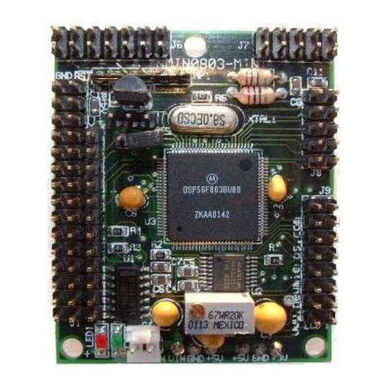
Page 12: Figure 10 - Board Features
Figure 10 – Board Features The features most important to you will be the connectors. The following list gives a brief description of each connector and the signals involved. Table 1 - Connectors PWM’s, Quad encoder, and interrupts CAN BUS Speed control CAN BUS Network Port unavailable V + &... -
Page 13: Circuit Description
PWM connector. The large chip at the center of the board is the CPU (DSP56F803). The two LED’s, Red and Green, are along the bottom of the CPU, and are dedicated to user control. -
Page 14: Reset
3.4 RESET A S80728HN Low Voltage Detector asserts reset when the voltage is below operating levels. This prevents brown out runaway, and a power-on-reset function. http://www.seiko-instruments.de/documents/ic_documents/power_e/s807_e.pdf 3.5 POWER SUPPLY A LM2937 reduces the VIN DC to a regulated 5V. In early versions a 7805C was used. The LM2937 was rated a bit less for current (500 mA Max), but had reverse voltage protection and a low drop out which was more favorable. -
Page 15: Trouble Shooting
4 TROUBLE SHOOTING There are no user serviceable parts on the NMIN-0803-Mini. If connections are made correctly, operation should follow, or there are serious problems on the board. As always, the first thing to check in case of trouble is checking power and ground are present. Measuring these with a voltmeter can save hours of head scratching from overlooking the obvious. -
Page 16: Online Resources
5.4 MaxFORTH™ Glossary Reference Page http://www.ee.ualberta.ca/~rchapman/MFwebsite/V50/Alphabetical/Brief/index.html This has explanations for the definitions for the procedural language "under" the IsoMax(TM) Finite State Machine language. 5.5 Motorola DSP56F803 Users Manual http://e-www.motorola.com/brdata/PDFDB/docs/DSP56F801-7UM.pdf 5.6 Motorola DSP56F800 Processor Reference Manual http://e-www.motorola.com/brdata/PDFDB/docs/DSP56800FM.pdf 6 CONNECTORS The NMIN-0803-Mini has 8 connectors. J1, J2, J3, J5, J6, J7, J8, are below: PWM, Quad Encoder &... -
Page 17: J1 Pwm, Quad Encoder & Interrupts
Figure 11 – Connector J1 6.1 J1 PWM, Quad Encoder & Interrupts PWMA0 PWMA1 PWMA2 PWMA3 PWMA4 PWMA5 IRQB ISA2 HOME0 IRQA ISA1 INDEX0 ISA0 PHASEB0 FAULT2 PHASEA0 FAULT1 +3.3V FAULT0 NMIN-0803-Mini User Manual... -
Page 18: J2 Can Bus Speed Control
Figure 12 – Connectors J2, J3, J4, J5 and J6 Connectors in above “top view, J1-to-left” picture and on page below, have same oriented (pin 1 upper left). 6.2 J2 CAN BUS speed control Jumper J2 can be used to switch between high-speed mode or silence mode CAN BUS operation based on TD2 output low or high respectively. -
Page 19: J7 Rs232
Figure 13 – Connectors J7, J8 and J9 Connectors in above “top view, J1-to-left” picture and on page below, have same oriented (pin 1 lower right). 6.7 J7 RS232 Connector TO 8 N.C. N.C. TO 7 TO 4 TO 6 N.C. -
Page 20: Manufacturer
7 MANUFACTURER New Micros, Inc. 1601 Chalk Hill Rd. Dallas, TX 75212 Tel: (214) 339-2204 Fax: (214) 339-1585 Web site: http://www.newmicros.com This manual: http://www.newmicros.com/store/product_manual/nmin-0803-mini.pdf Email technical questions: techsupport@newmicros.com Email sales questions: nmisales@newmicros.com 8 MECHANICAL Board size is 1.7” x 2.1” Mechanical Drawing on page 34 9 ELECTRICAL The total draw for the NMIN-0803-Mini under maximum speed is approximately 180... -
Page 21: Table 3 - Recommended Operating Conditions
Current drain per pin for PWM outputs — Junction temperature — °C Storage temperature range °C Table 3 - Recommended Operating Conditions Characteristic Symbol Unit Supply voltage Ambient operating temperature °C Table 4 - DC Electrical Characteristics ≤ Operating Conditions: = 0 V, V = 3.0–3.6 V, T = –40°... -
Page 22: Embedded Software Development
In this configuration, the PC user runs a program which communicates with IsoMax via the RS-232 cable. This allows interactive software development and testing. Details of IsoMax can be found on NMI’s website. 10.3 Compiler & Assembler Using this method, software is developed on the PC and transferred to the NMIN-0803- Mini using either the RS-232 (serial) cable or a JTAG cable. -
Page 23: With Jtag
10.3.1 With JTAG Figure 16 – Software Development using JTAG In this configuration, an editor is used to write a program on the PC, which is then compiled, assembled, and transferred to the 803-Mini via the JTAG cable using a Flash Utility on the PC. - Page 24 10.4 Blinking Green Led Test Program /*----------------------------------------------------- blinkgrn.c GPIO example program for the NMIN-0803-MINI (see http://www.newmicros.com) Modified from ledsmini.c by Peter F Gray (petegray@ieee.org) 6Feb03 --------------------------------------------------------*/ #include "scdefs.h" /* GPIO registers */ #define PEPUR 0x0FF0 #define PEDR 0x0FF1 #define PEDDR 0x0FF2 #define PEPER 0x0FF3 #define PEIAR 0x0FF4 #define PEIENR 0x0FF5...
- Page 25 unsigned int status; while (*b) { do status = *SCI0SR; while ((status&0xC000)!=0xC000); *a = *b; *b++; do status = *SCI0SR; while ((status&0xC000)!=0xC000); outscichar (a,b) int *a; unsigned char *b; int status; do status = *SCI0SR; while ((status&0xC000)!=0xC000); *a = *b; do status = *SCI0SR;...
- Page 26 *PEPER = 0x00F3; *PEDDR = 0x000C; *PEPUR = 0x00FF; val = 0x0008 | 0x0004; *PEDR = val; /* set both 'on' */ while (1) /* loop forever */ val |= 0x0008; /* PE3 high, */ *PEDR = val; /* Green Led On */ delay();...
-
Page 27: Pc Communication
11 PC Communication A variety of programs are available which allow a PC to communicate directly with the NMIN-0803-Mini. These programs are sometimes referred to as ‘Communications Programs’, ‘Comms programs’ or ‘Terminal Programs’ (because some emulate Computer Terminals). These programs run on the PC and are used in conjunction with an RS-232 cable, also known as a Serial Cable. -
Page 28: Maxterm
11.2 MaxTerm Provided DOS terminal program from New Micros, Inc. Usually provided in a ZIP. Un ZIP in a subdirectory, such as C:\MAXTERM. To start the program: click, or double click, the program icon. Maxterm.ico MaxTerm is a simple DOS-based communications package designed for program development on serial port based embedded controllers. -
Page 29: Hyperterminal
Status line mode indicators: r = rts, d = dtr, L = log file, S = sounds, K = redefinition, P = line pacing active 11.3 HyperTerminal Usually provided in Programs/Accessories/Communications/HyperTerminal. If not present, it can be loaded from the Windows installation disk. Use “Add/Remove Software”... -
Page 30: Reference
12 REFERENCE 12.1 Decimal / Octal / Hex / ASCII Chart OCT HEX Character Control Action Null character Start of heading, = console interrupt Start of text End of text End of transmission, not the same as ETB Enquiry, goes with ACK; old HP flow control Acknowledge, clears ENQ logon hand Bell, rings the bell... - Page 31 Asterisk (star, multiply) Plus Comma Hyphen, dash, minus Period Slant (forward slash, divide) Zero Three Four Five Seven Eight Nine Colon Semicolon < Less than sign Equals sign > Greater than sign Question mark At-sign Uppercase A Uppercase B Uppercase C Uppercase D Uppercase E Uppercase F...
-
Page 32: Simple Ascii Chart
Underscore Opening single quote Lowercase a Lowercase b Lowercase c Lowercase d Lowercase e Lowercase f Lowercase g Lowercase h Lowercase i Lowercase j Lowercase k Lowercase l Lowercase m Lowercase n Lowercase o Lowercase p Lowercase q Lowercase r Lowercase s Lowercase t Lowercase u... -
Page 33: Glossary
13 GLOSSARY .1” double and triple row connectors 24-pin socket 74AH04 9600 8N1 adapter ASCII CAN BUS Caps carrier board computing and control function communications channel communications settings COM1 COM2 COM3 COM4 controller controller interface board dedicated computer deeply embedded double male right angle connector double sided sticky tape embedded... -
Page 34: Articles And Suggested Reading
mobile robot Multitasking PCB board PWM connectors Power Supply Programming environment prototyping RS-232 R/C Servo motor real time applications. real time control registers RESET Resistor S80728HN serial cable “stamp-type” controller stand-alone computer board TJA1050 terminal program upgrade an existing application. Virtually Parallel Machine Architecture™...