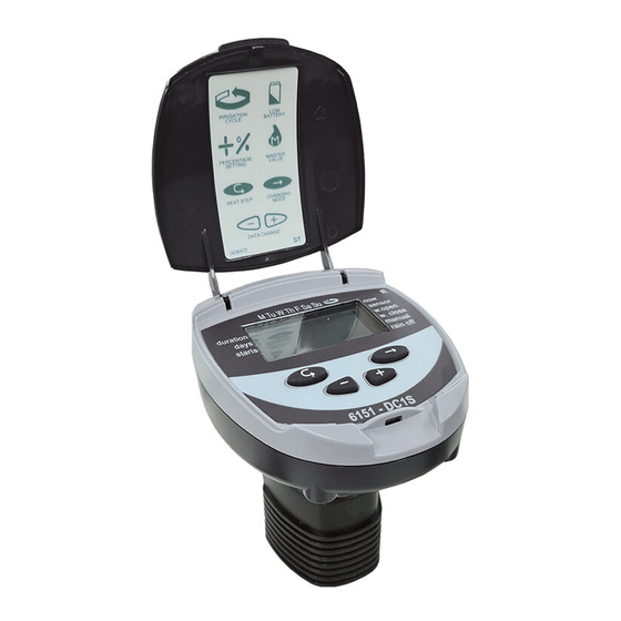
Galcon Dc-1 Installation And Operation Instructions Manual
Battery operated irrigation controller with valve
Hide thumbs
Also See for Dc-1:
- Operating instructions manual (28 pages) ,
- Installation and operating instructions manual (26 pages)
Summary of Contents for Galcon Dc-1
- Page 3 ��Gcוlcon 1. Parts ldentification 1. Cover 2. Push buttons 3. Controller display 4. Battery compartment cover 5. Adaptor 6. Mechanical operation lever 7. Solenoid 8. Hydraulic valve lmportant! Assembly of a filter upstream of the valve is mandatory. (See list of accessories page 20). Water Flow Direction 2.
- Page 4 ��Gcוlcon 2.2 Manual-Mechanical Operation The irrigation valve can be opened and closed independent of the controller's operation. Manual operation is useful when immediate irrigation is required, and the controller is not assembled yet. mechanical operation lever 2.3 Battery lnstallation Open the battery compartment cover. lnsert 9V batteries (see illustration).
- Page 6 2.5 Wiring the solenoids NOTE: Each zone requires a dedicated pair of wires from the controller. The four and six station controllers have red and black pairs of wires numbered for each valve. Notice there are 2 extra sets of wires. One set of wires (black and red) is stamped with the letter M representing the master valve, and one set of wires (yellow) with the letter S representing the rain sensor connection.
- Page 28 Kfar-Blum 1215000 Tel. 972-4-690-0222 Fax.972-4-690-2727 http//:www.galconc.com E-mail: info@galconc.com...


Need help?
Do you have a question about the Dc-1 and is the answer not in the manual?
Questions and answers