Table of Contents
Advertisement
Quick Links
Advertisement
Table of Contents

Subscribe to Our Youtube Channel
Related Manuals for Airspan ProST

Summary of Contents for Airspan ProST
- Page 1 UGD-D00111 Rev L ProST Hardware Installation User Guide Software Release 7.7...
-
Page 2: Acknowledgements
Information supplied by Airspan Networks Inc. is believed to be accurate and reliable. However, no responsibility is assumed by Airspan Networks Inc. for the use thereof nor for the rights of third parties which may be effected in any way by the use of thereof. -
Page 3: Table Of Contents
ProST Hardware Installation User Guide Table of Contents Acknowledgements .......................... 2 Copyright ............................2 Table of Contents ..........................3 Summary of Figures ......................... 6 Summary of Tables .......................... 8 Warnings and Cautions ........................9 ... - Page 4 ProST Hardware Installation User Guide R equired Tools ........................24 R adio Site Planning ....................... 25 3.4.1 Minimal Radio Path Obstructions .................. 25 3.4.2 Fresnel Zone Clearance ....................25 3.4.3 Radio Antenna Alignment .....................
- Page 5 ProST Hardware Installation User Guide C onnecting the SDA-4SDC Type II (Optional DC adapter) ..........54 A C Power Source ........................54 7.3.1 Using SDA-1 Type II ..................... 54 7.3.1.1 Changing the SDA-1 Type II Plug Prongs ............55 ...
-
Page 6: Summary Of Figures
ProST Hardware Installation User Guide Summary of Figures Figure 1 - ProST Maximum Output TX Power ................13 Figure 2 - ProST-2 Frequency Ranges ..................19 Figure 3 - Typical Setup ......................... 21 Figure 4 - ProST with integrated antenna ..................22 ... - Page 7 ProST Hardware Installation User Guide Figure 38 - SDA-MSG & PC to ProST .................... 51 Figure 39 - SDA-WiFi & PC to ProST ..................... 52 Figure 40 - ProST DC power connection ..................53 Figure 41 - ProST SDA-4SDC power connection ................54 ...
-
Page 8: Summary Of Tables
Table 2 - 1.4GHz Antenna Types ....................14 Table 3 - 2.5GHz Antenna Types ....................14 Table 4 - ProST Frequency Ranges ....................18 Table 5 - ProST Dimensions ......................28 Table 6 - SDA-1 Dimensions ......................30 ... -
Page 9: Warnings And Cautions
Warnings and Cautions Human Exposure to Radio Frequencies The ProST should be installed and operated from a minimum distance of 2 meters to your body. Radio Interference This equipment generates, uses, and can radiate radio frequency energy and, if not installed and used in accordance with the instructions, may cause harmful interference to radio communications. -
Page 10: Disclaimer Statement
ProST Hardware Installation User Guide Disclaimer Statement The information in this document is subject to change without notice and does not represent a commitment on the part of the vendor. No warranty or representation, either expressed or implied, is made with respect to the quality, accuracy or fitness for any particular purpose of this document. -
Page 11: Declaration Of Conformity
Este equipo cumple con los requisitos esenciales asi como con otras disposiciones de la Directive 1999/5/EC. Greek: ΜΕ ΤΗΝ ΠΑΡΟΥΣΑ Airspan ΔΗΛΩΝΕΙ ΟΤΙ Ο ΕΞΟΠΛΙΣΜΟΣ ΣΥΜΜΟΡΦΩΝΕΤΑΙ ΠΡΟΣ ΤΙΣ ΟΥΣΙΩΔΕΙΣ ΑΠΑΙΤΗΣΕΙΣ ΚΑΙ ΤΙΣ ΛΟΙΠΕΣ ΣΧΕΤΙΚΕΣ ΔΙΑΤΑΞΕΙΣ ΤΗΣ ΟΔΗΓΙΑΣ 1999/5/ΕΚ. Français: Cet appareil est conforme aux exigencies essentialles et aux autres dispositions pertinantes de la Directive 1999/5/EC. -
Page 12: Fcc Notice
ProST Hardware Installation User Guide FCC Notice Federal Communication Commission Notice This equipment has been tested and found to comply with the limits for a Class B digital device, pursuant to Part 15 of the FCC Rules. These limits are designed to provide reasonable protection against harmful interference in a residential installation. -
Page 13: Maximum Output Tx Power
ProST Hardware Installation User Guide Maximum Output TX Power Figure 1 ‐ ProST Maximum Output TX Power Caution: Do not set maximum output TX power to higher than local regulations. 700MHz Antennas Table 1 ‐ 700MHz Antenna Types Type Frequency range Gain Manufacturer Model number V-Pol MCX 698-746 MHz 7.5 dBi... -
Page 14: Ghz Antennas
ProST Hardware Installation User Guide 1.4 GHz Antennas Table 2 ‐ 1.4GHz Antenna Types Type Frequency range Gain Manufacturer Model number Omnidirectional 1425-1535 MHz 10 dBi TIL-TEK TA-1450 Omnidirectional 1425-1535 MHz 12 dBi TIL-TEK TA-1450-2 Panel 1425-1535 MHz 17 dBi TIL-TEK TA-1406 Direction Panel... -
Page 15: About This Guide
This guide provides step-by-step instructions for setting up and installing the ProST customer premise equipment (CPE) is part of Airspan's WiMAX family of WiMAX-based products. ProST also has a multimode model (ProST-2) based on the Rosedale chipset which supports both TDD and FDD. -
Page 16: Referenced Documentation
ProST Hardware Installation User Guide 1.4 Referenced Documentation For a detailed description of the Web-based configuration tool, refer to the WiMAX Web-based Management for Subscriber Stations User Guide. Page 16 Commercial in Confidence UWB-D00111 Rev L... -
Page 17: System Overview
ProST models support IP services at speeds of up to 37 Mbit/s over-the-air gross rates over channel bandwidths of up to 10 MHz in both uplink and downlink. ProST is available in numerous ETSI frequency bands, operating in FDD and TDD modes in numerous channels, see:... -
Page 18: Prost Frequency Ranges
ProST Hardware Installation User Guide ProST Frequency Ranges The table below lists the frequency range of ProST models currently available. This table will grow as more models become available. Table 4 ‐ ProST Frequency Ranges Frequency Band Channel Bandwidth 698 – 746 in MHz TDD mode 2.5 MHz... -
Page 19: Main Features
Note: Contact your Airspan representative for more information on the SDA- MSG VoIP extension module or the SDA-WiFi extension module. 2.2 ProST-2 Frequency Ranges The table below lists the frequency range of ProST-2, TDD/FDD Multimode models currently available. This table will grow as more models become available. Figure 2 ‐ ProST‐2 Frequency Ranges ... -
Page 20: Main Features
5 MHz 7 MHz 10 MHz Note: These ProST-2 Frequencies do not support the older type RSSI plug. 2.2.1 Main Features The ProST-2 provides the following main features: New CPE variants are equipped with Rosedale 2 chipset enabling FDD/TDD multimode operation, supporting 5 MHz and 7 MHz in both TDD and HFDD modes. -
Page 21: Architecture
Note: The SDA-1 Type II adapter can also be implemented with other Airspan's products (i.e. BSR, PPR, and SPR). For further information regarding these products, please contact your nearest Airspan dealer. The figure below displays a typical architecture setup of the ProST with an integrated antenna. Figure 3 ‐ Typical Setup 2.4 Models... -
Page 22: Prost Block Diagram
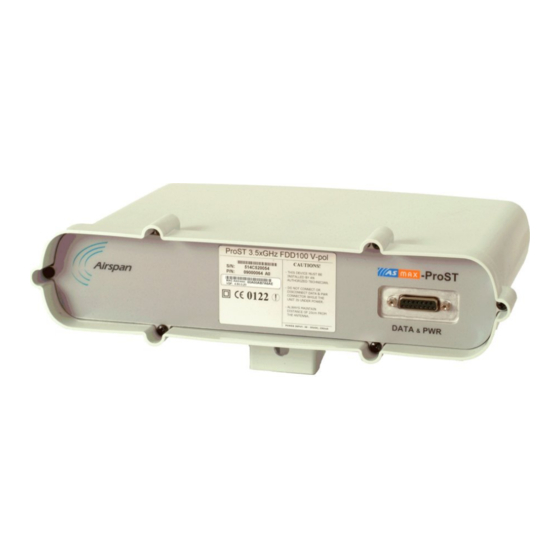
ProST with N-type connector for attaching third-party external antenna (i.e. no integrated antenna) The ProST model with the integrated antenna is shown below: Figure 4 ‐ ProST with integrated antenna The ProST model with the N-type connector for connecting an external antenna is shown below: Figure 5 ‐ ProST with external antenna 2.4.1 ProST Block Diagram Figure 6 ‐ Block Diagram ... -
Page 23: Prost Protocol Stack
Before any communication between ProST and BS can occur, the ProST must be positioned in a location that provides sufficient RF reception. To join a network, the ProST needs to perform a few tasks. First, the "Network Entry" process (defined in 802.16-2004) begins with the ProST scanning for a downlink (DL) signal from the base station, and then synchronizing to the DL channel. -
Page 24: Installation Prerequisites
R adio Site planning has been performed 3.1 Package Contents Examine the ProST shipping container. If you notice any damage, or missing items as listed in the Packing List, immediately notify the carrier that delivered the unit and contact a Airspan representative. -
Page 25: Radio Site Planning
ProST to the wall. The screw size depends on the structure of the building to which the ProST is to be attached. When selecting screw sizes, consideration must be given to the weight of the ProST and load that may be induced in windy conditions. -
Page 26: Figure 8 - Fresnel Zones
ProST Hardware Installation User Guide Figure 8 ‐ Fresnel Zones Fresnel Zones define the amount of clearance required from obstacles. These zones are composed of concentric ellipsoid areas surrounding the straight-line path between two antennas. Thus, the zone affects objects to the side of the path and those directly in the path. The first... -
Page 27: Radio Antenna Alignment
7.8 meters) above ground level (or clutter level). 3.4.3 Radio Antenna Alignment Once the ProST is installed and aimed in the general direction of the base station, it is recommended to measure the received signal strength (RSS) to determine the signal strength received from the base station, and to precisely align the ProST for maximum signal strength. -
Page 28: Physical Description
(indoor DC unit) (optional) 4.1 ProST Physical Description The ProST is an encased outdoor radio providing access to communication ports on its bottom panel. The ProST's back panel provides holes for ProST mounting. This subsection provides the following ProST physical descriptions:... -
Page 29: S Da-1 Physical Description
Figure 11 ‐ ProST ports Note: ProST models that use third-party external antennas provide an N-type receptacle for attaching an external antenna. 4.2 SDA-1 Physical Description The SDA-1 is an integrated Ethernet and AC/DC power supply adapter that simply plugs into a standard electrical wall outlet (110/240 VAC). -
Page 30: Physical Dimensions
The SDA-1 provides a green power LED (labeled POWER), located on its front panel. This LED light not only indicates the presence of power, but also can indicate incorrect SDA-1 port assignment for the network cables, i.e. from the ProST and computer. For a detailed description of the POWER LED, see roubleshooting. -
Page 31: Physical Dimensions
ProST Hardware Installation User Guide Figure 13 ‐ SDA‐4S Type II This subsection provides the following SDA-4S physical descriptions: D imensions P orts L EDs 4.3.1 Physical Dimensions The SDA-4S Type II and SDA-4S/VL Type II physical dimensions are described in the table below: Table 8 ‐ SDA‐4S Type II dimensions ... -
Page 32: Leds
ProST Hardware Installation User Guide Note: The ports of the SDA-4S models support Auto Negotiation, allowing automatic configuration for the highest possible speed link (10BaseT or 100BaseT), and Full Duplex or Half Duplex mode. In other words, the speed of the connected device (e.g. -
Page 33: Ports
(100BaseT) or SDA-4S adapter and ProST Orange Blinking Traffic currently flowing between SDA-4S and (10BaseT) ProST No link between SDA-4S and ProST Physical link (10BaseT or 100BaseT) between 1, 2, 3, 4 Yellow (100BaseT) or SDA-4S and subscriber's Ethernet network Orange... -
Page 34: Mounting The Prost
The ProST offers two optional methods for outdoor mounting: W all mounting P ole mounting For either mounting methods, the ProST provides mounting holes molded into its back panel for attaching the wall or pole-mounting brackets, as displayed in the figure below. Figure 16 ‐ ProST‐ rear view ... -
Page 35: Wall Mounting
ProST Hardware Installation User Guide Figure 17 ‐ Mount separation The figure below illustrates the minimum separation between mounted ProST's when transmitting on the same sector: Figure 18 ‐ Mount separation 1 5.1 Wall Mounting The ProST is wall mounted in two main stages: Attaching the mounting bracket to the ProST's mounting holes... -
Page 36: Figure 19 - Wall Mount Template
The screw size depends on the structure of the building to which the bracket is to be attached. When selecting screw sizes, consideration must be given to the weight of the ProST and load that may be induced in windy conditions. -
Page 37: Figure 20 - Mounting Bracket
ProST's mounting holes. Loosely fasten with the M10-hex nuts. Figure 21 ‐ Mounting to bracket 6. Adjust the horizontal positioning of the ProST, and then tighten the two M10 x 1.5-hex head screws (20mm length) with the M10 hex nuts. Max torgue for M10 is 44Nm (32lbf.ft.). -
Page 38: Pole-Mounting
ProST's back panel and the supplied (when ordered) pole-mounting brackets. The pole- mounting bracket is designed to support the ProST on a round pole of 45 mm in diameter. The figure below illustrates a summary of the ProST pole-mounting procedure. -
Page 39: Figure 24 - Mounting Bracket Attached
M10-hex head screw through the mounting bracket and ProST's mounting holes. Fasten the M10-hex head screw (one is provided with a built-in nut while the other requires you to insert an M10-hex nut into the ProST's mounting hole). Max torgue for M10 is 44Nm (32lbf.ft.). -
Page 40: Figure 25 - Pole Mount Clamping Bracket
Adjust the vertical position of the ProST by choosing a final elevation hole as described in Step 2. Lock the ProST at the desired position by inserting the locking bolt in the desired position and fastening it tightly. Fasten tightly the bolt in the pivot hole. The figure below illustrates the angles (in degrees) of each elevation hole. -
Page 41: Figure 27 - Elevation Holes
Figure 27 ‐ Elevation holes Note: A thread-locking compound must be used to prevent the bolts from working loose. ProST positioning is obtained in two planes by adjustment of the mounting bracket assembly as shown below: Figure 28 – ProST positioning It is important to provide strain relief and drip loop for Cat-5e cables. Create a drip loop and strain relief using cable tie, to tie cable to pole, as displayed in the figure below: Figure 29 ‐ strain relief ... -
Page 42: Mounting The Sda-4S
ProST Hardware Installation User Guide 5.3 Mounting the SDA-4S The SDA-4S Type II adapters (all types) can be mounted either horizontally on a desktop or vertically on a wall. 5.3.1 Desktop Mounting Desktop mounting is made possible by the existence of four feet, each located on the four corners of the SDA-4S bottom panel. -
Page 43: Figure 31 - Sda-4S Mounting Template
Note: The SDA-4S is supplied with a 1-metre AC power lead assembly. Therefore, ensure the unit is mounted within reachable distance to the customer's mains power outlet. Note: The maximum cable run between SDA-4S and ProST is 100 meters. Therefore, ensure the unit is mounted within reachable distance. Page 43... -
Page 44: Network Cabling
Note: Use CAT-5e unshielded cable only. 6.1.1 Connecting the SDA-1 Type II The ProST connects to the SDA-1 using a CAT 5Ee cable with 8-pin RJ-45 connectors on either end. The ProST provides a 15-pin D-type port for interfacing with the SDA-1. However, for allowing the use of RJ-45 connectors, your ProST kit includes a DB15-to-RJ45 adapter that can easily be attached to the ProST's 15-pin D-type port. -
Page 45: Figure 33 - Prost & Sda-1
To connect the ProST to the SDA-1: 1. Attach the DB15 side of the DB15-to-RJ45 adapter to the ProST's 15-pin D-type port (female), labeled DATA & PWR. 2. Plug the RJ-45 connector of the Category 5 Ethernet cable (not supplied) into the RJ-45 port of the DB15-to-RJ45 adapter. -
Page 46: Connecting The Sda-4S Type Ii, Sda-4S/Vl Type Ii Or Sda-4S/Dc Type Ii
However, for allowing the use of RJ-45 connectors, your ProST kit includes two DB15-to- RJ45 adapters that can easily be attached to the 15-pin D-type ports of the ProST and SDA-4S. The cable setup for ProST to SDA-4S connectivity is as follows:... -
Page 47: Connecting To Lan Network
Figure 35 ‐ ProST & SDA‐4S 6.2 Connecting to LAN Network The ProST typically interfaces with the subscriber's LAN network using the indoor SDA-1 Type II adapter. This adapter provides one 100BaseT interface. However, optional IDU adapters (SDA- 4S Type II, SDA-4S/VL Type II or SDA-4S/DC Type II) are offered that provide four LAN ports for interfacing with the subscriber's LAN network. -
Page 48: Connecting The Sda-1 Type Ii
Function 8-Pin RJ-45 To connect the ProST to the subscriber's network/PC (via SDA-1 Type II): 1. Plug the supplied Category 5e Ethernet cable into the SDA-1's RJ-45 port labeled LAN/PC. 2. Plug the loose end of the Category 5e Ethernet cable into the computer's LAN port. -
Page 49: Connecting The Sda-4S Type Ii, Sda-4S/Vl Type Ii Or Sda-4S/Dc Type Ii
ProST Hardware Installation User Guide 6.2.2 Connecting the SDA-4S Type II, SDA-4S/VL Type II or SDA-4S/DC Type II The SDA-4S Type II, SDA-4S/VL Type II or SDA-4S/DC adapters (referred hereafter as SDA-4S) provide four RJ-45 (100BaseT) ports for interfacing with the subscriber's LAN network. The difference between these adapters is that the SDA-4S/VL supports VLAN functionality at the ports. -
Page 50: Connecting The Sda-Msg
Note: For pinout refer to SDA-1 Type II above. To connect the SDA-MSG’s Radio port to Ethernet network and the RJ 45 port to ProST: 1. Plug the CAT 5e Ethernet cable into the MSG unit 8-pin RJ-45 LAN port. -
Page 51: Connecting The Sda-Wifi
Note: For pinout refer to SDA-1 Type II above. To connect the SDA-WiFi’s LAN port(s) to Ethernet network and the RJ 45 port to ProST: 1. Plug a CAT 5e Ethernet cable into one or more of the SDA-WiFi unit's 8-pin RJ-45 LAN ports. -
Page 52: Figure 39 - Sda-Wifi & Pc To Prost
ProST Hardware Installation User Guide Figure 39 ‐ SDA‐WiFi & PC to ProST Page 52 Commercial in Confidence UWB-D00111 Rev L... -
Page 53: Connecting To Power
Surge Immunity standard EN 61000-4-5. 7.1 DC Power Source ProST can be connected directly to a DC power supply unit that supplies 10 – 52 VDC (0.2 to 0.9 A; 15W maximum, assuming up to 100-m cable length between ProST and power source). -
Page 54: Connecting The Sda-4Sdc Type Ii (Optional Dc Adapter)
Figure 41 ‐ ProST SDA‐4SDC power connection 7.3 AC Power Source ProST is powered from an AC power source when implementing the SDA-1 Type II, which is plugged directly into a standard electrical wall outlet (110/240 VAC). The optional IDU adapters (SDA-4S Type II and SDA-4S/VL Type II) also power ProST from the subscriber's AC electrical wall outlet. -
Page 55: Changing The Sda-1 Type Ii Plug Prongs
ProST Hardware Installation User Guide The AC power cabling consists of the following stages: C hanging SDA-1 Type II plug prongs P lugging SDA-1 into wall outlet 7.3.1.1 Changing the SDA-1 Type II Plug Prongs The SDA-1 Type II allows you to attach plug prongs suited to the electrical wall socket of the country in which you are installing the equipment. -
Page 56: Using Sda-4S Type Ii And Sda-4S/Vl Type Ii
ProST Hardware Installation User Guide Figure 43 ‐ ProST to power Verify that your SDA-1 Type II is on and receiving power by checking that the LED labeled POWER is lit (see S DA-1 Type II LED description). If it is not lit, see roubleshooting. -
Page 57: Figure 45 - Connecting To Ac Power
ProST Hardware Installation User Guide 3. Verify that the power is received by the SDA-4S by checking that the POWER LED light is Figure 45 ‐ Connecting to AC power Verify that your SDA-4S is on and receiving power by checking that the LED labeled POWER is lit... -
Page 58: Power Cable Connection
ProST Hardware Installation User Guide 8 Power Cable Connection In the SDA-4SDC installation Kit there are two polarized and genderless unassembled Anderson Powerpole power connectors: for positive connection and black for the negative connection. Figure 46 ‐ Power connectors (Anderson Powerpole) The power connectors consist of housing (hood and a contact pins). The contact pin is displayed below: Figure 47 ‐ Contact pin ... -
Page 59: Figure 50 - Connect To Power Source
ProST Hardware Installation User Guide left and the black on the right. The housing dovetails should be mated fully. 2. Connect the power connectors to the SDA-4SDC power receptacles so that the connectors' color matches the receptacle's color, red to red (positive), and black to black (negative). -
Page 60: Connecting Lightning And Surge Protector
To install the lightning protector: 1. Connect the protector in the direction according to the labels. The end labeled SURGE accepts the cable from the ProST; the end labeled PROTECTED accepts the cable from the IDU. 2. Feed the CAT 5e cable through the grommet (for each side). If the RJ-45 connector is already crimped to the other end, ensure that you have fed the cable through the gland nut beforehand. -
Page 61: Polyphaser Wiring Diagram
ProST Hardware Installation User Guide 9.1 PolyPhaser Wiring Diagram Figure 51 ‐ Working with SDA Figure 52 ‐ RJ45 working with SDA 1. Mount and ground the protector outdoors with the provided 2 x 8-32 screws according to the template illustrated below (showing distances between centers of the two mounting holes). -
Page 62: Figure 54 - Sda-1 + Polyphaser + Prost
ProST Hardware Installation User Guide Figure 54 ‐ SDA‐1 + PolyPhaser + ProST Page 62 Commercial in Confidence UWB-D00111 Rev L... -
Page 63: Figure 55 - Sda-4S + Polyphaser + Prost
ProST Hardware Installation User Guide Figure 55 ‐ SDA‐4S + PolyPhaser + ProST Figure 56 ‐ SDA‐4SDC + PolyPhaser + ProST Page 63 Commercial in Confidence UWB-D00111 Rev L... -
Page 64: Rssi Led Plug Adapter For Antenna Alignment
10 RSSI LED Plug Adapter for Antenna Alignment The RSSI LED Plug is a small adapter that allows you to accurately position (align) the ProST for optimal radio frequency signal reception with the Base Station. The RSSI LED Plug adapter provides LEDs that indicate the ProST's received signal strength (RSS) with the Base Station. -
Page 65: Led Status
67 - 70 66 dB+ Before connecting the power adapter to the ProST, you need to connect the AC power cable (that connects to the subscriber’s power outlet) to the adapter, as described in the following procedure. To connect the RSSI LED Plug Adapter: 1. -
Page 66: Figure 57 - Rssi Connections
ProST Hardware Installation User Guide The following diagram illustrates the RSSI LED plug connections: Figure 57 ‐ RSSI connections Note: RSSI response time has been proportionally increased (from previous models) to enable longer alignment. Page 66 Commercial in Confidence UWB-D00111 Rev L... -
Page 67: Connecting External Antenna
11 Connecting External Antenna The ProST model without a built-in antenna provides an N-type port for connecting a third-party external antenna. The addition of an external antenna allows greater RF sector coverage than the standard ProST built-in antenna model. The external antenna is typically implemented in scenarios where the ProST is deployed at relatively far distances from the base station. - Page 68 ProST Hardware Installation User Guide Page 68 Commercial in Confidence UWB-D00111 Rev L...
-
Page 69: Appendix
ProST Hardware Installation User Guide 12 Appendix 12.1 Troubleshooting The table below provides some possible solutions to problems that may arise if the ProST is incorrectly installed: Table 18 ‐ Troubleshooting Problem Possible Cause Solution SDA-1 (and therefore, No electricity at wall outlet... - Page 70 ProST Hardware Installation User Guide Gigahertz. One GHz represents 1 billion cycles per second Half-Duplex FDD HFDD Hertz Integrated Access Device Indoor Unit (i.e. SDA-1 Type II, SDA-4S Type II, or SDA-4S/VL Type II) Internet Protocol Internet Service Provider Local-Area Network Media Access Controller.
-
Page 71: Revision History
Airspan Networks have introduced the A irspan Tracker application to enable prompt and efficient Customer Support services. If you do not have an Airspan Tracker account, please obtain login credentials by filling-in the form in the main page " Register New Account".
Need help?
Do you have a question about the ProST and is the answer not in the manual?
Questions and answers