Table of Contents
Advertisement
Advertisement
Table of Contents

Subscribe to Our Youtube Channel
Related Manuals for Simply Automated UCS-01


Summary of Contents for Simply Automated UCS-01
- Page 1 Controller, Scheduler-Timer Model UCS-01 version 1.48+ User Guide...
- Page 2 Controller, Scheduler-Timer Model UCS-01 QUICK REFERENCE GUIDE IDLE SCREEN Schedule Mode (change via 'Set Time') [OFF] = No Events Operate 03:50PM [RUN] Time [RUN] = Run 'R' Events Operate 05/09/06 Tue Date [VAC] = Vacation 'V' and Run 'R' Events Operate [ALT] = Vacation ‘V’...
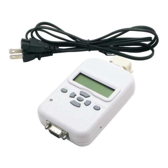
- Page 3 Controller, Scheduler-Timer Model UCS-01 DESCRIPTION The UPB Controller, Scheduler-Timer (model UCS) provides control of UPB devices or UPB scene links according to a user defined event or schedule. It is designed to communicate with a UPB network when connected to a standard power receptacle; using the L-shaped power connector or the 6 foot power cord, both included.
-
Page 4: Important Safety Instructions
Controller, Scheduler-Timer Model UCS-01 IMPORTANT SAFETY INSTRUCTIONS When using electrical products, basic safety precautions should always be followed, including the following: 1. READ AND FOLLOW ALL SAFETY INSTRUCTIONS. 2. Keep away from water. If product comes into contact with water or other liquid, unplug immediately. - Page 5 Controller, Scheduler-Timer Model UCS-01 FUNCTION / NAVIGATION The Scheduler-Timer has an LCD display with 2 lines of 16 characters, a diagnostic LED, 7 buttons, a polarized power connector and a DB-9 serial port. The 7 buttons provide easy navigation through the menus on the LCD display and are described as follows: MENU: Provides access to the main menu from the Idle Screen.
-
Page 6: Initial Configuration
Controller, Scheduler-Timer Model UCS-01 INITIAL CONFIGURATION NOTE: In order to completely configure the Scheduler-Timer it is necessary to know the Network ID, Device ID(s) and Scene-Link ID(s) to be controlled. Writing down the Device ID or Scene-Link ID for each UPB device to be scheduled is recommended. The ID information is found in the UPStart network file. - Page 7 Controller, Scheduler-Timer Model UCS-01 Step B: Set Location Press MENU from the Idle Screen. Press the Down button to select Set Location. 2)Set Time 3)Set Location Press ENTER button to view the Set Location sub-menu 1)ZIP Code OR 2)Long&Latitude Select Zip Code and press ENTER o Zip Code –...
- Page 8 Controller, Scheduler-Timer Model UCS-01 Select Set Events and press ENTER utton. Hint: Each Event in the Scheduler-Timer requires the Device ID of the UPB device or 03:50:47PM [RUN] the Scene-Link ID of the UPB scene-link to be 05/09/06 Tue controlled. Before setting up events, it is...
-
Page 9: Delete Events
Controller, Scheduler-Timer Model UCS-01 01)---SMTWTFS R 01)003 SMTWTFS R 02)023 SMTWTFS V 12:00A 12:00A D0 DUSK+15 11:00P D0 06:00P 11:00P LA Event 01), Device 003, all days Event 02), Link 023, all days Event 01), factory default of the week, a... -
Page 10: Link Mode
Controller, Scheduler-Timer Model UCS-01 Set Randomness Vacation random +/- minutes=015 Vacation Events are designed so that the ON and OFF time can be random, from plus or minus 1 to 60 minutes, giving the home a 'lived in' look. As an example, if Vacation random limit is set to +/-10... -
Page 11: Add Device
Controller, Scheduler-Timer Model UCS-01 CIM Mode To configure the Scheduler-Timer to operate as a Computer Interface 7)Set Contrast Module (CIM), allowing a PC with UPStart to access a UPB network, 8)CIM Mode select the CIM mode from the menu and press ENTER button to initiate CIM mode operation. - Page 12 Controller, Scheduler-Timer Model UCS-01 Add Link The Add Link function will add a scene-link # to the receive component table of one or more devices at the same time. A scene-link # will need to be selected when adding the link to devices. If the scene-link is an existing link from a button or rocker you can determine (read) the link # by using the Read Link function in the Tools menu (see Read Link section, page 13).
- Page 13 Controller, Scheduler-Timer Model UCS-01 To delete a scene-link # from one or more devices: Go to the UCS and press the Menu button to view the main menu. Press the down button 7 times to select Tools, then press Enter .
- Page 14 UPB devices spread throughout the home. For assistance with noise or attenuation issues, please call Simply Automated Technical Support at 800-630-9234x138, or write Support@Simply- Automated.com.
- Page 15 Controller, Scheduler-Timer Model UCS-01 Clock Source Sync to 60Hz = Y The Scheduler-Timer is synchronized by the 60hz power signal for maximum accuracy. Selecting N for NO synchronization sets the Scheduler-Timer to operate using the internal clock, which has a maximum error of + 1.7 seconds per day.
- Page 16 Controller, Scheduler-Timer Model UCS-01 SCHEDULE NOTES Hint: complete the notes before programming the events. Event Device / Link ID; Description Event # Time Time Mode LA/D# (days of the week - SMTWTFS) Example Link 001; welcome home (all) 10:00PM Dusk 11:30PM Link 002;...
Need help?
Do you have a question about the UCS-01 and is the answer not in the manual?
Questions and answers