
Subscribe to Our Youtube Channel
Related Manuals for Command Technologies COMMANDER HF-2500

Summary of Contents for Command Technologies COMMANDER HF-2500
- Page 1 COMMANDER HF-2500/ HF-2500 MAGNUM LINEAR AMPLIFIER MADE IN THE U.S.A. BY HAMS FOR HAMS COMMAND TECHNOLOGIES, Inc. 15719 CR 2.50 P. O. BOX 326 EDON, OHIO 43518-0326 419 459-4689 800-736-0443...
- Page 2 We appreciate your purchase of a Command Technologies product and assure you of continued factory support of your investment at all times.
-
Page 3: Specifications
SPECIFICATIONS COMMANDER HF-2500/ HF-2500 MAGNUM LINEAR AMPLIFIER Band Coverage: 160, 80, 40, 20, 17, and 15 meter amateur radio bands, 12 and 10 meter Export model; also useable in U.S.A. upon proof of proper license. Types of Emissions: SSB, FM, CW, AM, RTTY, SSTV... -
Page 4: Unpacking Instructions
Introduction The Commander HF-2500/HF-2500 MAGNUM are class AB2 linear power amplifiers. They have been designed for operation on all amateur frequencies from 1.80 Mhz to 21.450 Mhz excluding the 30 meter band. Two Eimac 3CPX800A7 ceramic-metal triodes, configured in a grounded grid circuit, allows for conservative operation at 1500 watts continuous carrier output. -
Page 5: Cautions And Warnings
If any problem occurs which can not easily be corrected, contact the manufacturer for assistance. Accessory warnings Your new Commander HF-2500/HF-2500 MAGNUM has the capability of 1500 watts output continuous carrier without time limit. Many accessories such as power meters, traps. and baluns have power ratings for the old 1,000 watt input (600 watt output) power restriction. -
Page 6: Transformer Installation
COMMAND TECHNOLOGIES INC. 15719 CR 2.50 P.O. BOX 326 EDON, OHIO 43518 TEL: 419-459-4689 TRANSFORMER INSTALLATION When mounting the hypersil transformer, place the HF-2500\HF-2500 MAGNUM so the front panel faces your body. Align the transformer so the Danger High Voltage label reads right. The wire leads coming out of the transformer should be to the rear and the connector to the right. - Page 7 Connection Diagram High Speed Switching Connect the RF output of your transceiver to the RF IN connector on the rear of the HF-2500\HF-2500 MAGNUM with 50 ohm coax. Connect the existing station antenna system to the RF OUT connector on the HF-2500\HF-2500 MAGNUM with RG-8 type coax.
-
Page 8: Tuning Procedure
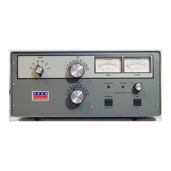
TUNING PROCEDURE 1. Set the front panel controls to the following positions: ON - OFF Switch....OFF STANDBY - OPERATE..STANDBY METER SWITCH....Vp BAND SWITCH......DESIRED BAND TUNE CONTROL....LOG SCALE ON DATA SHEET LOAD CONTROL....LOG SCALE ON DATA SHEET 2. After you have preset the above controls and the amplifier is properly connected to a suitable load, switch the ON - OFF to the on position. - Page 9 TUNING PROCEDURE CONTINUED 5. If your planned operation is on SSB, you should adjust the load control slightly counter-clockwise, reducing the output slightly about 30 to 50 watts. This adjustment is necessary to insure that the amplifier is sufficiently loaded to handle the plate current peaks caused by the complex voice patterns during SSB operation.
-
Page 10: Theory Of Operation
Theory Of Operation The Commander HF-2500\HF-2500 MAGNUM uses a pair of C.P.I. Eimac 3CPX800A7 ceramic/metal triodes in a class AB2 grounded grid configuration. Nominal drive power of 50 to 60 watts will deliver 1500 watts of clean RF output power. This amplifier will operate on the following amateur bands: 160,80,40,20,17, and 15 meters. -
Page 11: Tuned Input Adjustments
TUNED INPUT CIRCUITS The tuned input circuits utilize an L-C-L or "T" impedance matching circuit with a high "Q" design. These circuits employ RF phase compensating capacitors to reduce intermodulation products. The use of mica trimmer type capacitors allows adjustments to precisely match the transceiver to the amplifier. - Page 12 AUTOMATIC DRIVE LIMITING CONTROL An adjustable automatic level control (ALC) circuit limits the peak output power. When properly set, this circuit insures that the amplifier can not be overdriven. Rear panel access allows for easy manual adjustment . A sample of the RF input derives the ALC voltage. Additionally this amplifier has an RF negative feedback resistance in the cathode circuit to help cancel excessive RF drive without reducing the amplifier's gain.
-
Page 13: High Voltage Supply
OUTPUT FILTER CIRCUIT The PI variable network filter transforms the plate load impedance from approximately 2,500 ohms down to 200 ohms, Two air variable capacitors, and an associated inductor, accomplish this transformation. A heavy duty band switch selects the proper inductance from two high "Q"... -
Page 14: Limited Warranty
Correct maintenance, repair, and use are important to obtain proper performance from this product. Therefore, carefully read the Instruction Manual. This warranty does not apply to any defect that Command Technologies, Inc. determines is due to 1. Improper maintenance or repair including the installation of parts or accessories that do not conform to the quality and specifications of the original parts.
Need help?
Do you have a question about the COMMANDER HF-2500 and is the answer not in the manual?
Questions and answers