
Related Manuals for MicroNet CE-507

Summary of Contents for MicroNet CE-507
- Page 1 Revision C January 2011...
-
Page 2: Important Notice
Micronet Ltd. Information in this manual is subjected to change without notice. Micronet shall have neither liability nor responsibility to any person or entity with respect to any loss or damages arising from the information contained in this book. Other company and brand products and service names are trademarks or registered trademarks of their respective holders, for example: ARM Cortex™, Microsoft™, and Microsoft™... -
Page 3: Table Of Contents
Usage Precautions ........................8 Power Supply ........................... 9 Introduction ......................10 CE-500 Platform Overview ......................10 CE-504 and CE-507 Models ......................10 Displays ..........................11 Physical Interfaces ........................11 Optional Wireless Modules ......................11 Fixed Mount and Portable Configuration ..................11 Development Tool Kit ......................... - Page 4 Table of Contents Device Connector Slot - Rubber and Plastic Covers ..............25 Real Time Clock (RTC)......................25 Watchdog ..........................25 User Interface ........................... 26 Display ........................... 26 Touch Screen and Stylus ......................26 Light Sensor ........................... 27 Keypad........................... 27 Customized Front Panel Label (Option) ..................
- Page 5 Table of Contents GPS ............................54 Wireless LAN and Bluetooth Class2 .................... 55 Peripheral Interfaces ........................57 CANBus (J1939) ........................57 External Audio Module ......................57 External Video Module ......................58 Additional Integrated Options ...................... 58 Accelerometer ......................... 58 Platform Accessories ....................59 Accessory Cables ........................
- Page 6 Table of Contents Physical Characteristics ......................94 Appendices ......................95 Appendix A ..........................95 Regulations & Certifications ...................... 95 GDUTUG500/01 CE-500 MDT Hardware Guide 6 / 97...
-
Page 7: Preface
Preface Revision History Revision Date Change February, 2010 Document created March, 2010 Adding new power management functionality April, 2010 Keypad keys names has been changed (Backspace to Left) January, 2011 Adding CE and FCC certifications. GDUTUG500/01 CE-500 MDT Hardware Guide 7 / 97... -
Page 8: Safety Precautions
Preface Safety Precautions Read the following safety precautions before installation or operation. WARNING! Abnormal Conditions Should the CE-500 become hot or start to emit smoke or a strange odor, immediately turn off the power and contact your original dealer or an authorized service provider. Continued usage is dangerous and may result in fire or electric shock. -
Page 9: Power Supply
Preface Safety Precautions CAUTION LCD Screen Never apply heavy pressure on the CE-500 device display or subject it to strong impact. Doing so may crack the screen or LCD panel glass, which may result in personal injury or major damage to the device. Should the LCD panel glass break, do not touch the liquid inside. -
Page 10: Introduction
The CE-500 is built to withstand a wide temperature range, vibrations, shock, and endure the rough working conditions in commercial vehicle environment. Micronet implemented the CE-500 platform in two product models, which are ergonomically designed for use in commercial vehicles of different sizes. Each model provides a user interface optimized for use in certain conditions. -
Page 11: Ce-504 And Ce-507 Models
Basic configuration. To highlight those extensions, each extension includes an "option" remark on the feature description. To support operation in various conditions, you can use different displays with CE-504 and CE-507. The single core-processing unit supports the following display sizes: ... -
Page 12: Development Tool Kit
Device cradle for recharging, mounting and connectivity Micronet's CE-500 Developers Package provides all tools required for application development quick- start, product testing, and product evaluation. The Developers Package includes 20 hours of technical support and contains all essential hardware and software components as described in the following sections. -
Page 13: Ce-500 Platform Key Feature Specifications
Introduction CE-500 Platform Key Feature Specifications CE-504 CE-507 WQVGA (480 X 272) WVGA (800 X 480) Table 1 – BASIC configuration Basic configuration features Details Platform Core - Microsoft Windows Embedded CE 6 Core License Operating system - Professional license available (optional) - Page 14 Drop According MIL standard - RAM® Mounts compatible mounting arm Device Mounting - Micronet mounting arm available (optional) - Device cradle available (optional) Environmental - Operating: -4 °F to +158 °F (-20 °C to +70 °C) - Storage: -22 °F to +176 °F (-30 °C to +80 °C) Temperature range - Operating with internal battery option: 14 °F to 140 °F (-10 °C to...
-
Page 15: Ce-500 Platform Optional Modules
- Supporting all the platform device models - Cables connection infrastructure with mechanical cover option Device cradle - Device mounting with quick release mechanism - RAM® Mounts compatible mounting arm - Micronet mounting arm available (optional) GDUTUG500/01 CE-500 MDT Hardware Guide 15 / 97... -
Page 16: Ce-500 Platform Accessories
Introduction CE-500 Platform Accessories Features Details Power Supply Wall power adaptor for device 110V / 220V AC to 5V DC Wall power adaptor for cradle 110V / 220V AC to 12V DC Peripheral Cables Main interface cable Device “Con1” to power, USB, serial, and I/O connectors Enhanced interface cable Device “Con2”... -
Page 17: Ce-50X Device Components
Introduction CE-50X Device Components Customized Front Panel Label Display Light Sensor Keypad Internal Speakers Internal Microphone Keypad Figure 1 – CE-504 Model, Front Panel components For more information on CE-504 front panel components, see: Display, on page Customized Front Panel Label, on page ... -
Page 18: Ce-507 Front Panel Components
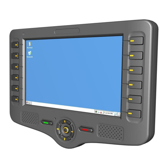
Customized Front Panel Label Light Sensor Internal Microphone Internal Speakers Internal Speakers Keypad Figure 2 – CE-507 Model, Front Panel components For more information on CE-507 front panel components, see: Display, on page Customized Front Panel Label, on page ... -
Page 19: Ce-50X Model, Bottom Panel Components
Introduction CE-50X Device Components Cable mounting Enhanced Terminal Main Terminal “Con2” Connector screw inserts “Con1” Connector Optional External Audio Optional External Video and “Con4” Connector CANBus “Con3” Connector Figure 3 – CE-50X Model, Bottom Panel components For more information on CE-50X bottom panel components, see: ... -
Page 20: Ce-50X Model, Right Side Panel
Introduction CE-50X Device Components Memory Card Support Device Connector Slot - Rubber and Plastic Covers Device connectors slot 5V Power-in connector USB OTG Port Figure 4 – CE-50X Model, Right Side Panel (Device Connector Slot) and Slot cover components For more information on CE-50X Right side panel components, see: ... -
Page 21: Ce-50X Model, Left Side Panel Component
Introduction CE-50X Device Components Error! Reference source not found., on page Error! Bookmark not defined. Stylus Device Connector Slot - Rubber and Plastic Covers SIM card slot Figure 5 – CE-50X Model, Left Side Panel and SIM Card Slot cover components For more information on CE-50X Left side panel components, see: ... - Page 22 Introduction CE-50X Device Components Mounting Arm screw inserts Stylus Device assembly screws Figure 6 – CE-50X Model, Rear Panel components For more information on CE-50X Rear panel components, see: Mounting Arm screw inserts, on page Stylus, on page GDUTUG500/01 CE-500 MDT Hardware Guide 22 / 97...
-
Page 23: Technical And Functional Details
For more details on device’s operating system architecture, refer to the CE-500 Software Developer's Guide. The CE-500 platform supports Microsoft Visual Studio 2005 or 2008 and C++ (Win32 API) or Microsoft .NET Compact Framework 3.5. Micronet Development Toolkit (DTK) includes the following components: Full Micronet SDK ... -
Page 24: Processor
Technical and Functional Details Platform Core For more details on development infrastructure, product tolls, and DTK contents, refer to the CE-500 Getting Started Guide. TI OMAP3503 High-performance Superscalar ARM Cortex™-A8 The device provides a total of 256 MB of RAM memory (DDR type), which is partially allocated for system and application usage. -
Page 25: Device Connector Slot - Rubber And Plastic Covers
Technical and Functional Details User Interface Speed: x133 Clocks: Identification mode – 400 kHz, data mode 20 MHz The MMC / SD (SDHC) card slot is located on the right side panel. By default, a user can physically access the slot. -
Page 26: User Interface
The CE-504 device model provides a 4.3” Touch Color display with WQVGA (480 X 272 pixels) resolution. The CE-507 device model provides a 7” Touch Color display with WVGA (800 X 480 pixels) resolution. Both models are based on the transflective TFT LCD technology, provide the high contrast display, support 16M colors, and provide a multi-level white LED backlight with a typical luminous intensity of 400 cd/m2. -
Page 27: Light Sensor
4 directions (Up, Down, Left, and Right) 3 controls (Accept, Decline, and Push) 4 (CE-504 model) or 12 (CE-507 model) menu keys GDUTUG500/01 CE-500 MDT Hardware Guide 27 / 97... - Page 28 Technical and Functional Details User Interface Control and Direction Keys Decline Left Push Right Down Accept Menu keys Figure 7 – CE-504 Model, Control, direction and Menu Keys disposition GDUTUG500/01 CE-500 MDT Hardware Guide 28 / 97...
- Page 29 Right Down Push Figure 8 – CE-507 Model, Control, direction and Menu Keys disposition The menu (function) “F” keys are located near the device display as indicators for the relevant functions displayed on the screen. All the keys are backlit and can be configured to provide system audio feedback during use.
-
Page 30: Customized Front Panel Label (Option)
You can connect an additional external keyboard using the device’s USB host port connection, if required. Micronet provides the ability to attach a customized front panel label based on your specifications. To enable you to rebrand the terminal's front panel, Micronet will provide graphic files and size specifications. -
Page 31: Internal Microphone
Technical and Functional Details Communication Interfaces External speakers and other audio device connections are supported by the optional platform's audio module. For more information, see External Audio Module on page 57. The platform provides an integrated high-sensitive microphone, which is located on the front panel. The microphone supports voice calls along with optional voice recognition and recording engines. -
Page 32: Usb (Universal Serial Bus) Communication
Technical and Functional Details Communication Interfaces For the disposition map of the signals of this port on Main Terminal “Con1” Connector, see page 38. In the Fixed-mount mode, this port requires the Main Accessory Cable connection. For the disposition map of the signals of this port on the Main Accessory Cable, see Accessories Main Interface cable COM1 Connector, on page 61. - Page 33 Debugging purposes. In addition, the USB Client functionality is used by certain Micronet tools for device uploading and management during the boot mode. The USB Host functionality of this port is used to connect the CE-50X terminal to USB Client devices, including USB keyboard and memory steak.
-
Page 34: Ethernet Communication (Option)
NOTE: Other optional modular-platform features can be separately ordered and installed by the customer. However, this option can only be included in the device by Micronet during device manufacturing and cannot be added afterward. You must specify the Ethernet option requirement with the device order. - Page 35 Technical and Functional Details Peripheral Controls NOTE: One of these inputs (In1) is also used to power on the device from the shutdown state. For proper power management implementation, the input must be connected to the vehicle's ignition switch. The platform provides various software control options for this essential feature.
-
Page 36: Analog Input
Technical and Functional Details Peripheral Controls The platform provides an analog input signal to monitor the voltage range of compatible vehicle sensors, such as an analog fuel gauge. This signal is connected to the Main Terminal “Con1” connector, which is located on the bottom panel of the device. -
Page 37: Terminal Connector Signal Maps
Terminal Connector Signal Maps Peripheral Controls This chapter describes the Basic (“Con1” and “Con2”) and Full (“Con3” and “Con4”) connectors configuration. The power, communication and I/O signals in the Basic configuration, and the Video, CANBus and Audio signals in the Full configuration. All pins are ESD protected (against electrostatic discharge). -
Page 38: Pinout Of Connectors
Max. switchable current = 300mA Max. switchable voltage = +V Max. saturation voltage = 0.6V M_Control 1 Micronet accessories control This signal is for Micronet-embedded signal accessory-control purposes only. Do not connect anything to this pin. TXD1 Transmit Data (COM1) - Page 39 Terminal Connector Signal Maps Peripheral Controls Signal Type Function Specifications RTS1 Request To Send (COM1) EIA-RS232 level CTS1 Clear To Send (COM1) EIA-RS232 level DGND Digital Ground USB +5V 5V USB Power Out +5V±10%; 500mA max. USB D+ USB Data (+) Universal Serial Bus Specification Rev 2.
- Page 40 Input Low: V -30V Input High: V 12V-24V +30V M_Control 2 Micronet This signal is for Micronet embedded accessories accessories control purposes only. control signal Do not connect anything to this pin. M_Control 3 Micronet This signal is for Micronet-embedded accessory- accessories control control purposes only.
- Page 41 Terminal Connector Signal Maps Peripheral Controls “ ” “ ” "Con3" Connector Pin 1 Pin 16 Figure 12 – “Con3” Connector Pinout Table 6 –Video and CANBus Terminal “Con3” Connector Signal Map Signal Type Function Specifications To be documented “ ”...
-
Page 42: Platform Power
Platform Power Peripheral Controls The CE-50X device is powered by a 5V DC power source. The device power-in signals (+VIN and GND) are connected in parallel to two entities: Located on the device right side panel 5V Power-in connector Figure 14 – Device 5V Power-in connector “... -
Page 43: Vehicle Battery Connection
Platform Power Peripheral Controls Main Terminal “Con1” connector Figure 15 –Device Main Terminal “Con1” connector The platform provides various accessories that enable direct connection of the device to the 12V or 24V vehicle battery. During application development or when the device is performing in the Stand-alone mode, the device can be powered through the Power-in connector by Wall (110V / 220V AC to 5V DC) or Vehicle Cigarette Lighter (12V / 24V DC to 5V DC) power adaptors. -
Page 44: Internal Battery (Option)
Provide power backup in main power source disconnect situations This option is categorized as a Modular Platform option so it can be included with the device upon delivery by Micronet as well as to be ordered separately. For more details about the Modular option architecture, see CE-500 Platform Optional Modules, on page 15. -
Page 45: Device Power Consumption
Micronet delivers the battery pack charged for 40% of capacity. In this case, the shelf lifetime of the pack is about six months. If you did not use the battery during this period, you must recharge the battery up to 40% of capacity again to continue the storage. -
Page 46: Power Management
Power Management Overview The CE-500 system provides smart power management during the device operation. The power management capabilities include power states management, performance adjustment, automatic backlight, and additional power consumer control. Using the power management capabilities is especially helpful when the device is powered by the internal battery or connected to the vehicle battery while the ignition switch is off. -
Page 47: Shutdown
Power Management Understanding Power States Registry is flushed, settings are preserved RTC is alive Memory allocation is preserved Triggers to Enter the State: Pressing and holding Accept key for 3 seconds Calling the API function ... -
Page 48: Warm Boot Reset
Power Management Understanding Power States State characteristics: Registry is flushed, settings are preserved RTC is alive Memory allocation is not preserved Triggers to Enter the State: Pressing and holding the Decline key for 3 seconds Calling the API function Triggers to Exit the State: ... -
Page 49: Hardware Power Down
Power Management Understanding Power States Figure 18 – Device manual Warm BOOT Reset A Shelf storage power down state for a battery operated CE-500 device. State characteristics: Registry is flushed, settings are preserved RTC is not alive (system time is reset) ... -
Page 50: Setting Registry To Factory Defaults
Power Management Setting Registry to Factory Defaults Figure 19 – Device manual power down WARNING! It is highly recommended not using the Warm BOOT and Power Down. A technician or developer can perform these operations for troubleshooting purposes only. This operation must not be activated while the application is saving data to the Flash storage because it may damage the Flash File system. -
Page 51: Formatting Flash Memory Storage
Power Management Formatting Flash Memory Storage To format the Flash memory storage partition, follow the steps: Shutdown the CE-500 device first by pressing the Decline key for 3 seconds Pressing and holding simultaneously F2, Left and Right keys ... -
Page 52: Optional Feature Modules
You can either order these modules with the device or order them separately and install on an existing device later. Installation of modules requires basic technical skills and must be implemented according to Micronet instructions. For field installation of the CE-500 Optional Feature Modules Installation, see page 93. - Page 53 Optional Feature Modules Wireless Communication Based on the Telit GE864-Quad Automotive embedded cellular modem, this module provides the following features: Voice and data communication support GPRS Multi-slot Class 10 Quad band 850 / 900 / 1800 / 1900 MHz ...
-
Page 54: Gps
Optional Feature Modules Wireless Communication The CE-500 platform provides an optional GPS receiver module, which is especially suited for navigation applications and traffic reports. Based on the u-Blox NEO-5D high-performance embedded-GPS receiver, this module features u-Blox SuperSense® Indoor GPS technology that offers unmatched tracking performance in harsh signal environments, such as parking lots and dense urban environments. -
Page 55: Wireless Lan And Bluetooth Class2
Optional Feature Modules Wireless Communication The CE-500 platform provides an optional combined Wireless Local Area Network (IEEE 802.11) and Bluetooth (Class2) communication module. The Wireless LAN communication is especially suited to high- speed data transfer over the air, when the Wireless LAN hotspot infrastructure is provided. For applications that require huge data transactions, Wireless LAN is the most economical way to implement the solution. - Page 56 Optional Feature Modules Wireless Communication The CE-500 system supports the following Bluetooth communication profiles: SPP [Service (Serial) Port Profile] LAP (LAN Access Profile, applicable in professional license only) PAN (Personal Area Networking) Profile GAP (Generic Access Profile) TBD ...
-
Page 57: Peripheral Interfaces
Optional Feature Modules Peripheral Interfaces Functions Specifications Bluetooth: - Bluetooth Class 2: typical 1dBm+/- 2dBm Receive Sensitivity WLAN: - 802.11b: typical -87dBm at 11Mbps - 802.11g: typical -70dBm at 54Mbps Bluetooth: - GFSK: typical -87dBm - Π/4 DQPSK: typical -88dBm - 8DPSK: typical -81dBm Medium Access Protocol CSMA / CA with ACK... -
Page 58: External Video Module
Optional Feature Modules Additional Integrated Options To be documented To be documented GDUTUG500/01 CE-500 MDT Hardware Guide 58 / 97... -
Page 59: Platform Accessories
Platform Accessories Accessory Cables Optionally, the CE-500 platform provides accessory cables for connection of device signals in the Fixed- mounted operation mode. All cables are connected to device terminal connectors, which are located on the bottom panel. All of these cables use the same type of a connector. However a mechanical “key“... - Page 60 Platform Accessories Accessory Cables Figure 22 – Terminal Connector Pinout NOTE: The device terminal connectors are located at different rotation angles. All shield pins of the connectors are attached to the Ground signal. The length of each accessory cable is 1.5 meter. Cable mounting Main Interface Cable Enhanced Interface Cable...
-
Page 61: Main Interface Cable
Platform Accessories Accessory Cables The Main interface cable must be attached to the “Con1” terminal connector of the device. This cable is provided with an integrated power adaptor box. This box converts the vehicle 12V or 24V power signal to 5V, as required by the device. Device connector COM1 Figure 24 –... - Page 62 Platform Accessories Accessory Cables Signal Function Wire Size (AWG) Required TXD1 Transmit Data (COM1) RTS1 Request To Send (COM1) DGND Digital Ground RXD1 Receive Data (COM1) CTS1 Clear To Send (COM1) Not connected Connector type - USB type-A female Figure 26 – Main Interface Cable USB Connector Pinout Table 11 –...
- Page 63 Platform Accessories Accessory Cables Figure 27 – Power-Adapter-Box Connector Pinout The power adaptor box converts the 12V/24V power signal to 5V DC, which the device's main cable accepts. Figure 28 – Power Adapter Box WARNING! Metal 'Power Adapter Box' is installed for installation in a restricted access location. WARNING! Only the Power-Adaptor-Box Connector of the main interface cable must be attached to this connector.
- Page 64 Platform Accessories Accessory Cables Figure 29 – Power-Adapter-Box to MDT Connector IMPORTANT The 12V or 24V and Ground signals of the vehicle battery and the ignition switch signal must be attached to this connector. Connector type - Molex Micro-Fit 3.0™ 4 pin plug Figure 30 –...
-
Page 65: Enhanced Interface Cable
Platform Accessories Accessory Cables The Enhanced interface cable must be attached to the “Con2” terminal connector of the device. Device connector Reserve COM2 Figure 31 – Enhanced Interface Cable Connector type - Molex Micro-Fit 3.0™ 8 pin plug Figure 32 – Enhanced Interface Cable COM2 Connector Pinout Table 13 –... - Page 66 Platform Accessories Accessory Cables Wire Size (AWG) Signal Function Required Dig_In2 Digital Input 2 Not connected RXD2 Receive Data (COM2) DGND Digital Ground An_In1 Analog Input AGND Analog Ground NOTE: The Ethernet LAN interface is an optional platform feature. The interface signals described below present on this connector only if the device supports these signals.
-
Page 67: Video And Canbus Interface Cable
LAN_RX- Ethernet LAN Receive Data - Not connected Not connected This connector can only be used for the specified Micronet-accessory devices connection. Do not connect anything else to these signals. Figure 34 – M_Control1 Connector Pinout To be documented To be documented An IDC connector wall power supply adapter (110V / 220V AC to 5V DC) for connecting to the CE-500 5V power-in connector on the right panel slot (For office usage, available in DTK only). -
Page 68: Molex 43025 Series Connector
Platform Accessories Figure 35 – IDC Wall mount adapter NOTE: External power Charger for the unit must be LPS(Limited power sources). A Molex 43025 series connector wall power supply adapter (110V / 220V AC to 12V DC) for connecting to the CE-500 Main Interface cable DC to DC convertor, or to the Basic and Enhanced Cradle models (For office usage, available in DTK only). -
Page 69: Interface Support
Platform Accessories To be documented To be documented GDUTUG500/01 CE-500 MDT Hardware Guide 69 / 97... -
Page 70: Device Cradle
“Interface” connectors that support additional optional features of the device. These optional features are required for implementing the additional interfaces. The CE-500 Device Cradle supports both CE-504 and CE-507 device models. NOTE: The pinout and types of interface connectors that are provided with the Device Cradle are similar to those for the same purposes by the relevant CE-500 Accessory Cable. -
Page 71: Ce-500 Device Basic Cradle Components
Device Cradle CE-500 Device Basic Cradle Components Lock snap Enhanced Terminal “Con2” Connector Release knob Main Terminal “Con1” Connector Figure 37 – CE-500 Device Basic Cradle, Front Side For more information on Basic Cradle front panel components, see: Main Terminal “Con1” Connector, on page ... - Page 72 Device Cradle CE-500 Device Basic Cradle Components Mounting Arm screw inserts LAN connector +Vin Connector COM2 Connector COM1 Connector M_Control1 Connector USB Connector Cables holding handle Release knob Figure 38 – CE-500 Device Basic Cradle, Rear Panel For more information on Basic Cradle rear panel components, see: ...
-
Page 73: Ce-500 Device Enhanced Cradle Components
Device Cradle CE-500 Device Enhanced Cradle Components Lock snap Enhanced Terminal “Con2” Connector Optional External Audio “Con4” Connector Main Terminal Release knob “Con1” Connector Optional External Video and CANBus “Con3” Connector Figure 39 – CE-500 Device Enhanced Cradle, Front Side For more information on Enhanced Cradle front panel components, see: ... - Page 74 Device Cradle CE-500 Device Enhanced Cradle Components Mounting Arm screw inserts LAN connector +Vin Connector COM2 Connector COM1 Connector M_Control1 Connector USB Connector Spare Connector Video-in1 connector Right speaker connector (Full) Video-in2 connector Left speaker connector Cables holding handle Audio-in connector Release knob CANBus connector Audio-out connector...
-
Page 75: Device Cradle Connectors
Device Cradle Device Cradle Connectors Connector, on page COM2 Connector ,on page connector, on page Video-in1 connector, on page Microphone on page Left speaker connector, M_Control1 Connector, on page on page Video-in2 connector, ... -
Page 76: Basic Cradle Connectors
Device Cradle Device Cradle Connectors NOTE: The terminal connectors of the device are located at different rotation angles. All “shield” pins of the connectors are attached to the ground signal. The 12V or 24V and Ground signals of the vehicle-battery as well as the ignition switch signal must be attached to this connector. - Page 77 Device Cradle Device Cradle Connectors Figure 43 – Cradle COM1 Connector Pinout Table 16 – Cradle COM1 Connector Signal Map Signal Function Wire Size (AWG) Required TXD1 Transmit Data (COM1) RTS1 Request To Send (COM1) DGND Digital Ground RXD1 Receive Data (COM1) CTS1 Clear To Send (COM1) Not connected...
-
Page 78: Enhanced Cradle Connectors
Device Cradle Device Cradle Connectors Connector type – Molex Micro-Fit 3.0™ 8 pin plug Figure 45 – Cradle COM2 Connector Pinout Table 18 – Cradle COM2 Connector Signal Map Signal Function Wire Size (AWG) Required TXD2 Transmit Data (COM2) Dallas One-Wire Interface (DALLAS ID Button Interface) Port. - Page 79 Otherwise, this connector pins are not connected and must not be used. This connector can only be used for specified Micronet accessory-device connections. Do not connect anything else to these signals.
- Page 80 Device Cradle Device Cradle Connectors Figure 47 – Cradle M_Control1 Connector To be documented This connector is provided by the enhanced Device Cradle model only. Figure 48 – Cradle RCA Video Connector NOTE: The External Video interface support is an optional feature of the platform. This interface signals are only located on this connector if supported by the device.
- Page 81 Device Cradle Device Cradle Connectors NOTE: The External Audio interfaces support is an optional feature of the platform. This interface signals are located on this connector only if the device supports these signals. Otherwise, the connector pins are not connected and must not be used. To be documented This connector is provided by the enhanced Device Cradle model only.
- Page 82 Device Cradle Device Cradle Connectors Figure 52 – Cradle Speakers Connector NOTE: The External Audio interfaces support is an optional feature of the platform. This interface signals are located on this connector only if the device supports these signals. Otherwise, the connector pins are not connected and must not be used. To be documented This connector is provided by the enhanced Device Cradle model only.
-
Page 83: Device Installation
Device Installation Electrical Installation Depending on the required operating mode of the solution, you can perform electrical installation using device accessory cables (Fixed-mounted mode) or the device Cradle (Fixed-portable mode). Both modes provide a similar connectivity type for each specific interface. For example, the Serial port (COM1) of the device is on the Main accessory cable by a Molex Mini-Automotive 6 pin receptacle connector type. -
Page 84: Electrical Installation Procedure
The mounting-arm screw-insert disposition is compatible with RAM® Mounts standard mounting-arm types. The Micronet mounting arm is also available. NOTE: Mounting arm screws included only with Micronet mounting arm. Screws type and dimension for other mounting arm provided below. GDUTUG500/01 CE-500 MDT Hardware Guide... -
Page 85: Mounting Arm
A correct installation location and surface must be chosen as along with installation materials. The Micronet CE-500 mounting arm is a flexible, rotating, arm-based mounting stand that provides a wide range of fixed in-cabin positions for maximum comfort and visibility. - Page 86 Device Installation Mechanical Installation Component Picture Component Name Screw Washer Mounting Arm Base ball GDUTUG500/01 CE-500 MDT Hardware Guide 86 / 97...
-
Page 87: Fixed-Mounted Device Installation
Device Installation Mechanical Installation Determine the optimal positioning of the CE-50X device in the vehicle that provides easy access and clear view. Attach the base of the mounting-arm assembly to the dashboard or cabin. Assemble the stand parts on the mounting-arm base. Attach the mounting arm to the rear panel of the device using the mounting screws inserts. - Page 88 Device Installation Mechanical Installation Proper screws for mounting non-Micronet mounting arm, based on the device inserts depth and the arm stud ball. M4 Screw, 5mm depth Figure 56 – Device mounting inserts dimension GDUTUG500/01 CE-500 MDT Hardware Guide 88 / 97...
-
Page 89: Fixed / Portable (Device With Cradle) Installation
Device Installation Mechanical Installation Determine the optimal positioning of the CE-50X device in the vehicle that provides easy access and clear view. Attach the base of the mounting arm assembly to the dashboard or cabin. Assemble the stand parts on the mounting arm base. Attach the mounting arm to the rear panel of the device Cradle using the mounting screws inserts. - Page 90 Device Installation Mechanical Installation Proper screws for mounting non-Micronet mounting arm, based on the cradle inserts depth and the arm stud ball. M4 Screw, 7mm depth Figure 58 – Cradle mounting inserts dimension GDUTUG500/01 CE-500 MDT Hardware Guide 90 / 97...
-
Page 91: Inserting The Device Into The Cradle
Device Installation Mechanical Installation To insert the device into the cradle: 1. Insert the device into the cradle slot from the top. Verify that the device tightly enters the slot 2. Pull down the device Figure 59 – Device insertion GDUTUG500/01 CE-500 MDT Hardware Guide 91 / 97... -
Page 92: Removing The Device From The Cradle
Device Installation Mechanical Installation To remove the device from the cradle: 1. To unlock the device, push and hold the Release knob on the bottom of the cradle. 2. Pull up the device from the cradle slot. Figure 60 – Device Removal GDUTUG500/01 CE-500 MDT Hardware Guide 92 / 97... -
Page 93: Optional Feature Modules Installation
Optional Feature Modules Installation Mechanical Installation To be documented GDUTUG500/01 CE-500 MDT Hardware Guide 93 / 97... -
Page 94: Ce-500 Platform Physical Characteristics
87 mm Depth 1.50 inch 38 mm Weight (w Battery) 14.70 oz. 410 Gram Weight (w/o Battery) 13.50 oz. 380 Gram CE-507 Dimensions & Weight Width 8.80 inch 225 mm Height 6.40 inch 162 mm Depth 2.10 inch 53 mm Weight (w Battery) 25.80 oz. -
Page 95: Appendices
Appendices Appendix A & & The CE-500 Family (consists of CE-504, CE-507, power sources Comply (together & separately) with the requirements of: LVD Directive 2006/95/EC (73/23/EEC), According to standards: EN60950-1 R&TTE Directive 1999/5/EC, According to standards: EN301 489-1,17 ... - Page 96 Appendices Appendix A The CE-500 Family Complies with the requirements imposed by the European Directive 2002/95/EC (and its amendment) of the European Parliament and of the council of 27 January 2003 on the restriction of the use of certain hazardous substances in electrical and electronic equipment (RoHS) Products labeled with symbol of crossed out wheeled bin need dispose of according to your local regulations.
- Page 97 FCC Rules. Model Name: CE-500 Family. Trade Name: MDT (Mobile Data Terminal). Responsible party: Micronet Ltd. Address: 27, Hametzuda st., Azor, Israel. Phone: +972-(0)3-5584884. This device complies with Part 15 of the FCC Rules. Operating is subject to the following two conditions: (1) This device may not cause harmful interference, and (2) This device accepts any interference received.
Need help?
Do you have a question about the CE-507 and is the answer not in the manual?
Questions and answers