
Summary of Contents for HEK MSHF
- Page 1 USER'S MANUAL MSHF MAST CLIMBING WORK PLATFORM This manual is assigned to: Issue: 02-2000 7295-026A...
- Page 2 © 2000, HEK Manufacturing BV., Middelbeers, The Netherlands Nothing contained in this publication may be copied, and/or published by means of printing, photocopying, microfilm or any other method without prior written permission from HEK Manufacturing B.V. MSHF • 7295-026A...
- Page 3 HEK Manufacturing B.V. Westelbeersedijk 18 P.O. box 2 5091 SM Middelbeers 5090 AA Middelbeers The Netherlands The Netherlands : +31 13 51 48 653 Fax : +31 13 51 48 630 MSHF • 7295-026A...
- Page 4 MSHF • 7295-026A...
- Page 5 The platform can be adjusted to the shape of the façade. provided with a rack and pinion drive. The MSHF mast climbing work platform has a control system which makes it The mast climbing work platform can be quickly moved and is easy to transport.
-
Page 6: Table Of Contents
Repositioning with a crane The motor brake 9.4.1 Operation CONTROL COMPONENTS 9.4.2 Maintenance Power supply socket for the drive unit Power supply socket for the chassis MALFUNCTION ANALYSIS 10-1 Platform control box MACHINE DISPOSAL 11-1 LIST OF KEYWORDS 12-1 APPENDICES MSHF • 7295-026A... -
Page 7: Contents
Outrigger locking 1-10 Fig.6-42 switch left/right setting 6-21 Fig.1-10 Anchor forces 1-14 Fig.6-43 Adjusting lower striker plate 6-22 Fig.2-1 Basic set MSHF chassis/ Fig.6-44 Brake lever drive unit 6-23 ground frame Fig.6-45 Autolevel switches 6-23 Fig.4-1 Transport MSHF Fig.6.46 Adjusting EMOS 6-24 Fig.4-2... -
Page 8: Ec Declaration Of Conformity
In accordance with: EC Machine Directives 89/392/EG, Annex IV EC number: 08/205/A 16-4912B, 1-7-1996 Certified by (‘Notified Body’): TÜV HANNOVER/SACHSEN ANHALT E.V. HANNOVER, GERMANY Date/Manufacturer’s signature: Middelbeers, the Netherlands, November 1st 1999 Signatory: P.M. Blom, deputy manager VIII MSHF • 7295-026A... -
Page 9: Meaning Of The Symbols Usedi
Failing to (exactly) comply with the working or operating instructions may lead to serious injury, fatal accident, severe mechanical damage or operating losses. During use, no person may stand under the machine. Danger: High voltage. Danger of falling objects. MSHF • 7295-026A... - Page 10 Fig.1 Dimensions MSHF • 7295-026A...
-
Page 11: Technical Details
TECHNICAL DETAILS TECHNICAL DETAILS 1.1 General Description MSHF 1 mast MSHF 2 masts Platform length 2.9 - 10.3 m 9.5 - 33.8 ft 8.5 - 23.5 m 27.9 - 77.1 ft Platform width 1.5 - 2.5 m 4.9 - 8.2 ft 1.5 - 2.5 m... - Page 12 TECHNICAL DETAILS Fig.1-1 Mast element Fig.1-4 End fence Fig.1-2 Platform element Fig.1-5 Corner post Fig.1-3 Plug-in fence MSHF • 7295-026A...
- Page 13 8.8 side 39.4 in. Max platform M20 x 3.5 in Platform element 150 59.1x62.2x31.5 extension façade qual. 8.8 side 39.4 in Plug-in fence 80 30.7x1.6x44.1 Plug-in fence 150 58.3x1.6x44.1 End fence 98.4x1.2x44.1 Corner post 6.7x2.4x51.2 MSHF • 7295-026A...
- Page 14 TECHNICAL DETAILS Fig.1-6 Drive unit MSHF • 7295-026A...
-
Page 15: Electrical Installation
TECHNICAL DETAILS 1.2 Electrical installation MSHF 1 mast MSHF 2 masts Number of motors Rated power mast climbing work platform 2 x 2.1 kW 4 x 2.1 kW Maximum starting current ± 80 A ± 160 A Power consumption (based on S3-25%) 2 x 2.9 kVA... - Page 16 TECHNICAL DETAILS Fig.1-7 Chassis Fig.1-8 Ground frame MSHF • 7295-026A...
-
Page 17: Chassis
Dimension D 500 - 600 mm 19.7 - 23.6 in Dimension E 1100 mm 43.3 in Weight 182 kg 400 lb Height of the platfrom from the depending of lower striker depending of lower striker ground plate plate MSHF • 7295-026A... -
Page 18: Platform Construction
33.8 ft 11.5 m 37.7 ft 11.1 m 36.4 ft 12.3 m 40.4 ft 11.8 m 38.7 ft 13.0 m 42.7 ft 12.6 m 41.3 ft 13.8 m 45.3 ft 13.3 m 43.6 ft 14.5 m 47.6 ft MSHF • 7295-026A... - Page 19 62.7 ft 67.3 ft 72.5 ft 77.1 ft The mast distance and thus the platform length can be enlarged (10cm / 3.94 in), by replacing one element 150 by two elements 80. These combinations are not allowed. MSHF • 7295-026A...
-
Page 20: Loading Of The Mast Climbing Work Platform
65.6 ft X -position back 20 m 65.6 ft ½K -position front 15 m 49.2 ft ½K -position back 15 m 49.2 ft K -position front 7.5 m 24.6 ft K -position back 7.5 m 24.6 ft 1-10 MSHF • 7295-026A... -
Page 21: Single Mast Machine
1000 kg* 2200 lb* P15* 1500 kg 3300 lb 750 kg* 1650 lb* P13* If the maximum height is limited to 17.5 m / 57.4 ft, the payload and the EMOS setting of the anchored situation can be used. MSHF • 7295-026A 1-11... -
Page 22: Twin Mast Machine
3500 kg 7700 lb 11.1 m 36.4 ft 3000 kg 6600 lb 11.8 m 38.7 ft 2700 kg 5940 lb 12.6 m 41.3 ft 2300 kg 5060 lb 13.3 m 43.6 ft 2000 kg 4400 lb 1-12 MSHF • 7295-026A... - Page 23 4820 lb / P12 5280 lb / P15 5720 lb / P17 5940 lb / P19 5940 lb / P21 5500 lb / P20 Maximum free standing height in X-position 15 meter. These combinations are not allowed. MSHF • 7295-026A 1-13...
-
Page 24: Anchorforces
- Distance b (between the anchor points on the facade): min. 0.7 m / 27.6 in - Ratio a/b: 0.8 - 2.0 The anchorforces of the MSHF up to 100 meters are given in the undermentioned table. Ratio a/b 5.9 kN 7.0 kN... -
Page 25: Component Description
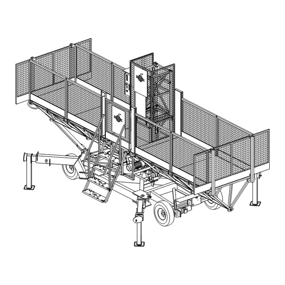
The platform can be adjusted to suit the required working situation with the use of separate platform elements. The width of the platform can be adjusted by means of outriggers. Fig.2-1 Basic set MSHF chassis/ground frame MSHF • 7295-026A... - Page 26 The simple construction ensures that only a minimum of maintenance is required. The mast elements, the chassis, the drive unit, the cable guides and various other components are protected from corrosion by an appropriate surface treatment. MSHF • 7295-026A...
-
Page 27: Safety
- If the LOWER limit switch fails to the path of the machine. operate, so that the mast climbing work platform continues to descend, an During use, no person should additional emergency LOWER limit stand under the machine. switch is operated. MSHF • 7295-026A... - Page 28 The power supply must be carried out as given in this instruction switched off and the connector manual. withdrawn from the supply socket. - During assembly and maintenance, the mast climbing work platform may not be used for other purposes. MSHF • 7295-026A...
-
Page 29: Safety After Use
3.5 Built-in and additional safety features The MSHF mast climbing work platform is provided with the following in-built and additional safety features: - Phase control relay in the control box. - "Emergency stop" push button on every control box. - Page 30 SAFETY MSHF • 7295-026A...
-
Page 31: Transport
Disassemble the machine before A Lifting point, for drive unit only! transporting it as described in chapter 8. B Support points for the fork of a fork-lift truck. For the transport dimensions, see chapter 1. Fig.4-1 Transport MSHF MSHF • 7295-026A... -
Page 32: Repositioning On The Building Site
The maximum speed at which the chassis may be towed behind a vehicle is 30 m/ min / 98.4 ft/min. Exceeding this speed can cause serious damage to the motor. Fig.4-3 Brake lever chassis MSHF • 7295-026A... -
Page 33: Chassis Drive Unit
Fig.4-4 Switch box chassis pushing the emergency push-button. After the chassis has been repositioned, the red push-button must be pressed and the connectors for the power supply and controls withdrawn. Fig.4-5 Control box chassis MSHF • 7295-026A... -
Page 34: Repositioning With A Crane
No. of plug-in fences 150 x 18 kg / 40 lb No. of head fences x 30 kg / 66 lb No. of corner posts x 6,5 kg / 14 lb Total transport weight kg / lb MSHF • 7295-026A... -
Page 35: Control Components
5.2 Power supply socket for the chassis Fig.5-1 Power supply socket drive unit The power supply cable for the electrical supply between the building site connection and the chassis must be connected to the socket. Fig.5-2 Power supply socket chassis MSHF • 7295-026A... -
Page 36: Platform Control Box
The main switch can be secured with a padlock to prevent unauthorized use of the platform. The following components are mounted in the control box: -the main switch -the safety relay -the control relay -the transformer -the automatic fuses MSHF • 7295-026A... -
Page 37: Assembly And Anchoring
The loading of the mast climbing work platform must be planned so that when, in the assembly situation, the maximum height of the mast above the last anchor is reached (the maximum distance between anchors), the material load on the platform is a minimum. MSHF • 7295-026A... -
Page 38: Preparation For Assembly
- The electrical power supply connection must be placed as close to the mast climbing work platform as possible so as to reduce the voltage drop to a minimum. If the voltage reduction is too great the machine may not function correctly. MSHF • 7295-026A... -
Page 39: Ground Support
Fig.6-2 Ground support chassis deformation. If the machine is installed on a concrete foundation or on a hard road surface, the installation must be provided with wooden packing to prevent slipping. Fig.6-3 Ground support ground frame MSHF • 7295-026A... -
Page 40: Positioning The Mast Climbing Work Platform
- single mast, freestanding (chassis mounted) Fig.6-4 Distance to the facade - single mast, anchored (chassis or ground frame mounted) - two masts, freestanding (chassis mounted) - two masts, anchored (chassis or ground frame mounted). MSHF • 7295-026A... -
Page 41: Mast Climbing Work Platform With Single Mast On A Chassis
Fig.6-6 Autolevel locking pin Tighten the platform bolts until the specified torque is applied. The width of the platform can be adjusted to fit the form of the façade. See section 6.6. Fig.6-7 Lower striker plate MSHF • 7295-026A... -
Page 42: Mast Climbing Work Platform With One Mast On A Ground Frame
(with a length of at least 1 metre / 40 inch) placed against two adjacent sides of the mast. Place wooden packing under the machine to provide optimum load spreading and stability. Fig.6-10 Fence Fig.6-8 Lower striker plate Fig.6-11 Gate safety switch MSHF • 7295-026A... - Page 43 Mount the fencing and secure it with "hairpins". 10. Mount the gate and the cam for the gate safety switch. The roller must fall into the cam when the gate is closed. Fig.6-14 Fence Fig.6-12 Step Fig.6-15 Gate safety switch MSHF • 7295-026A...
-
Page 44: Mast Climbing Work Platform With Two Masts On A Chassis
1 meter / 40 inch. Fig.6-17 Autolevel locking pin Check that the autolevel locking pins and the lower striker plates are mounted on both chassis. Fig.6-18 Lower striker plate MSHF • 7295-026A... - Page 45 The width of the platform can be adjusted to fit the form of the façade. See section 6.6. 12. Mount the steps and secure them with locking pins. 13. Mount the fencing and secure it with "hairpins". Fig.6-20 Fence Fig.6-19 Step MSHF • 7295-026A...
- Page 46 17. Connect the control cable and the electrical power supply cable. Secure the cables to the underside of the platform neatly so that they do not hang down. Fig.6-22 Autolevel locking pin Fig.6-23 Control cable dummy plug 6-10 MSHF • 7295-026A...
-
Page 47: Mast Climbing Work Platform With Two Masts On Ground Frames
The platform may not exceed the maximum length. Tighten the platform bolts until the specified torque is applied. Assemble the second ground frame to the first by fixing the platform Fig.6-25 Lower striker plate elements together. MSHF • 7295-026A 6-11... - Page 48 11. Mount the fencing and secure it with "hairpins". 12. Mount the gate and the cam for the gate safety switch. The roller must fall into the cam when the gate is closed. Fig.6-27 Step Fig.6-26 Gate safety switch Fig.6-28 Fence 6-12 MSHF • 7295-026A...
- Page 49 15. Connect the control cable and the electrical power supply cable. Secure the cables to the underside of the platform neatly so that they do not hang down. Fig.6-29 Autolevel locking pin Fig.6-30 Control cable dummy plug MSHF • 7295-026A 6-13...
-
Page 50: Assembly Of The Mast
02 and the phaselight on the phaseguard relay does not burn, set Fig.6-31 Power supply the main switch in the other position. The display must show code 00 and the phase light will be burning. Fig.6-32 Main switch 6-14 MSHF • 7295-026A... - Page 51 Stand on the platform and use the crane to place a mast element on the last element assembled. Secure the Fig.6-34 Proximity switch mast element with four bolts, washers and nuts. Tighten the bolts to the specified torque value. (See chapter 1) MSHF • 7295-026A 6-15...
- Page 52 13. Assemble the mast cover panels from the platform and secure them. 14. The assembly is now complete. The assembly must now be tested as described in section 7.1 Fig.6-36 Mast cover 6-16 MSHF • 7295-026A...
-
Page 53: Anchoring The Mast
Recheck as each anchor is secured. The mast must be anchored to the building at the distances specified in the table in chapter 1. The anchors are assembled from mast adapters, horizontal anchor tubes and a support tube. MSHF • 7295-026A 6-17... - Page 54 - Specifications for these types of bolts are available from the supplier. Permission to use them must be obtained from the local authorities. 6-18 MSHF • 7295-026A...
-
Page 55: Adjusting The Platform Width
The planks used for adjusting the platform must in every case be secured in every direction. The platform widening and the mast anchors must not come into contact when the platform is raised and lowered. MSHF • 7295-026A 6-19... - Page 56 Cover the outriggers with planks. Fig.6-38 Outrigger platform extension Fix cross strips with a right-angle profile to the underside of the planking and secure them to the outriggers. Mount the anchor ramp to the outriggers. Fig.6-39 Anchor ramp 6-20 MSHF • 7295-026A...
-
Page 57: Setting The Machine Left Or Right
(left or right). Fig.6-40 Machine setting left Set the switch on the control box in the required position (left or right). Fig.6-41 machine setting right Fig.6-42 switch left/right setting MSHF • 7295-026A 6-21... -
Page 58: Checking And Adjusting The Lower Striker Plates
If the lower striker plate does not touch the limit switch, adjust the position of the striker plate until it just touches the limit switch. Check the adjustment. Fig.6-43 Adjusting lower striker plate 6-22 MSHF • 7295-026A... -
Page 59: Checking The Autolevel Switches
Operate the "UP" push-button on the platform. The lowest unit must now be Fig.6-44 Brake lever drive unit the first to rise. Repeat the previous steps for the other unit. If necessary, adjust the switches. Fig.6-45 Autolevel switches MSHF • 7295-026A 6-23... -
Page 60: Adjusting The Emos System
DIN VDE 0185, part II, §5.2 The cable supplied (25 mm² / 0.0039 in² cross section, 25 m / 82 ft long) must be connected to the terminal box on the building site. Fig.6-47 Lightning protection 6-24 MSHF • 7295-026A... -
Page 61: Operation
(daily if it is used every day) for: - anchors and cable guides - presence of all security devices - connection between mast elements - position of the masts - any loose components MSHF • 7295-026A... - Page 62 Only single-mast. Eccentric overload Fig.7-2 Emergency push-button check: During a few seconds there will be sounding a buzzer and a light will flash on the control box. MSHF • 7295-026A...
-
Page 63: Testing
Release the brake on one of the motors by pulling the lever on the motor. The platform may not descend. Release the brake lever. Release the other brake. The platform should not descend. Release the brake lever. Fig.7-3 Brake lever drive unit MSHF • 7295-026A... -
Page 64: Operation From The Platform
- Using the malfunction analysis in chapter 10, try to solve the problem. If the problem can not be solved it is possible to make a emergency descent in the following way. MSHF • 7295-026A... - Page 65 If the platform becomes excessively inclined, the autolevel safety system will come into operation. In this event, external help will be required. MSHF • 7295-026A...
-
Page 66: Eccentric Overload Device
OPERATION 7.7 Eccentric overload device The MSHF mast climbing work platform is provided with an eccentric overload device. The eccentric overload device is only active in a single-mast construction. When the platform is eccentric overloaded to 90%, the light on top of the control box starts to burn. -
Page 67: Disassembly And Transport
Repeat this procedure until the mast, with the platform in its lowest position, has been completely disassembled. Release the brakes and allow the platform to descend onto the buffers. Fig.8-1 Drive unit brake release MSHF • 7295-026A... - Page 68 11. Disassemble the fences, the gates and the gate posts. 12. Disassemble the platform extensions. Slide in the outriggers Fig.8-3 Control cable dummy plug and secure them. Fig.8-4 Securing outrigger MSHF • 7295-026A...
- Page 69 Support the platform if necessary. 14. The platform elements can be packed in bundles of five. 15. Slide in the outriggers of the chassis and secure them. Fig.8-5 Bundle platform elements Fig.8-6 Locking pin outrigger MSHF • 7295-026A...
- Page 70 DISASSEMBLY AND TRANSPORT MSHF • 7295-026A...
-
Page 71: Maintenance
This will guarantee a long working life for the mast climbing work platform. Parts must comply with to the technical specification of Hek Manufacturing b.v.! Use only original parts of Hek Manufacturing b.v. - Page 72 - Cover the basic machine with a tarpaulin; in every case, cover the control boxes and the limit switches. - Screw out the jack of the chassis so that it does not rest on its wheels. - For long-term storage, consult your dealer. MSHF • 7295-026A...
-
Page 73: Autolevel Mechanism Check
(n = 0 rev./min). The braking effect is achieved by friction between several discs and the brake must be used "dry" (not greased). MSHF • 7295-026A... - Page 74 MSHF • 7295-026A...
- Page 75 (6). Remove the rubber dust ring and use a vernier calliper gauge to measure the thickness of the rotor. Replace the rotor if the thickness is 9.5 mm / 0.37 in or less. Fig.9-3 Motorbrake MSHF • 7295-026A...
- Page 76 0.3 mm / 0.012 in wide. The adjustment of the hand release may not be changed, not even when air gap "a" is readjusted, as security can be adversely affected. Mount the rubber dustring, the fan cover and the brake lever. MSHF • 7295-026A...
-
Page 77: Malfunction Analysis
- Switch defective electrician L/R malfunction - Fuse F104 deactivated - Set machines Left and Right, activate fuse F104 In all cases not covered by the above malfunction tables an electrician must be consulted. MSHF • 7295-026A 10-1... - Page 78 - Minimum mast distance too little erratically The platform does not - Inform your technical service or dealer develop sufficient power In all cases not covered by the above malfunction tables an electrician must be consulted. 10-2 MSHF • 7295-026A...
-
Page 79: Machine Disposal
- Demolition. Discarding the machine - Drain the oil out of the reduction gearbox and dispose of this via an authorized facility. - Remove any usable parts. - Dispose of the remainder via waste disposal facility. MSHF • 7295-026A 11-1... - Page 80 MACHINE DISPOSAL 11-2 MSHF • 7295-026A...
-
Page 81: List Of Keywords
Push button DOWN Push button UP Fencing 6-4, 6-6, 6-7, 6-9, 6-12, 6-20 Foreword Reaction force Repositioning on the building site Repositioning with a crane Gate safety switch 6-6, 6-7, 6-10, 6-12 Ground pressure Ground support MSHF • 7295-026A 12-1... - Page 82 Safety Safety after use Safety in use Safety prior to use Scaffold coupling 1-14 Setting the machine left or right 6-21 Signal light Special situations Symbols Symmetrical platform construction Testing Top element 6-16 Transport Transport weight 12-2 MSHF • 7295-026A...
-
Page 83: Appendices
APPENDICES MSHF • 7295-026A... - Page 84 APPENDICES MSHF • 7295-026A...
Need help?
Do you have a question about the MSHF and is the answer not in the manual?
Questions and answers