Table of Contents
Advertisement
Quick Links
Hi-Target Surveying Instrument Co. Ltd.
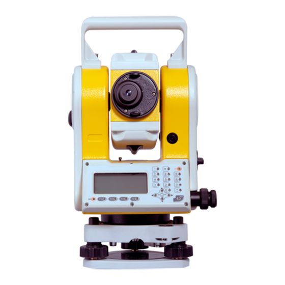
NAME: TOTALSTATION
MODEL:ZTS-360R
The statements should be displayed in the user manual:
changes or modifications not expressly approved by the
party responsible for compliance could void the user's authority
to operate the equipment.
This equipment has been tested and found to comply with
the limits for a Class B digital device, pursuant to Part 15 of the
FCC Rules. These limits are designed to provide reasonable
protection against harmful interference in a residential
installation. This equipment generates, uses and can radiate radio
frequency energy and, if not installed and used in accordance
with the instructions, may cause harmful interference to radio
communications.However, there is no guarantee that interference
will not occur in a particular installation.
If this equipment does cause harmful interference to radio
or television reception, which can be determined by turning the
equipment off and on, the user is encouraged to try to correct the
interference by one or more of the
following measures:
-- Reorient or relocate the receiving antenna.
-- Increase the separation between the equipment and
receiver.
-- Connect the equipment into an outlet on a circuit
different from that to which the receiver is connected.
-- Consult the dealer or an experienced radio/TV technician
for help.
Advertisement
Table of Contents

Summary of Contents for Hi-Target Surveying Instrument ZTS-360R
- Page 1 Hi-Target Surveying Instrument Co. Ltd. NAME: TOTALSTATION MODEL:ZTS-360R The statements should be displayed in the user manual: changes or modifications not expressly approved by the party responsible for compliance could void the user’s authority to operate the equipment. This equipment has been tested and found to comply with the limits for a Class B digital device, pursuant to Part 15 of the FCC Rules.
- Page 2 Preface Thank you for purchasing our ZTS-360 Mini series total station! This manual is your good helper, please read it before operating the instrument and keep it properly. Product Validation In order to get our best service, please give the feedback about the version, number, purchasing date of the instrument and your valuable suggestions to us after you purchase our product.
- Page 3 Features Rich Features--our total station carries abundant surveying application, at the same time has the functions of data storage, parameter settings and etc. It’s suitable for all kinds of professional measurements. Absolute code disc Equipped with absolute code disc, the instrument can measure after switched on .Even if reset the battery halfway, the azimuth information will not be lost.
- Page 4 Laser plummet Easy to direct the station point and free station Notice: Don’t look directly into the sun with the objective lens; Do not leave the instrument at extreme temperatures (too high or too low) or use it when thermal shock; When you don’t use the instrument, should load it in the box and place it well-ventilate and dry place,and pay attention to the shock-proof ,dust-proof and damp-proof;...
- Page 5 and put it in ventilated place for a period time to make the equipment fully dry before using and packing. Please check out that the indicators, functions, power supply, initial setting and correction parameters of the instrument meet the requirements before operating. If discovering the abnormal function of the instrument, non-professional maintenance personnel are not allowed to disassemble the instrument without authorization, in case of any...
- Page 6 measurement signal. Warnings: It’s dangerous to use Class 3R Laser instrument improperly. Precautions: In order to avoid causing damage, the proper precautions should be taken for you and control well the distance (in accordance with the standard “IEC60825-1:2001”) that may occur hazards.
- Page 7 *The hazardous distance refers to the maximum distance which is from beginning of the laser beams to the laser beam weaken until it does not harm people. The built-in rangefinder products equipped with Class 3R/IIIa laser whose hazardous distance is 1000 meters (3300feet),and in the distance, the strength weakens to a Class 1 laser (sightseeing beam eyes couldn't hurt).
-
Page 8: Table Of Contents
Content 1. Use of instrument.............. 1 2. Names and functions of the components ....2 2.1 Names of the components ........... 2 2.2 The information of the displays ........ 4 2.3 Functional keys under the basic measurement mode ..................... 9 2.3.1 Angle mode (including three pages) .. - Page 9 Multiplying Constant ..............21 3.12 Selecting Data File ............22 4. Preparations before measurements ......23 4.1 Unpacking and storing instruments......23 4.2 Set up the instrument ..........23 4.2.1 Using plummets to center and level (align) .....................23 4.2.2 Using centering device to center ....25 4.3 Loading and unloading of battery ......26 4.4 Reflecting Prism.
- Page 10 7. Coordinate mode ............. 41 8. Offset mode ............... 46 8.1 Offset (Angle) ..............46 8.2 Offset (Dist1) ..............47 8.3 Offset (Dist2) ..............49 8.4 Offset (Plane) ..............50 8.5 Offset (Column) .............52 9. Menu ..................55 9.1 Surveying .................55 9.1.1 Operation ............55 9.1.2 Preparation ............56 9.1.2.1 File selection for surveying ......56 9.1.2.2 Select coordinate file ........56...
- Page 11 9.3.5 Information of disk (MenInfo) ....84 9.3.6 Update ..............84 9.4 Program ................87 9.4.1 Remote height (REM) ........87 9.4.1.1 “Input T.H” Mode .........87 9.4.1.2 “Without T.H” ..........88 9.4.2 MLM ..............90 9.4.3 Coord.Z ..............91 9.4.4 Area measurement .........93 9.4.5 Projection ............94 9.4.6 Roadway .............96 9.5 Options ................96 9.6 Adjust ................97 9.6.1 Calibrate I.E ............98...
- Page 12 11. Adjustments and Corrections ........ 113 11.1 Tubular Level ............113 11.2 Circular Level ............114 11.3 Reticle of the telescope .......... 114 11.4 The Perpendicularity of Collimation axis and Cross axis (2C) ................115 11.5 Vertical plate index zero automatic compensation ................
-
Page 13: Use Of Instrument
1. Use of instrument The total station is such an instrument that measures the azimuth and distances to destination and can calculate the destination point coordinates automatically. It plays an important role in the economic construction and national defense construction. General Survey, exploration and mining of minerals, the construction of railways, roads, bridges, irrigation, urban planning and construction is driven by electronic total station measurements. -
Page 14: Names And Functions Of The Components
2. Names and functions of the components 2.1 Names of the components Handle Coarse sighting device Number Battery box Horizontal Display clamping screw Horizontal tangent screw Circular bubble Leveling screw Base... - Page 15 Handle Objective lens Vertical clamping screw USB port Vertical tangent screw Fast measuring key Display RS-232 Communication port Leveling screw Base...
-
Page 16: The Information Of The Displays
2.2 The information of the displays The sketch of display and keyboard in face left The sketch of display and keyboard in face right... - Page 17 Symbols on the keyboard Keys Name Function In the basic interface , enter the angle Angle measurement . Under other modes, move measurement the cursor up or up to select the options. In the basic interface,enter the distance Distance mode; DIST measurement In the other modes,Move the Cursor down...
- Page 18 the basic measurement interface. End the dialogue box without saving the Exit /quit input,and return to the previous step change the option in the select box ◄► Left /right Data list page Move the Cursor up and down in order. ▲▼...
- Page 19 distance difference. Elevation difference. dVD is to stake out difference between elevation differences. Slope distance. dSD is to stake out differences between slope distances. Northing. dN is to stake out differences between north-coordinates. Easting. dE is to stake out differences between East-coordinates.
- Page 20 inserter goes to the next column. If there’s only one or no edited column in the dialogue box, the soft key ‘Enter’ is also used to accept the input and exit the dialogue box. Input Go to Coordinate dialogue box and enter the coordinates with keyboard M.Pt Retrieval coordinates of points from measured file...
-
Page 21: Functional Keys Under The Basic Measurement Mode
2.3 Functional keys under the basic measurement mode 2.3.1 Angle mode (including three pages) 278°12′23″ 278°12′23″ [F4] 159°54′05″ 159°54′05″ Save 0set Hset Hold [F4] 278°12′23″ [F4] 159°54′05″ H-Bz Vmode Page Soft key Reference Function Record the measured Save angle to the selected file. Set the horizontal angle 0set as 0°... -
Page 22: Distance Measurement Mode
Switch between Vertical angle and slop Display the third page of the soft key functions Set the beep on or off H-Bz when the horizontal angle is 0°, 90°,180°,270° Switch between HR (horizontal right/ clockwise) and HL (horizontal left/ anticlockwise) mode Vertical Angle Mode (altitude angle(Vh), Zenith (Vz)... - Page 23 Page Soft key Reference Function Start distance measurement and Save record the measured data into the selected files (measurement file ‘File(.MEA)’ and coordinate file ‘File(.COO)’are selected in surveying function or by star key). Start Distance Mode Meas Switch between four distance Mode measurement mode (single accurate measuring (sngl)/ repeated accurate...
-
Page 24: Coordinate Measurement Mode
2.3.3 Coordinate measurement mode 278°12′23″ 278°12′23″ 159°54′05″ 159°54′05″ [F4] Save Meas Mode Config 278°12′23″ [F4] 159°54′05″ [F4] Ofset Aver. Page Soft key Reference Function Start coordinate measurement and record Save the measured data into the selected files (measurement file ‘File(.MEA)’ or coordinate file ‘File(.COO)’... -
Page 25: Explanation Of Saving Data
Set coordinates for station Display the third page of the soft key P2/3 functions Start offset measurement (eccentric Ofset measurement) Stake out coordinates Set the times of average measurement Aver. Display the first page of the soft key functions 2.3.4 Explanation of saving data If you have never selected the measurement file and your first time to use the [Save] soft key, a dialogue box of ‘Select file’... - Page 26 ▶ Reflect : Contrast: ☼ [☆] select file Light Tilt Laser Para. Settings from the star key(★) are as followed: ● Adjust contrast : press [▲] and [▼]; ● Adjust background light of the screen : press [F4] to open the backlight ,then press [◄] to adjust light; ●...
- Page 27 Temp.: ℃ 1013 Press: Prism c: PPM: Signal Clear Signal Enter...
-
Page 28: Initial Setup
3. Initial setup 3.1 On & Off Press the power key until the screen displays pictures. The instrument is now switched on. After self-checking, the instrument enters Angle Mode automatically (see Angle Mode for details) Pressing power key will leads to a dialogue box. Press [ENT] to turn off the instrument. -
Page 29: Set Up The Target Type
jitter and stop measuring .You can turn off the compensator by the using star key(★) functions. 3.3 Set up the target Type Our series total station has three reflectors to be selected, which are prism, non-prism (NP) and reflect board (RB). You can set by job. -
Page 30: Set Up The Atmospheric Correction
Continuing with the explained operation in 3.4, you may press [Signal] and the intensity of signal is displayed in the ‘Signal’ column above. The minimum measurable intensity should be 1. Being less than 1 indicates that the target cannot be aimed and measured. -
Page 31: Calculate The Atmospheric Correction Out With Temperature And Pressure Sensor
operations in 3.5, press soft key [Enter] to move inserter down to the ‘PPM’ column to enter the value. Temp.: ℃ Temp.: ℃ Press: 1013 1013 Press: Prism c: Prism c: PPM: PPM: Signal Signal Clear Signal Enter Signal Enter Clear 3.6.2 Calculate the Atmospheric Correction out with temperature and pressure sensor... -
Page 32: Set Up The Minimum Reading Of The Angle
The formulas of two corrections about our instrument are as followed: Corrected Horizontal Distance : D=S×[cosα+sinα×S×cosα(K-2) / 2Re] Corrected Elevation : H=S×[sinα+cosα×S×cosα(1-K) / 2Re] If the Atmospheric Refraction and the earth curvature are not corrected, the formula for calculating horizontal distance and elevation are as followed: D=S×cosα... -
Page 33: Set Rectangle Beep
Auto shut off [ 1. Never 5minutes 10minutes 10minutes Exit Enter You may choose ‘Never’ to cancel the auto shutdown. When choosing 5, 10, 20 minutes opts, the instrument will shut down automatically if there is no key pressed. Use the [▲] or [▼] keys to move indicator ‘[]’... -
Page 34: Selecting Data File
3.12 Selecting Data File The instrument needs large data and creates large data when it is operated. This data needs to be storied in the system files of the instrument as a file form. It’s a good habit that selecting the measuring working files before working. -
Page 35: Preparations Before Measurements
4. Preparations before measurements 4.1 Unpacking and storing instruments Unpacking Lay down the box gently with the top side facing up. Open the lock and take out the instrument. Storage Cover the telescope cover. Make sure that the vertical clamping screw and the level bubble face upwards. Lay down the instrument into the box (with objective lens of the telescope facing downwards.). - Page 36 bottom of the unit to make sure it is secured to the tripod. Using the circular level to level the instrument coarsely ① Twist and adjust the two leveling screw A and B on the bottom of the instrument until the bubbles of the circular level moves to the line perpendicular to the center line the screw A and B;...
-
Page 37: Using Centering Device To Center
Screw C Screw B Screw A ③ Turn around the instrument 90° again. Repeat above steps until the bubble remains in the center of the plate level even though the instrument is rotated to any position. 4.2.2 Using centering device to center Set up the tripod;... -
Page 38: Loading And Unloading Of Battery
instrument aims at the station precisely. Repeat the steps above until the instrument aims at the station precisely. 4.3 Loading and unloading of battery The information of the battery --Full battery, operation is available. --Just appearing this information which means the battery can support the instrument for another 4 hours. -
Page 39: Reflecting Prism
and +45℃. Charging process may be abnormal if being over the temperature range. ▲A battery can be recharged for 300-500 times. ▲A monthly recharging is required if the instrument is not used for a long time. 4.4 Reflecting Prism. When measuring distance with prism mode, a reflecting prism must be set at the target site. -
Page 40: Entering Letters And Numbers
Aim at the target with the cross center in the coarse sighting device on the top of the lens. Your eyes should keep a proper distance (about 200mm) away from the sighting device; Obtain a sharp image of the target on the reticule with the focusing screw. - Page 41 then press [1] again, “SS”displays in the edit box; Press [1] again, “ST”displays in the edit box; The interval of pressing the key [1] twice is not over 0.4 seconds .If over, you can press [▲] or [▼] to correct it; Select file(.MEA&.COO) Select file(.MEA&.COO) Select file(.MEA&.COO)
- Page 42 Station Clear Pt.n Enter The order of the keys:[-]→[1]→[2]→[3]→[.]→[4] →[5] →[6] ; The result is shown below: Station -123.456 Clear Pt.n Enter Of cause, you can input “-” finally to complete the input; After completing the input, press [ENT] to record the input and end the edit box;...
-
Page 43: Notice For Using U Disk
Set HA 123.4556 Clear Exit Enter After completing the input, press [F4] to confirm the input or press [ESC] to cancel it. If it is over “360°”, a prompt box will appear “Overtop!”. 4.9 Notice for using U disk When running the program, don’t insert or pull out the U disk. -
Page 44: Angle Mode
5. Angle mode The instrument would enter the Angle Mode automatically after switched on. You can also enter this Mode by pressing [ANG] under basic measurement mode. This Mode involves three pages switched by the key [F4]. Their functions are explained as followed: 278°12′23″... -
Page 45: 0Set
● The number of point name in the system is added 1 automatically. If you want to modify point mane, code, and target height, just press [Num.] or [Alph.], if don’t just press [ENT] to save. The system saves the record with a prompt “Finished”, ●... -
Page 46: Hold
5.4 Hold Function: Another method to set horizontal angle. ● Turn around the alidade to the wanted horizontal angle and press soft key [Hold], the turn around the alidade a and the readout of horizontal angle is ‘hold’ and not changing with turning the alidade again, the horizontal angle remain the same. - Page 47 Count 90°00′00″ 90°00′00″ Oset Exit Hold Count: The times of the measurement; Ht: The sum of angle; Hm: The average value of angle Aim at point ‘A’, then press [F1] (0 set); ● REP-Angle Set 0? ● Press [F4](Yes); Count [ 0] 00°00′00″...
-
Page 48: Slope (V%)
Count [ 1] 120°20′00″ 120°20′00″ 120°09′30″ Oset Exit Hold Aim at point ‘B’ again by horizontal motion and ● tangent screw and press [F3](Hold); Count [ 2] 240°40′00″ 120°20′00″ 120°18′00″ Oset Exit Rel. ● Repeat the steps above until the measurement times wanted;... -
Page 49: L/R
5.8 L/R Press [F2] to make the horizontal angle mode switched between right angle (HR) and left angle (HL). HR: Right angle mode .When the alidade is rotated clockwise, the horizon angle is increscent; HL: Left angle mode. When the alidade is rotated anticlockwise, the horizon angle is decreasing. -
Page 50: Distance Mode
6. Distance mode Press [DIST] to enter the distance measurement mode, which has two interfaces . The functions of first interface are “Save”, “Meas.” and “Mode”; The functions of the second interface are “Ofset”, “S.O” and “m/f/i”. The two interfaces shown as below: 278°12′23″... -
Page 51: Mode
6.3 Mode This function is used for the work mode of EDM. These modes are “Single”, “Rept”, “Cont”, “Track”. EDM Mode [ 1. Single Rept. Cont Track Exit Enter Press [▲] or [▼] to move the “[]” the wanted option , then press [ENT] to save. - Page 52 dhd: is to stake out the difference between horizontal distance measured and it expected . A positive result indicates that the measured horizontal distance is greater than the expectation value. The lens should be moved to the instrument. dvd: is to stake out the difference between elevation difference measured and it expected.
-
Page 53: Coordinate Mode
7. Coordinate mode Press [CORD] to enter the coordinate measurement mode. According to the diagram below, please set up the coordinates station, azimuth, target height and instrument height before coordinate measurement. Center of lens Center of instrument Coordinates of unknown point (N1,B1,Z1) Coordinates of the center of instrument =NC,BC,ZC+... - Page 54 278°12′23″ 278°12′23″ 159°54′05″ 159°54′05″ [F4] Save Meas Mode Config 278°12′23″ [F4] 159°54′05″ [F4] Ofset Aver. Save:After press [F1], the interface of “Information” ● appears (if you haven’t select measured file, there will be a interface of “Select file (.MEA)” to let you select file.), which needs you the point name (Pt.N) ,Code and target height (T.H).
- Page 55 them, or [ESC] to exit the input interface. If you want to view instrument and target height, just refer to this operation. The input interface is as shown below: I.H&T.H I.H: 1.59 1.68 T.H: Clear Enter The range of instrument height and target height is “± 999.999”.
- Page 56 already done under Angle Mode, you don’t need to set BBS again under Coordinate Mode. 100.000 NBS: 200.213 EBS: ZBS: 1.123 Clear List Enter There are two way to get backsight coordinates, which are inputting by keyboard and retrieving from files; If you select inputting, just input by keyboard.
- Page 57 staking-out function. With this function, you may put designed data onto earth points. See reference in “9.2 Staking out”; ● Aver.: In the third interface, press [F3] to set the times of measurement.
-
Page 58: Offset Mode
8. Offset mode It includes five functions which are “Offset(Angle)”, “Offset(Dist1)”,“Offset(Dist2)”,“Offset(Plane)”,“Offset(Column )”. These functions help for coordinate measurement, and can get the coordinates of the point which the prism can’t be at. Before operating these functions, please set ‘STA’, orientation, instrument height and target height. -
Page 59: Offset (Dist1)
Offset(Angle)-Prism HR: 200°54′21″ SD: HD: VD: Meas Mode If you want to re-input the target height, press [T.H] to re-input. Press [Meas] to start measurement. After measuring, press [Enter] to enter the interface of “Offset (angle)-Result”: Offset(Angle)-Result 200°54′21″ SD: 11.775 HD:... - Page 60 Horizontal distance on the left or right Target height Prism P Instrument center Station The diagram of angle offset In the menu of “Offset”, select “2. Offset (Dist1)” to enter the interface of “Distance”: Distance Left (-) /Right(+) OSD: Front (-) /Behind(+)OSD: Clear Enter The relation between “+”...
-
Page 61: Offset (Dist2)
Offset (dist1)-Result HR: 200°54′21″ N: -10.998 E: -4.201 Z: 0.190 Next P Save Display the coordinates or offset point. Pressing [Next P] to measure next point; press [Save] to save the coordinates of offset point; press [ESC] to exit. 8.3 Offset (Dist2) It is specifically useful when the measured point is exactly on the line of the two measurable points, as well as the distance between measured point and the two measuring point is known. -
Page 62: Offset (Plane)
Offset (Dist2) Distance: Clear Enter Input the distance, and press [Enter] to enter the interface of “Offset -Begin”. You must aim at point “P0” to measure.After measuring, press [ENT] to exit the interface to enter the interface of “Offset-End”. Offset-Begin Offset-End 171°49′54″... - Page 63 define the measured plane. Then, you can aim at the measuring point ‘P0’, and the instrument will calculate and display the coordinate of intersection of the defined plane and the collimation axis. i.e the coordinate of “P0”. Mention that the target height under this mode must be zero.
-
Page 64: Offset (Column)
Now turn around the alidade to aim at the offset point. Mention that the offset point must be on the defined plane but not below the prism bar, otherwise the result will not be correct. The value of coordinate is being refreshed in process of aiming. Press [Next P] to enter the offset measurement of next point and press [Save] to record the result. - Page 65 Offset (Column)-Prism HR: 181°14′01″ SD: HD: VD: Meas Mode After measuring→ Offset (Column)-Prism HR: 181° 14′01″ SD: 4.570 HD: 4.575 VD: 1.004 Meas Mode If you want to point ‘P0’, please input its height as zero before measuring it. If you want to measure “P0’”, input the real height value, then press [Meas] to start measure.
- Page 66 Offset(column)-Center 179°59′39″ -4.663 -0.117 1.004 Next P Save Press [Next P] to enter the next offset, measurement. Press [Save] to exit.
-
Page 67: Menu
9. Menu In the basic measurement interface, press [MENU] to enter the menu interface, then, press [F4] to enter the next page. Menu Menu 1.Adjust 1.Surveying 2.Stake 2.Config [F4] 3.Select CodeFile 3.Fileman 4.Grid scale 4.Program 5.Options 5.Communication On the every page of menu, you can press number key to select. -
Page 68: Preparation
2) Select coordinate file for retrieving data and saving the surveyed data; 3) Set station including name, coordinate and instrument height; 4) Set backsight by measuring backsight or azimuth angle. 5) Set the target height of measured point and start to survey and save data. -
Page 69: Station And Backsight
specified file. The coordinate file selection is as below: Surveying Surveying 1.Station 1. Select file 2.Setup BBS 2. Survey Config [F4] 3.Meas Select file Select file (.COO) 1.File(.MEA) 2.File(.COO) File: 3.File(.COO) 4.Linear file List Num. Enter Refer to “9.1.2.1 File selection for surveying”. 9.1.3 Station and backsight The station and orientation of backsight point in the surveying mode and coordinate measurement mode is common. - Page 70 Setup STA STA-> Code: 1.000 I.H: Input Search Save 2) Press the key [F4](STA); Surveying Setup STA Pt.n: Input List Coord. Enter 3) Press [F1](Input); Surveying Setup STA Pt.n: Num. Enter 4) Input point name, and press [F4]; Set STA 100.000 100.000 10.000...
- Page 71 Setup STA STA-> Code: 1.000 I.H: Input Search Save 6) Press [▼] to move the “->” to “Code” column; Setup STA STA: Code-> 1.000 I.H: Input List Save 7) Press [F1] to input code , then press [F4] to confirm it; Setup STA STA: TREE...
-
Page 72: Example For Setting Angle
10) Press [F4](Yes) to finish setting station; 9.1.3.2 Example for setting angle The azimuth angle must be confirmed by measuring. You can save the data of orientation angle of backsight point by the following method. 1) Enter the interface of “BBS”; Setup BSS BBS->... - Page 73 5) The system checks the current coordinate file, if checks it ,then display the coordinates and you can press [F4]; Setup BSS BBS-> Code: 1.000 I.H: Input Search Meas 6) Input “Code” and target height “T.H”; Setup BSS BBS: Code-> 1.000 I.H:...
-
Page 74: 4Measurement
9.1.4Measurement 1) In the first page of surveying, press [3] to enter the interface of “Meas”; Surveying Meas 1.Station Pt.n-> 2.Setup BSS Code: 3.Meas 1.000 T.H: Input Search Meas Ditto 2) Press [F1](Input) to input the measurement point name ,then press [Enter] to input code; Meas Meas Pt.n->... -
Page 75: Staking Out
For example, press [F2](Dist) to start measuring; 90°12′22″ 200°54′24″ [Sgnl]<< >Measuring... 6) After finishing measuring, press [F4](Yes) with data saved; 90°12′22″ 200°54′24″ 17.245 17.125 -1.523 >Enter? 7) The point name will be added one, and you can measure next point. You can input name ,code and target height as the same way and measure as the same way of last point by pressing [F4](Ditto) or you can press [F3] to select the measurement methods;... -
Page 76: Staking Out Points
1.Setup STA 1.PolarCoord.Meas [F4] 2. Setup BBS 2.Resection 3. Stake out The ‘Setup STA’ and ‘Setup BBS’ are the preparation work for staking out. If you have already setup them, re-setting them are not necessary. 9.2.1 Staking out points Two methods for staking out to be selected: 1) Retrieve the coordinates in the memory by point nane;... - Page 77 Stake out -1.015 -3.311 0.320 > Enter? 4) Input the target height; 5) After setting the stake-out point, you can start to stake out. Stake out-Calc HR: 252°23′52″ HD: 3.473 m Dist Coord. HR:The calculated angle of tak-outpoint HD: the calculated distance from instrument to stake-out point;...
- Page 78 7) Rotate the instrument to make the “dHR” as about 0° , then lock the horizontal motion screw and use horizontal tangent screw to make the “dHR” as “0°00′00″”. Finally, press[F1] (Meas); 252°23′52″ 252°23′52″ 0°00′00″ 0°00′00″ dHR: dHR: [Sngl]<< [Sngl]<< dHD: Meas Mode...
-
Page 79: Polar Coordinates
Stake out Pt.n: List Num. Enter 9.2.2 Polar coordinates Set up the instrument on the known point, and use polar coordinate to measure the new point. 1) Enter the second interface of staking out, press [1](PolarCoord.Meas); 1.PolarCoord.Meas 2) Enter the interface of “Select Stake-out File”,and press [F2](List);... - Page 80 AAA.COO [COO] ACB.COO [COO] [COO] TEST.COO 123.COO [COO] Info Search 5) Input the new point name, code and target height; PolarCoord.Meas Pt.n: Code: 1.000 T.H-> Meas 6) Aim at mew point, and press [F4] (Meas) to start measurement; PolarCoord.Meas 252°24′22″ [Sngl]<<...
-
Page 81: Resection
PolarCoord.Meas Pt.n-> Code: 1.000 T.H: List Num. Meas 9.2.3 Resection Set up instrument on a new point, and measure at most 5 known points to calculate the coordinates of this new point, the measurement of resection is as following: ●Resection by distance measurement:Measure at least two known points. - Page 82 Resection NO.1 Pt.n: List Num. Enter [Enter]→ Resection NO.1 Pt.n: Coord. Enter Input List 4) If the point doesn’t exist in this file, tips “None Pt.n”. You can press [F3](Coord.) to input coordinates, then press [F4] to confirm; Resection No.1 9.169 7.521 12.215 m...
- Page 83 Input T.H T.H: 1.000 Clear Enter 6) Aim at the known point 1, press [F3](Angle) or [F4](Dist). Press [F4](Dist) for example; No.1 2°09′30″ 102°09′30″ T.H: 1.000 m Angle Dist > Aim at BS? 7) Start measuring; No.1 2°09′30″ 102°09′30″ [Sgnl] << T.H: 1.000 m Measuring…...
- Page 84 10) Press [F1] to measure other known points, which are at most five points; Resection NO.3 Pt.n: List Num. Enter 11) Press points 3 according to the step 3~ step 5; No.4 52°09′30″ 102°00′30″ 10.953 T.H: 1.000 m Next P Calc 12) You can press [F4](Calc) to check the result of resection, and the standard deviations of the...
-
Page 85: File Manager
9.3File manager The menu of file manager is as follows: Fileman Fileman 1.File Dialogbox 1.Update 2.Import 3.Export 4.Format disk 5.MemInfo 9.3.1 File Dialogbox The operations of “Create a new file”, “delete file”, “view file”, and so on are called file dialogbox. These operations involve the file list. - Page 86 444.COO [COO] 111.LSH [LSH] [MEA] TEST.MEA 1111.COD [COD] 11123.LSV [LSV] Info Search Notice: COO—coordinate file COD—Code file MEA— Measurement file LSH—Horizontal alignment file for road stake-out LSV—Vertical alignment file for road stake-out Operations for files: 1) View the file information Press [Info.] to view the selected file,as shown in picture below.
- Page 87 Press [New] to enter the interface of file type, then you can select the type of your new file. After selecting file type, enter the interface of what you select. After inputting the file name, press [ENT] to back to the interface of selecting file, and you can continue to create new file;...
- Page 88 Select a measurement file in the file list, and press [ENT] to display the data list as shown in picture below. The left side of list is point name, and right is data type. [STA] BS01 [BS] [ANG] [DIST] [COO] View Search...
-
Page 89: Import
[Enter] ,then the system searches the data from the first piece (all name matched). If searching it, the cursor will be at the point , or will tip and back to the first piece data. ●press [Del] to enter the interface of “Del”,if select [Yes], the data you selected will be deleted or press [Exit] back to the data list. - Page 90 Import data 1. Receive (.COO) 2. Receive (.COD) AS an example of receiving coordinate data, press [1] to enter the interface of “Select file(.COO)”; Select file(.COO) File: 123.COO List Num. Enter You can input the file name used to save the received data, such as “123”(.COO).
-
Page 91: Import From Usb
After a success import, the coordinates will appear at the bottom of the selected file, while the number “NO.” is refreshing until the importing is finished. 9.3.2.2 Import from USB Firstly, you must insert the Udisk to instrument. The instrument will read the text files (.TXT) in the ‘PROJECT’ folder in the Udisk. -
Page 92: Export
Select file SUA.TXT CODE.TXT COOR.TXT Quit Enter Press [▲]or [▼] to select coordinate file edited, such as “SUA.TXT”, and press [F4] to enter the interface of “Select Cd.type” to select coordinate format. Select Cd. type 1.Pt,N,E,Z,Po 2.Pt,E,N,Z,Po 3.Pt,Po,N,E,Z 4.Pt,Po,E,N,Z Select the coordinate format matched coordinate file, such as ,if the file “SUA.TXT”... -
Page 93: Export To Pc
Transmission 1. Export to PC 2. Export to USB 9.3.3.1 Export to PC Select [1] to enter the interface of “Export data”, as shown in picture below: Export data 1. Send (.MEA) 2. Send (.COO) Taking an example for measured data, press [1] to enter the next interface, you need to input the measurement file you want to export or press [F2] to retrieve.(you may not input extension ,the file when exported will defaults it’s format as... -
Page 94: Export To Usb
“SSS” format. Select format 1.Sunway 2.SSS After selecting the format, enter the interface of exporting, as shown in the picture below: 115200 Baud: File: 1.MEA No.: Fast Slow Export The operation of key functions, which are [Fast] ,[Slow] you can refer to the “import”. You may be careful that the export file must be measurement and coordinate, or can’t be exported. -
Page 95: Export With Mini Usb Port
retrieve; Select file(.MEA) File: 1.MEA List Num. Enter 3) After selecting measurement data, press [F4] to enter the interface of “Input new filename”, which defaults the selected file with with “.txt” extension; Input new filename File: 1.TXT Num. Enter Here, input the file name for saving the exported data, which will be saved in the directory of “PROJECT”... -
Page 96: Format Disk
which can be cut; After copy the work file and coordinate file, you can open them by transport software directly. After ending the connecting, unplug the Mini USB cable, then press [ENT] to running the program continually. 9.3.4 Format disk This function can re-create the file system, but can’t format U disk. - Page 97 Mention that the computer must be installed with correct drivers; 3) Press power button on the instrument. The page of hyper terminal is as followed; Note: you must be specifically cautious when updating. As soon as you choose to update, the instrument will enter updating mode.
- Page 98 4) Press key ‘1’ on the keyboard. The instrument enters the waiting state for sending programs. After the state, click‘Send File’ on the computer; 5) Select the new version of total station software and click ‘ Send ’ on the computer; 6) Then the computer displays the process of sending.
-
Page 99: Program
9.4 Program Press [Menu]→[4](Program) to enter the program menu, as shown in picture below: Program Program 1.Roadway 1.REM [F4] 2.MLM 3.Coord.Z 4.Area 5.Project 9.4.1 Remote height (REM) REM is adequate for measuring the target height when the prism cannot be placed at the target point. Under ‘REM’ mode, you can place the prism on any point along the plumb line of the target point to obtain the height of target. -
Page 100: Without T.h
Ins.&Tar.” To input instrument height and target height, then press [ENT] to enter the interface of “REM-Prism”; REM-Prism 77°18′33″ 169°11′14″ Meas Mode Enter Aim at prism, then press [Meas] to measure the horizontal distance between target point and instrument. Press [Enter] to enter the interface of “REM-Ground to target”;... - Page 101 Aim at the prism, then press [Meas] to measure the horizontal distance from prism to prism and enter the interface of “REM-Base”; REM-Base 77°18′33″ 169°11′14″ 0.000 m Select Aim at the reference point and press [Select] to enter the dialog of ‘REM-Altitude’ REM-Altitude 77°18′33″...
-
Page 102: Mlm
9.4.2 MLM Prism A Prism B Prism C Instrument Diagram of “MLM” Measure the horizontal distance (dHD), slope distance (dSD), elevation difference (dVD) and azimuth angle (dHD) between two target. You may also input the coordinate or retrieve coordinate from files to calculate the value. There are two modes of ‘MLM’: 1.MLM (A-B,A-C): measure A-B, A-C, A-D…. -
Page 103: Coord.z
2) Press [T.H] to input coordinates , then press [ENT] to enter the interface of “MLM(A-B,A-C)-Step 2”; MLM(A-B,A-C)-Step 2 72°32′12″ 132°08′13″ Meas Coord. Mode 3) Get the coordinates by the same way of the “Step-1”, then press [ENT] to enter the interface of “MLM (A-B,A-C)-Result”;... - Page 104 press [List] to retrieve coordinate from known files. 2) Setup datum mark. You can press [2] (Datum mark) to enter the interface of “Coord.Z-No.1”; Coord.Z-No.1 >Pt.n: Code: T.H: 1.700 [☆]Select file Info. Searh Input List Press [Input] to input the name, coordinates and target height of the first point, whose input method is same as the it of backsight point.
-
Page 105: Area Measurement
9.4.4 Area measurement This function is to help you to calculate out the area of the plane figure formed by measured or inputted coordinates. 1) Press [MENU]→[4](Program) →[4](Area) to enter the interface of area measurement’; Area Input Meas 2) Select [Input] to input point information, here, you can retrieve point;... -
Page 106: Projection
The maximum of points is 20.(The coordinates in the list may be displayed incomplete because of the screen). The inputted or measured coordinate is inserted below the indicator column, which determines the shape of the formed area. The area enclosed is the connection of line from start to end one by one in order. - Page 107 Press [2](List) to enter the interface of “Project(Begin)”, as shown in the picture below. You can press [Input] to input coordinate, or [List] to retrieve coordinates, then press [Enter] to enter the interface of “Project(End)” . After inputting, back to the projection menu;...
-
Page 108: Roadway
of “Project-Survey”; press [Meas] to start measuring. After the measurement, the deviated length(X), distance(Y) and altitude difference (Z) are displayed on the screen. Project-Survey 166°40′39″ 0.300 -0.002 -1.079 Turn Meas Press [F4](Turn)→ Project-Survey 166°40′39″ 0.754 0.002 -0.754 Meas Turn The key [T.H] is used for re-inputting target height; the key [Turn] using for switching the display between “X,Y,Z”... -
Page 109: Adjust
Unit options Unit options 1.Type of feet 1.Unit(Temp.) 2.Unit (Angle) 2.Unit(Press) 3.Unit (Length) Press [2] to enter the interface of “Mode options”: Mode options 1.EDM Mode 2.NEZ option 3.VA mode Press [3], enter the interface of “Other options”: Other options Other options 1.Mini Angle 1. -
Page 110: Calibrate I.e
“Adjust”: Adjust 1. Calibrate I.E 2. Calibrate TILT:X 3. Calibrate TILT:Y 9.6.1 Calibrate I.E To adjust index error, the system will first ask you to ‘Aim at a target F1’(face left). You may press [ENT] to confirm after aiming, and the instrument will measure its vertical angle automatically. - Page 111 90°00′00″ Tilt X= 125 F1 Up 3′ Enter 1) After leveling the instrument, aim at the target F1 in the collimator face left, record the current vertical angle as V0.Set the vertical angle to ‘V0-3′’with the help of the vertical tangent screw. Adjust the screw C to aim at the target precisely.
-
Page 112: Calibrate Tilt:y
correction constant and the difference between the compensator axis and the vertical axis of the instrument. Press ‘ENT’ to save the new calculated parameters, otherwise press ‘ESC’ to quit and the previous correction constant remains. 9.6.3 Calibrate TILT:Y The steps of this function are same as them of calibration Tilt X, but you must turn the instrument 90 degrees before every pressing [Enter], if the reading is stable, press [Enter]. -
Page 113: Select Code File
9.8 Select code file In the second page of “Menu”,press [3](Select CodeFile) to enter the interface of “Select CodeFile” Select CodeFile File: 123.COO List Num. Enter 9.9 Gird scale Formula: 1) Altitude factor= R / (R+Altitude) R:the earth's average curvature radius Altitude: Altitude above the mean sea level 2) Scale factor Scale factor:the measurement station scale factor... -
Page 114: Communication
if the scale value is less than 0.99 or greater than 1.01,it indicates that the altitude input is error, and you must re-input it. If you pressing [ESC] , the scale will not saved. 9.10 Communication “5. instrument equipped Bluetooth, select Communication”... -
Page 115: Roadway
10. Roadway Roadway function is divided into two parts: Design Roadway and Stake out Roadway. You may stake out designed points according to the stake and deviation of the Designed Roadway. Select “[Menu]→4.Program→[F4](P2)→1.Roadway” to enter the interface of road menu: Roadway Roadway 1. - Page 116 Selecting “Re-define(H)” to enter the interface of “Define(H)”: Define(H) Mark: 0.000 0°00′00″ Line Circle Spiral If you selecting “I.P”(intersection piont) for the first time, you will input by intersection method. Select a line type, if you don’t input start point, enter the interface of “Define(H)-Begin”, then you can select the other lie type to input.
- Page 117 Define(H)-Circle Len.: Clear Enter length Radius The value of Radius (R) can be negative. The positive direction is the right direction along the designed roadway, and the left is negative. The “Len.” refers to Arc length. Input “Spiral”: Define(H)-Spiral Len.: Clear Enter The “R”(Radius) indicates the radius of end point of spiral...
-
Page 118: Intersection Method
● Press [View] to display the input; Edit-Spiral 255.000 100.000 Len.: Edit PgUp PgDn If you find some of them are wrong, you can press [Edit] to modify. You can press [PgUp](Page up) or [PgDn](Page down) to check the inputs one by one. You can press [Add] to continue inputting after pressing [ESC]. -
Page 119: Vertical Alignment
inputting the radius, the system will insert an arc with defined radius in between the former point and the next point. If inputting parameters A1 and A2 of the spiral, the system will insert defined spiral between the line and the arc. [Notes*]: When inputting A1 and A2 according to the length L1 and L2 of the spiral, the formula to calculate A1 and A2 are as followed:... - Page 120 Stake 508.306 1000.48 Altitude 324.325 329.247 325.689 Length 84.56 52.806 In the “Roadway” menu, select “Re-define (V)” to enter the interface of “Define (V)-Begin”: Define(V)-Begin Mark: Height: Len.: Clear Enter After inputting the “Mark”, “Height” and “Len.” (Length), press [Enter] to confirm, and enter the interface of the point 01 input, as hown in picture below: Define(V)-01 Mark:...
-
Page 121: Stake Out (Road)
instrument down. The data can be used to staking out roadway immediately if needed. 10.2 Stake out (road) You can used the inputted or imported LS files in staking road way. When staking out roadway, you can select the desired file any time for the demand so that staking out roadway with any mileage can be done easily. -
Page 122: Selecting Roadway File
to stake out. 10.2.1 Selecting Roadway File There are two routes to select roadway file ([.LS] file) 1) “Roadway ( menu) → “Open shape file”; 2) “Roadway ( menu) → “Stake out(road)” →“Select file”; Both ways above lead to page of ‘select file’. You can enter interface “Select... - Page 123 After inputting, press [ENT] to enter ‘Roadway- Center’ interface (if all deviations are zero): Roadway-Center Mark: 0.000 offset: 0.000 VD: 0.000 1.700 T.H: Edit The soft key functions under this page are as followed: Explanation Setup any mileage and target height No use in this page calculate the coordinate of the staked out point first ▲...
- Page 124 horizontal distance: Roadway-Calc 68°48′31″ HR: 354.456 HD: Dist Coord. You can select [Dist] to stake out by polar coordinate or [Coord.] to stake out by coordinate, which refer to “9.2.2 Polar Coordinates” and “9.2.1 Stake out.” The key [ESC] in every interface above return...
-
Page 125: Adjustments And Corrections
11. Adjustments and Corrections The instrument is under strict test and calibration, the quality is accord with the standard demand. But after a long-distance transportation and environment change, the small change of instrument parameter is inevitable. Therefore, the new purchased instruments should be checked and calibrated before surveying to ensure the precision. -
Page 126: Circular Level
11.2 Circular Level Check After the level tube is calibrated correct, if the circular level bubble also in center, so there is no need to calibrate. Calibration If the bubbles is not in the center, use the correction needle or six angle wrench to adjust the correction screw which under the bubble to make the bubble to the center. -
Page 127: The Perpendicularity Of Collimation Axis And Cross Axis (2C)
A′ Calibration 1. First, take down the reticle cover between telescope eyepiece and focusing hand-wheel, and you can see four fixed screw of the reticle bed (sees attached figure); 2. Unscrew the three fixed screw evenly with screwdriver, rotate the reticle around collimation axis, to make A point on the vertical line of the reticle;... - Page 128 vertical angle of the target is within ± 3° .Precisely level the instrument and switch on it; 2. Make the telescope focused on target A in face left, and read the horizontal angle e.g. HA (L)=10°13′10″; 3. Loosen the vertical and horizontal brake hand-wheel, turn the telescope, rotate the alidade to face right and focus on the same target A.
-
Page 129: Vertical Plate Index Zero Automatic Compensation
Cross wire correction screw Eyepiece Note: Check the photoelectric coaxiality after calibrating. 11.5 Vertical plate index zero automatic compensation Checkout 1. After Setting up and leveling the instrument, make the direction of the telescope consistent with the line between the center of the instrument and any of the foot screw;... -
Page 130: Vertical Index Error (Angle I) And Set Vertical
disappear to appear "Tilt over!" correspondingly , it indicate that the dip Angle of the vertical axis is bigger than 3 ', beyond the range of vertical plate compensator design . When rotating the feet spiral recovery in the opposite direction, the instrument shows vertical Angle again, if you can see the change when testing it again and again in critical positions, it says that vertical plate compensator works normally. -
Page 131: Centering Device
to see whether it is incorrect, whether the focusing of target is correct, reset according to the requirements; 6. If the index error does not meet requirements at all, you may have to send the instrument back to factories for checking. 11.7 Centering device Check Place the instrument onto the tripod and draw a cross on a... -
Page 132: Addictive Constant (K)
screw, to make the center mark of the plummet coincide with point O; Cross center on the ground 5. Repeat step 4, check and calibrate until it meet the requirements; 6. With the laser plummet, unbolt the laser cover, using 1 # hex wrench to adjust the three screws, fasten one side and loosen the other side, and adjust the laser flare to point O;... -
Page 133: The Parallelism Of Collimation Axis And Photoelectricity Axis
accurately to measure the horizontal distance of BC precisely; 4. Obtain the distance measurement constant of the instrument: K= AC-(AB+BC); K should be close to zero, if | K | > 5 mm,it should be send to standard baseline field for strict checking.You can calibrate it based on the checking value. -
Page 134: Non-Prism Ranging
crosshair accurately; 3.Observe maximum signal value through starkey(★)→Para.→Signal, find the center of the launch axis; 4.Check whether the telescope crosshair center coincide with the emission photoelectricity axis center, if they coincide on the whole we can say it qualified; Calibration If the telescope crosshair center deviates from emission photoelectricity axis center largely, send it to professional repair and calibration department. - Page 135 eyes can′t see laser point through the telescope, you can see the offset between the red laser point and the reflector crosshair center, you can observe this above the telescope or at the side face of reflector. If laser center coincide with the crosshair center, it indicates that the adjustment meet required accuracy.
-
Page 136: Technical Parameters
12. Technical parameters Serial ZTS-360R Angle measurement (Hz, V) Method Absolute encoder Reading head Diameter 2″ Accuracy Telescope Image Positive Magnification Field of view 1° 30′ Min. target distance 1.2m 4″ Resolution The tube length 130mm ompensator Photoelectric integrated dual... - Page 137 Bluetooth;U disk;Mini-USB port Operation 3.2 -inch , 192*96 pixels Display highlight LED display,3 class, adjustable brightness Keyboard Numeric keyboard Laser plummet Laser point, brightness Type adjustable in steps,4 class 1 mm (1.5m instrument Accuracy height) Environmental conditions Temperature range (operation) -20℃~﹢50℃...
- Page 138 The provision of the indicators with reference to the enterprise standard Q / 320507 ATS HGR01-2010 type total station"...
-
Page 139: Appendix A File Format Introduction (Sunway)
Appendix A File format introduction (Sunway) These following examples to instruct exported file format ST001,1.205,AD 100.000,100.000,10.000 BS001,45.2526,50.0000 BS001,1.800 98.2354,90.2314,10.235 A1,1.800,CODE1 104.662,99.567,10.214 A2,1.800,CODE1 78.3628,92.4612,4.751 A3,1.800,CODE1 63.2349,89.2547 NOTE this note Every record consists of two lines: The information of first line: record type, name, elevation, code Such as: STA refers to station point... - Page 140 ENZ refers that the following data are coordinates with the order “ENZ” HVD refers that the following data are horizontal Angle and vertical Angle and slope distance refers that the following data are horizontal Angle and vertical Angle...
-
Page 141: Appendix B Bi-Directional Communication
Appendix B Bi-directional communication The total station controlled by external computer can sent the information about angle and distance. The settings of communication and protocol as follow: ● Baud rate: 2400~115200 available ● Data length: 8 ●Stop bits: 0 ●Parity bits: none ●protocol: ●Code: STX(02),CR(13),X_ON(17),X_OFF(19) The angle ans diatance data are transferred by a form of... - Page 142 STX+R+D+HHHHHHH+VVVVVVV+DDDDDDD+CR “HHHHHHH” is azimuth angle “VVVVVVV” is vertical angle “DDDDDDD” is slop distance 5. Start measuring Ask: STX+D+S+CR Respond: X_ON 6. Stop measuring Ask: STX+D+T+CR Respond: X_ON...
Need help?
Do you have a question about the ZTS-360R and is the answer not in the manual?
Questions and answers