Table of Contents
Advertisement
Quick Links
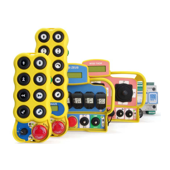
RADIO REMOTE CONTROL
M550
User's Manual
No part of this manual may be reproduced in any way without written authorization from IMET. This manual is subject to change
with no further notice. Every possible care has been taken in compiling and verifying the contents of this manual; however, IMET
declines any responsibility deriving from using the manual or from any errors or omissions in the information contained herein.
Furthermore, IMET cannot be held responsible for damages or problems deriving from using non-original accessories or spare
.
parts. The same applies to any person or company involved in the realization of this manual
M550 ALL1-EN.doc 3nd edition- 04 July 2012
IMET S.r.l. via Fornace no. 8, 33077 Sacile (PN) Italy
Tel +39.0434.7878 Fax +39.0434. 737848
IMET - M550 ALL1-EN
1/53
Advertisement
Table of Contents

Subscribe to Our Youtube Channel
Related Manuals for IMET M550


Summary of Contents for IMET M550
- Page 1 User’s Manual No part of this manual may be reproduced in any way without written authorization from IMET. This manual is subject to change with no further notice. Every possible care has been taken in compiling and verifying the contents of this manual; however, IMET declines any responsibility deriving from using the manual or from any errors or omissions in the information contained herein.
-
Page 2: Table Of Contents
......................30 RANSMITTING UNIT POWER SUPPLY 6.7.1. B .......................... 30 ATTERY STATE OF CHARGE 6.7.2. C ...................... 30 HANGING AND CHARGING THE BATTERY 6.8................31 SWITCH PROGRAMMABLE OUTPUT CONFIGURATIONS RADIO REMOTE CONTROL OPTIONS ....................32 2/53 IMET - M550 ALL1-EN... - Page 3 BATTERY CHARGER FOR TRANSMITTERS RADIO REMOTE CONTROL SPARE PARTS LIST ................51 DISPOSAL ..............................52 ANNEXES ................................52 NNEX NNEX NNEX K-DC ..........................52 NNEX RECEIVERS ..............................52 THER ANNEXES DECLARATION OF CONFORMITY 0470 ..................53 IMET - M550 ALL1-EN 3/53...
-
Page 4: Introduction
INTRODUCTION The M550 family is the result of IMET’s many years’ experience in the production of radio remote controls. IMET radio remote controls are advanced instruments designed and built using state-of-the- art technology. IMET M550 radio remote controls are available in a large number of versions for any application. They are easy to install and they become an integral part of any machine that can be operated by remote control. -
Page 5: Identification Data
55V AC power supply External antenna 110V AC power supply L and K 230V AC power supply Internal antenna Power supply selectable from A to E L-AC only 18-28V AC power supply 12-28V DC/AC power supply Whip antenna IMET - M550 ALL1-EN 5/53... -
Page 6: Documentation
All IMET radio remote controls are accompanied by the following documents: • User’s Manual (the annexes are an integral part of the manual) • Warranty Certificate If any documents are missing, please contact IMET and provide the unit’s serial number. 6/53 IMET - M550 ALL1-EN... -
Page 7: Conventions Used In This Manual
Follow the local laws on safety and workplace accident prevention. All the regulations on using radio remote controls for industrial machinery MUST BE OBSERVED AT ALL TIMES. IMET accepts no responsibility for the unlawful use of the radio remote control. 3.1. Risk analysis It is necessary to evaluate the risks, in order to establish the safety and health safeguard requisites concerning the machine with radio remote control use. -
Page 8: Preventive Maintenance
A and B, of the E-STOP circuit must be opened • Any broken parts must be replaced with original spare parts, in order to keep the characteristics of the radio remote control unchanged. See list of parts that can be replaced in Chapter 11 8/53 IMET - M550 ALL1-EN... -
Page 9: Installing The Radio Remote Control
Data Error ch. A Passive Emergency ch. A RF Busy Power Supply Working RX Unit Mod. M550S HAC Serial no. Supply 24/48/55/110/230V 50/60Hz Power Imax=0.9A 20VA Class Protection IP65 Radio Model M550S - UHF ISM Band LBL550R1 IMET - M550 ALL1-EN 9/53... - Page 10 TRX Unit Mod. M550D MAC Serial no. Supply AC 13 - 24V 50/60Hz Supply DC 13 - 24V Power 1,2A 20VA Radio Model M550D - UHF ISM Band 0470 LB305 LB534 T 1.25A L250V 13 - 24V LB422 10/53 IMET - M550 ALL1-EN...
-
Page 11: Connecting The Receiver
Use a tuned antenna only, and connect it to the receiver using an RG58 coaxial cable (impedance 50Ω). For M550S M8 and M550D M8 type transmitters only use the antennas supplied by IMET, other types of antenna must be approved in conformity to the ETSI EN 300 200-2 standard... -
Page 12: Stop (E-Stop)
PLe according to the ISO13849-1 standard. In order to keep this safety category, the relays must be connected in series (pre-cable standard configuration by IMET) or in parallel ONLY to manage interruption of the main power supply line (See Example 2). -
Page 13: Basic Functions
D, E, an analog output card and, in case of dual transmission, a data feedback card Note: On each project the controls are based on a unique configuration that may be changed only by IMET. IMET - M550 ALL1-EN 13/53... -
Page 14: Hreceiver With Analog Output Card And Data Feedback Card
Version for H-AC T-STOP S-STOP E-STOP E-STOP HORN START LAMP receiver M550RST REV00 IMET RADIO REMOTE CONTROL Version for H- T-STOP S-STOP E-STOP E-STOP HORN START LAMP DC receiver M550RSA REV02 IMET RADIO REMOTE CONTROL 14/53 IMET - M550 ALL1-EN... -
Page 15: Power Supply Connections Of H-Dc And H-Ac Receivers
5.4.2. Power supply connections of H-DC and H-AC receivers 1.25AT 230V 1.25AT 110V 24-55VAC 1.25AT 110-230VAC 0.63AT IMET - M550 ALL1-EN 15/53... -
Page 16: Analog Command Card
* IN AD1, ... ,8 COLLEGATO SOLO PER PWM USED ONLY FOR PWM OUTPUT Control modules M550C2: 0-20mA/4-20mA current-operated control M550C1: PWM current-operated control M550V: voltage-operated control M550C1 (PWM) M550C2 M550V SERIES RANGE SEL. Vout MAX REG. GAIN REG. Vout MIN REG. 16/53 IMET - M550 ALL1-EN... -
Page 17: Logic Board
12 bit A/D converter inputs Auxiliary power supply output (Imax = 5mA) Ground connection inputs CURRENT Current amplification regulator GAIN AD0-AD3 for AD0-AD3 input signal CURRENT GAIN AD0 CURRENT GAIN AD1 CURRENT GAIN AD2 CURRENT GAIN AD3 IMET - M550 ALL1-EN 17/53... -
Page 18: Relay Control Cards
IMET RADIO REMOTE CONTROL M550RMA REV01 5.4.7. Potentiometer card Used for controlling tower cranes. The potentiometer card lets you set the operating speeds independently. Regolazione Regolazione Regolazione Regolazione IV velocita' II velocita' III velocita' I velocita' 18/53 IMET - M550 ALL1-EN... -
Page 19: Connection Diagrams For Land Kreceivers
E- STOP T5A L250V E-STOP contact protection fuse NO/NC relay output START SERIAL DATA IN for RS232 serial CONNECTION Input enabling RS232 (down active) VIN=ENABLE CABLE +10,7 10.7V DC Imax=250mA auxiliary voltage output Ground connection input IMET - M550 ALL1-EN 19/53... -
Page 20: L-Dc Version
T-STOP S-STOP Safety-Stop relay connection T5A L250V S-STOP contact protection fuse SERIAL CONNECTION DATA IN for RS232 serial CABLE Input enabling RS232 (down active) VIN=ENABL +10,7 10.7V DC Imax=250mA auxiliary voltage output Ground connection input 20/53 IMET - M550 ALL1-EN... -
Page 21: Kversion
T5A L250V S-STOP contact protection fuse CAN-H line input CAN-H CAN-L line input CAN-L SERIAL CONNECTION DATA IN for RS232 serial CABLE VIN=ENABLE Input enabling RS232 (down active) VOUT 10.7 10.7V DC Imax=250mA auxiliary voltage output Ground connection input IMET - M550 ALL1-EN 21/53... -
Page 22: Relay Control Cards For Land Kreceivers
C4 / C3 / C3 / C4 / the respective jumpers. C4 = C3 = Version with 12A relays for L-DC and K-DC Version with 16A relays for L-DC and K-DC 22/53 IMET - M550 ALL1-EN... -
Page 23: Other Control Cards For L-Dc And K-Dc Receivers
* IN AD5 M550C1: PWM current-operated control OUT AD4 OUT AD5 M550V: voltage-operated control ANALOG CARD ANALOG CARD CH AD4 CH AD5 * IN AD1, ... ,8 COLLEGATO SOLO PER PWM IMET - M550 ALL1-EN 23/53 USED ONLY FOR PWM OUTPUT... -
Page 24: Serial Data Transmission
After using the serial cable with the radio remote control, disconnect the cable and switch off the transmitter and the receiver to restore radio operation. 24/53 IMET - M550 ALL1-EN... -
Page 25: Connection Diagrams For M-Ac Receivers
Common line for input and output signals POWER IN Input for main power supply POWER SUPPLY T1.25A L250V power supply fuse FUSE ANALOG OUTPUT 5-8 Analog data outputs OUT-VREF 10.7V DC Imax=250mA auxiliary voltage output IMET - M550 ALL1-EN 25/53... -
Page 26: Common Connections On M-Ac Transceivers
ANALOG OUTPUT 5-8 Analog data outputs Input for main power supply POWER IN POWER SUPPLY FUSE 1.25A L250V power supply fuse E-STOP FUSE 5A L250V E-STOP contact protection fuse 5A L250V S-STOP contact protection fuse S-STOP FUSE 26/53 IMET - M550 ALL1-EN... -
Page 27: M-Ac Transceivers: Data Acquisition Connections
DATA ERROR digital outputs and parallel port power supply Parallel port control output DATA ERROR, ACKNOWLEDG Parallel port control output STANDARD PARALLEL PORT Parallel port control input STROBE D0…D7 Parallel port inputs Parallel port common input COMMON D0-D7 IMET - M550 ALL1-EN 27/53... -
Page 28: Using The Radio Remote Control
Standard EN 954-1. Upon explicit request by customers (and under their own responsibility), the auto power-off function can be excluded. In this case the STOP circuit is downgraded to category 3 or PLd. 28/53 IMET - M550 ALL1-EN... -
Page 29: Meaning Of Leds
Data Error ch. A EMERGENCY CH. A Passive Emergency ch. A DATA ERROR CH. A RF Busy EMERGENCY CH. B Power Supply DATA ERROR CH. B Working WORKING M receivers L, K, and H receivers IMET - M550 ALL1-EN 29/53... -
Page 30: Transmitting Unit Power Supply
In this case, use a connector that can be disconnected at any time. If you are using a CB6000-DC battery charger (see Chap. 9.11), protect the connection with a fuse Warning: Explosion hazard if non-compatible batteries are used! Use IMET batteries only. See Chap. 11 for information on the disposal of exhausted batteries. -
Page 31: Dip-Switch Programmable Output Configurations
A4/B4 Distinct second speeds Table 5 1 2 3 4 A6/B6 A5/B5 Start and Horn configurable Table 6 1 2 3 4 A8/B8 A7/B7 More functions customizable on Table … request 1 2 3 4 IMET - M550 ALL1-EN 31/53... -
Page 32: Radio Remote Control Options
The combinations are personalised depending on the clients needs and are programmed by IMET during the radio remote control manufacture. Each transmitter can handle up to 16 different receiver combinations with which it can operate at the same time. -
Page 33: Radio Remote Control Start-Up
The number of dedicated outputs are: • From 1 to 4 for L and M receivers. IMET - M550 ALL1-EN 33/53... -
Page 34: Anomalies
Turning only the transmitting unit off and on will not erase the corrections carried out with the DSC. During the programming or test phase, for minimum and maximum limits of analogue outputs, the DSC function is not active. The DSC function is excluded by the activation of the "Snail-S" mode. 34/53 IMET - M550 ALL1-EN... -
Page 35: Iready Option
SUPPLY activates the relay connected in series with the relay of the radio receiver START START DATA Power 12-24 Vac / 12-28 Vdc Imax 40 m A LED IR LB608 IMET - M550 ALL1-EN 35/53... -
Page 36: Operation
When the white LED (START) of the infrared receiver switches on, it indicates that the START command of the radio remote control has been activated. From this moment on, it is possible to carry out the commands. MAX RANGE Range of action of the infrared receiver 36/53 IMET - M550 ALL1-EN... -
Page 37: Technical Characteristics
Maximum retention time of the relay from 3 seconds when the command is received from the transmitter • IP degree • Dimensions of the receiver mm 126x87x62 ( L.P.H.) • Weight without bracket 0.2 Kg IMET - M550 ALL1-EN 37/53... -
Page 38: Changing The Operating Frequency
If the selected channel is disturbed by interferences, change the frequency again. Interference-free channels are indicated by the “RF Busy” LED on the receiver. The LED is off when the receiver is powered and on when the transmitter is on. 38/53 IMET - M550 ALL1-EN... -
Page 39: Available Frequencies
Latvia Hungary Liechtenstein IMET radio remote controls comply with the specifications of ERC Recommendation 70-03 Annex1 Band E2. The national authorities for telecommunications may impose further restrictions or require use permits in the single countries. We recommend that you become acquainted with the local laws before using the radio remote control. -
Page 40: Troubleshooting
The “Charge” LED turns off after 5-20 minutes Check input voltage stability • Battery charge does not last as long as expected Charge the battery when its is completely exhausted • Check the battery charger's power supply 40/53 IMET - M550 ALL1-EN... -
Page 41: Alfunctions In The Transmitter Stop Circuit
• Description and history of problem, status of receiver and TRX Unit Mod. M550D MAC transmitter LEDs during malfunction Serial no. Keep this manual and the warranty certificate (filled out in every part) in a safe place. IMET - M550 ALL1-EN 41/53... -
Page 42: Technical Specifications
THOR, ZEUS, S1, S2, G4, M8 transmitters with L and K receivers • Max. number of ON/OFF commands • Number of service commands 1 ÷ 3 (Start; Horn and T-Stop optional) • Max. number of analog commands 42/53 IMET - M550 ALL1-EN... -
Page 43: Wave Transmitter
• Visualization speed of characters on display* 100 char/s • Max. number of ON/OFF outputs (NO relay)* • Relay max. capacity* 6A 130V - AC1 / 6A 28V -DC1 • Input ports 21 digital, 8 analog * Transceiver version IMET - M550 ALL1-EN 43/53... -
Page 44: Hreceivers
• Input port* Serial/Parallel • Max. number of digital inputs* • Max. number of analogue inputs • Parallel port data exchange speed* 50000 char/s • Asynchronous serial port data exchange speed* 4800/9600 bit/s • * Transceiver version 44/53 IMET - M550 ALL1-EN... -
Page 45: Lreceiver
-10V DC ÷ 0V DC. ÷ 10V DC • Input ports* Serial/Parallel • Max. number of digital inputs* • Max. number of analog inputs* • Asynchronous serial port data exchange speed* 4800/9600 bit/sec • * Transceiver version IMET - M550 ALL1-EN 45/53... -
Page 46: Kreceiver
-10V DC ÷ 0V DC. ÷ 10V DC • Input ports* CAN/Serial/Parallel • Max. number of digital inputs* • Max. number of analog inputs* • CAN bus interface data exchange speed* <= 500 kbit/s * Transceiver version 46/53 IMET - M550 ALL1-EN... -
Page 47: M-Ac Receivers
Data acquisition input ports* RS232/RS485/Parallel Max. number of digital inputs* Max. number of analog inputs* Parallel port data exchange speed* 50000 char/s Asynchronous serial port data exchange speed* 4800/9600 bit/s * Transceiver version IMET - M550 ALL1-EN 47/53... - Page 48 Receiver weight ≅3.500 kg H series ≅1.700 kg L and K series ≅0.910 kg M series necessary strength of fastening tools ≥ 100N H series ≥ 50N L and K series ≥ 50N M series 48/53 IMET - M550 ALL1-EN...
-
Page 49: Cb5000-Ac, Cb5000-Dc Battery Chargers For Wave Transmitters
Weight including 230V AC transformer (optional) 490g 10.10. CB3600-AC, CB3600-DC battery charger for THOR and ZEUS transmitters • Power supply voltage 12÷32V DC (230V AC optional) • Power demand 35mA AC/250mA DC (during charge) • ≅ 650mA Charging current IMET - M550 ALL1-EN 49/53... -
Page 50: Cb6000-Ac, Cb6000-Dc Battery Charger For S1, S2 And G4 Transmitters
Operating temperature during charge • Storage temperature (charger off and without battery) -20°C ÷ +70°C (-4°F ÷ +158 °F) • Dimensions 137x94x260 mm (L.W.H.) • Weight 250g • Weight including 230V AC transformer (optional) 620g 50/53 IMET - M550 ALL1-EN... -
Page 51: Radio Remote Control Spare Parts List
F13 fuse 5x20 T 1.25A L250V FS002 For L-AC only M-AC receivers Description Item code F1 fuse 5x20 T 1.25A L250V FS002 F2 fuse 5x20 T 5A L250V FS005 F3 fuse 5x20 T 5A L250V FS005 IMET - M550 ALL1-EN 51/53... -
Page 52: Disposal
Arrangement and electric symbols of the actuators in the transmitting unit. Annex B Table of controls. Annex C Wiring diagram of the outputs in the receiving unit. Annex D for K-DC receivers Details of CAN bus interface. Other annexes Special functions 52/53 IMET - M550 ALL1-EN... -
Page 53: Declaration Of Conformity 0470
0470 13. DECLARATION OF CONFORMITY The IMET Radio Remote Control, model M550 Date of installation Year of manufacture Serial no. TRANSMITTING M550 UNIT ID RECEIVER M550 UNIT is suitable for installation on machines or other equipment conforming with European Directive 2006/42/EC (“Machinery Directive”)
Need help?
Do you have a question about the M550 and is the answer not in the manual?
Questions and answers