Table of Contents
Advertisement
Advertisement
Table of Contents

Summary of Contents for joule DeltaSol BS/2 HE
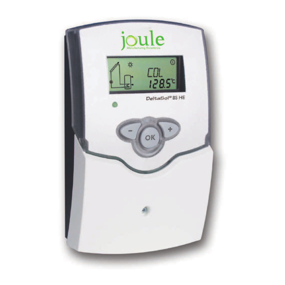
- Page 1 ® BS/2 HE DeltaSol Solar controller Manual for the specialised craftsman Installation Operation Functions and options Troubleshooting Thank you for buying this product. Manual Please read this manual carefully to get the best performance from this unit. Please keep this manual carefully.
- Page 2 Safety advice Target group Please pay attention to the following safety advice in order to avoid danger and These instructions are exclusively addressed to authorised skilled personnel. damage to people and property. Instructions named by the system owner. Attention must be paid to the valid local standards, regulations and directives! Description of symbols Information about the product WARNING! Warnings are indicated with a warning triangle!
-
Page 3: Table Of Contents
® BS/2 HE solar controller DeltaSol sensors and pumps enable an immediate allocation of temperatures, temperature The controller for standard solar thermal systems. differences and active actuators. Thus, adjusting and monitoring the solar system is The DeltaSol ® BS/2 HE controller provides a clear operating concept and is quick and easy. -
Page 4: Overview
Overview Technical data • Inputs: 3 Pt1000 temperature sensors • System-Monitoring-Display Outputs: 1 semiconductor relay, 1 PWM output • Up to 3 Pt1000 temperature sensors Switching capacity: 1 (1) A 240 V~ (semiconductor relay) • Heat quantity measurement Total switching capacity: 1 A 240 V~ Power supply: 220 …... -
Page 5: Installation
Installation 2.1 Mounting display WARNING! Electric shock! Upon opening the housing, live parts are exposed! Always disconnect the device from power supply before opening the housing! Note: button Make sure the controller as well as the system are not exposed to cover The unit must only be located in dry interior rooms. -
Page 6: Electrical Connection
2.2 Electrical connection Fuse WARNING! Electric shock! Upon opening the housing, live parts are exposed! Always disconnect the device from power supply before 220 ... 240 V~ DeltaSol BS HE 50-60 Hz opening the housing! IP 20 ATTENTION! ESD damage! R1 1 (1) A 220 ... -
Page 7: System: Standard Solar System With 1 Store
2.4 System: Standard solar system with 1 store Sensor S3 can optionally be connected for measurement purposes. The controller calculates the temperature difference between collector sensor S1 and store sensor S2. If the difference is larger than or identical to the adjusted If heat quantity measurement (OHQM) is activated, S3 is to be used as the return switch-on temperature difference (DT O), the solar pump will be activated by the sensor. - Page 8 Display channels Adjustment channels Connection Channel Description Factory setting Page Channel Description Page terminal DT O Switch-on temperature difference 6.0 K Temperature collector DT F Switch-off temperature difference 4.0 K Temperature store DT S Set temperature difference 10.0 K Temperature sensor 3 Rise Temperature return sensor S MX...
-
Page 9: Operation And Function
Operation and function System-Monitoring-Display 3.1 Buttons System-Monitoring-Display Operating control The System-Monitoring-Display consists of 3 blocks: channel display, tool bar and 1 forwards (+) system screen. 2 backwards (-) Channel display (selection / The channel display consists of 2 lines. The upper display line is an alphanumeric 16-segment display. -
Page 10: System Screen
4.1 System screen 4.2 Other indications The system selected is indicated in the System-Monitoring-Display. It consists of System screen several system component symbols which are – depending on the current status of • • lected • Operating control LED Green: Everything OK Manual mode Permanently... -
Page 11: Channel Overview
Channel overview 5.1 Display channels Note: Indication of return temperature The display and adjustment channels as well as the adjustment ranges de- pend on the functions and options as well as on the system components connected to the controller. Display of collector temperatures Return temperature Display range: -40 …... -
Page 12: Adjustment Channels
5.2 Adjustment channels The accumulated heat quantity can be set back to zero. As soon as one of the dis- T control play channels of the heat quantity is selected, the symbol is displayed. In order to access the reset mode of the counter, press button 3 for approx. 2 s. In order to interrupt the reset process, do not press any button for about 5 s. -
Page 13: Dt S X Set Temperature Difference 10.0 K
Speed control Maximum store temperature DT S S MX Set temperature difference Maximum store temperature Adjustment range: 1.5 … 30.0 K Adjustment range: 4 … 95 °C Factory setting: 10.0 K Factory setting: 60 °C If the store temperature reaches the adjusted maximum temperature, the store will Note: no longer be loaded in order to avoid damage caused by overheating. - Page 14 Collector cooling If the collector minimum limitation option is activated, the pump (R1) will only be switched on if the adjustable collector minimum temperature is exceeded. The minimum temperature prevents the pump from being switched on too often at low collector temperatures.
-
Page 15: Ohqm
Recooling function Heat quantity measurement OREC OHQM FMAX Recooling option Heat quantity measurement Flow rate in l/min Adjustment range: OFF / ON Adjustment range: OFF / ON Adjustment range: 0.5 … 100.0 Factory setting: OFF Factory setting: OFF Factory setting: 6.0 When the recooling function is activated, the controller aims to cool down the store during the night in order to prepare it for solar loading on the following day. -
Page 16: Nmx
Maximum speed Operating mode Maximum speed Operating mode Adjustment range: 22 … 100 % Adjustment range: OFF, AUtO, ON Factory setting: 100 % Factory setting: AUtO A relative maximum pump speed can be allocated to the PWM output via the For control and service work, the operating mode of the relay can be manually ad- adjustment channel nMX. -
Page 17: Troubleshooting
Troubleshooting If a malfunction occurs, the display symbols will indicate an error code: The symbol is indicated on the display and the symbol Sensor fault. An error code instead of a temperature is shown on the sensor display channel. 888.8 - 88.8 Cable is broken. - Page 18 Pump starts up very late. and return have the same temperature; perhaps also bubbling in the lines. Air or gas bubbles in the system? Vent the system; increase the Switch-on temperature difference Ton too large? system pressure to a static primary pressure of at least plus 0.5 bar Change Ton and Toff corre- [7.25 psi];...
- Page 19 Stores cool down at night. Check the non-return valve in warm Further pumps which are connect- Collector circuit pump runs during water circulation - o.k. ed to the solar store must also be the night? checked. Check the controller. Clean or replace it. Collector temperature at night is The gravitation circulation in the higher than the outdoor temper-...
-
Page 20: Accessories
Accessories Sensors AM1 Alarm Module Overvoltage protection KM1 Communication device module SD3 Smart Display / GA3 DL2 Datalogger Large Display VBus ® / USB & VBus ® / LAN interface adapters... -
Page 21: Sensors And Measuring Instruments
7.1 Sensors and measuring instruments Sensors KM1 Communication module The KM1 Communication module is the network connection for solar and heating sensors, outdoor temperature sensors, indoor temperature sensors, cylindrical clip- systems, especially suited for technicians managing large systems, heating installers on sensors, also as complete sensors with immersion sleeve. -
Page 22: Index
Index Accessories.......................... 20 Operating mode ......................... 16 Antifreeze function ......................14 Recooling function ......................15 Collector cooling ....................... 14 Collector emergency shutdown ..................13 Sensors ..........................11 Speed control ........................13 T control ........................... 12 System screen ........................10 Data communication / Bus ....................6 Displays .......................... - Page 24 Distributed by: Joule Manufacturing Excellence Kylemore Park West Ballyfermot Dublin 10 t. +353 1 6286489 f. +353 1 6286528 © All contents of this document are protected by copyright...
Need help?
Do you have a question about the DeltaSol BS/2 HE and is the answer not in the manual?
Questions and answers
The pump for the solar collectors won't switch on and the controller is showing the flashing triangle symbol. The temperature on the collectors is high 125° and the store water is 19°. Thanks.