Advertisement
Operating
Instructions
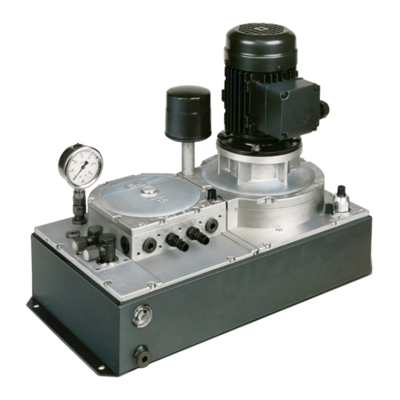
Pneumohydraulic controller
HP 036./HP 037.
2
3
5
7
9
10
14
15
16
BEA--206006-EN-04
en
Advertisement
Table of Contents

Summary of Contents for Et HP 036.
-
Page 1: Table Of Contents
Operating Instructions Pneumohydraulic controller HP 036./HP 037. 1. Safey 2. Function 3. Variants 4. Mounting 5. Installation 6. Commissioning 7. Maintenance 8. Spare Parts 9. Technical Data BEA--206006-EN-04... -
Page 2: Safey
Pneumohydraulic controller HP 036./HP 037. 1. Safey 1.1 Approved applications The E+L controller HP 03.. must only be used to operate a hydraulic positioning device. Only use the controller - if it is in perfect condition technically - in accordance with its intended usage - with an awareness of safety and risk factors and in compliance with the operating instructions. -
Page 3: Function
Pneumohydraulic controller HP 036./HP 037. 2. Function 2.1 Purpose The HP 03.. controller is used to position actuators in web guiding systems or in unwinding/rewinding stations. The controller is desig- ned for systems guiding by the web edge with a pneumatic sensor FL2.. - Page 4 Pneumohydraulic controller HP 036./HP 037. Fuses Motor protec- tion switch Contactor Connection terminals Switch panel SE 12521 The HP 03.. controller is available in three different electrical versi- ons. - Switch panel SE 12521 with motor protection switch, three-phase a.c. motor contactor and connection terminals for the valve wiring. - Terminal box SZ 0921 with connecting terminals only for the three- phase a.c.
-
Page 5: Variants
Pneumohydraulic controller HP 036./HP 037. 3. Variants 3.1 Basic model, system 1 On the basic model HP 03.. without valve assembly, guiding by the web edge only (automatic) is possible. = pneumatic sensor HZ = positioning device - HZ :S 2 - FL :S 1 :S 1.1... - Page 6 Pneumohydraulic controller HP 036./HP 037. 3.3 Valve assembly 03, Valve assembly 03 permits guiding by the web edge (automatic) or system 2a servo center. Reversing is effected via solenoid valves. = pneumatic sensor = positioning device = servo center actuator - Y 3 Y 2/Y 3 = solenoid valves - HZ...
-
Page 7: Mounting
Pneumohydraulic controller HP 036./HP 037. 3.5 Valve assembly 06, Web guiding is by the web edge (automatic) or servo center. The system 2ab positioning cylinder can be set via pushbuttons. A P/T connection is possible with this valve assembly (please quote it however when or- dering controller HP 03..). - Page 8 Pneumohydraulic controller HP 036./HP 037. 4.2 Switch panel The switch panel or terminal box can be mounted in three positions (see fig. below). Standard Mounting options 4.3 Pneumatic sensor When the web passes through the air sensor on the horizontal, sen- sor connection S 1 should be located underneath the web (see fig.
-
Page 9: Installation
Pneumohydraulic controller HP 036./HP 037. 4.3 Positioning cylinder The positioning cylinder should be connected as follows. When the FL 2.. pneumatic sensor is uncovered, the fluid flow is from to A to B. The positioning cylinder must be connected so that it moves towards the pneumatic sensor (see fig. -
Page 10: Commissioning
Pneumohydraulic controller HP 036./HP 037. 6. Commissioning Once the fluid filler conver has been removed, the hydraulic fluid should be poured in using a funnel and filter paper. the fluid leven must not rise above the halfway mark on the fluid inspection window. The direction of rotation can be checked by briefly applying voltage to the three phase a.c. - Page 11 Pneumohydraulic controller HP 036./HP 037. Covered sensor jets Uncovered sensor jets HP 03 HP 03 Pneumatic Pneumatic sensor sensor Sensor jets Sensor jets Positioning Positioning cylinder cylinder Positioning cylinder di- Positioning cylinder di- rection of stroke rection of stroke The hydraulic system is vented by advancing the positioning cy-linder to its end positions several times.
- Page 12 Pneumohydraulic controller HP 036./HP 037. 6.3 Adjusting the pneumatic The basic setting when the pneumatic sensor is uncovered is system 12 mbar (= 120 mm water column), measured at S 2. For sensitive webs, the S 2 signal pressure can be reduced to approx. 9 mbar (90 mm water column).
- Page 13 Pneumohydraulic controller HP 036./HP 037. 6.5 Setting the positioning The controller is factory preset to maximum speed. By turning the speed fluid restrictor (see fig. below) by approx. 5 turns to the right, the po- sitioning speed is reduced by approx. 50 %. If the system should dis- play a tendency to hunt, we recommend you reduce the positioning speed.
-
Page 14: Maintenance
Pneumohydraulic controller HP 036./HP 037. 7. Maintenance 7.1 Controller HP 03.. The air intake filter should be renewed at regular intervals depending on the amount of dust in the ambient air. Check regulary that the hydraulic fluid and pipe connections are tight. The level and purity of the hydraulic fluid must be checked regular- ly. -
Page 15: Spare Parts
Pneumohydraulic controller HP 036./HP 037. The fluid intake filter is located on the gear pump. Once the nut has been removed (see fig. on right), the filter insert can be taken out. If heavily soiled, the filters should be replaced. Depending on the de- gree of soiling, the fluid tank should be clean ed. -
Page 16: Technical Data
Erhardt + Leimer GmbH Postfach 10 15 40 D-86136 Augsburg Phone (0821) 24 35-0 Telefax (0821) 24 35-6 66 Internet http://www.erhardt-leimer.com E-mail info@erhardt-leimer.com 8.2 Electrical components The electrical spare parts are dependent on the on-site control volta- (only in conjunction with a switch panel) Miniature fuse (5x30) 10 AM (24 V) 070646 Miniature fuse (5x30) 4 AM (120 V)
Need help?
Do you have a question about the HP 036. and is the answer not in the manual?
Questions and answers