Table of Contents
Advertisement
Advertisement
Table of Contents

Related Manuals for Option Wireless Technology CG0114

Summary of Contents for Option Wireless Technology CG0114
- Page 1 User guide CloudGate LTE WW (CG0114)
-
Page 2: Table Of Contents
Table Of Content 1. CloudGate LTE WW (CG0114) ....................3 1.1. Main Board ......................... 5 1.2. Front & Back View ....................... 7 1.3. LED Indicators ........................10 1.4. Ethernet Interface ......................13 1.5. RF & Antennas Specs ......................15 1.5.1. Antenna Specs ...................... -
Page 3: Cloudgate Lte Ww (Cg0114)
CloudGate LTE WW Model: CG0114 Last updated on 29/11/2016 The CloudGate LTE WW is a 4G multiband M2M gateway providing internet connectivity at LTE Cat 3 data rates. The base unit is designed around a main board and a WWAN module. It's main features... - Page 4 Feature Description MicroSD card reader For additional storage (FAT32). Located underneath the Cellular modem PCB inside the CloudGate LTE WW. Power input DC input voltage: 9-33 V DC Connector type: Micro-Fit 3.0™, Dual row, 4 circuits Expansion Card Slots Two expansion card slots (one at the front and one at the back side of the device) Expansion boards for I/O functions,...
-
Page 5: Main Board
1.2.1. Main Board The CloudGate LTE WW is designed around a main board and a 4G WWAN module. The processor on the main board controls all the interfaces. The WWAN module provides the wireless connectivity to to the internet. The CloudGate also has two expansion board connectors to allow insertion of dedicated expansion cards. - Page 6 Serial interface Secondary Expansion Card Slot The secondary expansion board has the following interfaces: Power supply: V_PWR, 3V4, 3V3 24 MHz clock signal Master reset signal High speed USB interface SDIO interface GPIO signals WWAN module The WWAN module in the CloudGate LTE WW is the LN930 module. It supports LTE Cat 3.
-
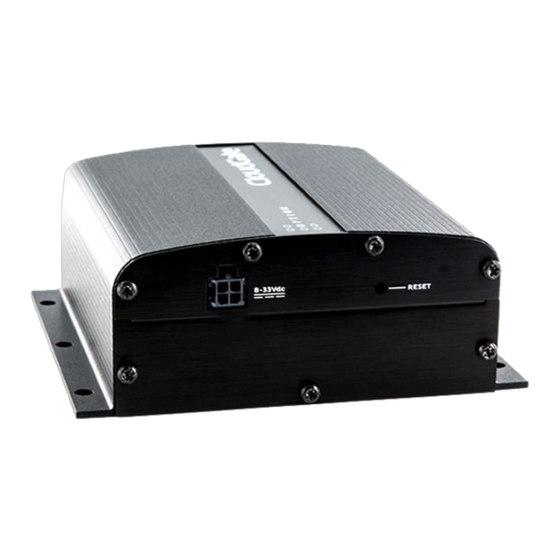
Page 7: Front & Back View
Front and Back View The CloudGate Base Unit is assembled in the top half of the device. The bottom half is available to insert expansion cards. The front and back side of the CloudGate housing are closed by means of metal panels that are secured with Torx T6 screws. -
Page 8: Back View
A detailed description of the LEDs is given in the section about the LED Indicators. Bottom Front Panel The bottom front panel covers the front expansion slot and has to be removed when installing a Primary Expansion Card. Option provides a custom panel for the following primary expansion cards: Low Cost Serial Card Industrial Serial Card Ethernet Switch... - Page 9 The functionality of the button is explained in the section about the Reset button Behind the top back panel there is a socket for insertion of a SIM card. Please also refer to the section about the SIM Card Interface for more details. Bottom Back Panel The bottom back panel covers the back expansion slot and has to be removed when installing a Secondary Expansion Card.
-
Page 10: Led Indicators
1.2.3. LED Indicators Description WLAN State Indicates the connection status of the WLAN interface Off: not installed Orange: WLAN board = OK, client not connected and AP not enabled Orange blinking: AP disabled and Client connected / data traffic Red: board error/ (Any that causes AP or Client not to work) Green:... - Page 11 Description Green: on, has fix Green flashing: GPS/Aux signal strength Indicates the signal strength of the GPS Off: no signal Orange: moderate GPS signal Red: bad GPS signal Green: good GPS signal Green flashing: n/a System State Indicates successful power on and device readiness Off: no power Orange:...
- Page 12 moving fast from left to right and back. The colors of the LEDs indicate the next: Orange: A new firmware is being downloaded Green: The download was successful. (This will be followed by a reset of the CloudGate) Red: The download was not successful. During the bootup process When the CloudGate is booting up, the System State LED behaviour is different compared to normal behaviour.
-
Page 13: Ethernet Interface
1.2.4. Ethernet Interface This section describes the Ethernet interface on the CloudGate main board. Ethernet Interface RJ-45 receptacle tab on top 10/100 Mbps 100BASE-TX Auto-MDIX Pinout Yellow LED: Active when operating speed is 100 Mbps Inactive when operating speed is 10 Mbps or when not connected Green LED: Active when valid links are detected Blinks when activity is detected... - Page 14 Pin # Function Not used RX/TX- Not used Not used IMPORTANT: The auto-MDIX feature is always activated on the CloudGate. This feature automatically detects the required cable connection type (straight or crossed), and configures the connection appropriately, removing the need for crossover cables. In order for auto-MDIX to work correctly, auto-negotiation (auto speed and auto duplex) must be enabled on both sides of the link.
-
Page 15: Rf & Antennas Specs
RF and antenna specifications of the CloudGate LTE WW Warning for antenna assembly The antenna has to be assembled in such a way that only the nut is rotating onto the SMA connector. The antenna body itself may not be rotated. In this way the inner conductor of the antenna is sliding into the SMA connector without rotation. - Page 16 Main WWAN Antenna The main antenna is labelled WWAN Main on the front panel. Learn about antenna recommendations for the CloudGate LTE WW. Connectors The RF connector on the CloudGate is SMA female. The antenna itself or the connector to the antenna should be SMA male. Frequency Range Allows all frequency bands which the integrator wants to use Performance...
-
Page 17: Gps Antenna
Diversity WWAN Antenna The diversity antenna is labelled WWAN Div GPS on the front panel. Learn about antenna recommendations for the CloudGate LTE WW. IMPORTANT: The diversity antenna is by default disabled (from firmware version 1.9.0 onwards). Learn how to enable the diversity antenna. Connectors Uses the same type of connector as the main WWAN antenna Frequency range... - Page 18 < 2.5:1 with 50 ohms reference impedance Polarization RHCP antenna or a vertical polarized antenna Frequency range Frequency range for GPS: 1575.42 MHz ± 1 MHz Efficiency Efficiency: > 50%. Important: a CloudGate LTE WW with active GPS does not support the MIMO LTE antenna.
-
Page 19: Antenna Specs
Antenna recommendations for the CloudGate LTE WW A number of good antennas are available on the market for use with the CloudGate. Below is a list of antennas which can be used as a reference for each functionality. The antenna's below, made by Taoglas, are available via DigiKey. The antenna's below, made by Grand-Tek, are only available via OPTION or a CloudGate reseller. -
Page 20: Related Topics
Diversity and GPS Antenna Option A Taoglas TG.30.8113 Recommended as Diversity and GPS antenna Operating temperature range: -40°C to +85°C Option B Grand-Tek OA-LTE-01-01-GTT Recommended as Diversity antenna Operating temperature range: -10°C to +55°C Not recommended for GPS Important: a CloudGate LTE WW with active GPS does not support the MIMO LTE antenna. -
Page 21: Active Gps
CloudGate LTE WW with active GPS Customers who need active GPS have to order a dedicated variant of the CloudGate. This variant supplies 3.4V to the SMA connector in order to power the LNA in the active GPS antenna. Requirements for the active GPS antenna Support GPS and Glonass Noise Figure <... - Page 22 Warning: a CloudGate LTE WW with active GPS does not support a MIMO LTE antenna...
-
Page 23: Power Requirements
1.6. Power Requirements Base Unit Power Supply The symbol on the label at the bottom side of the CloudGate shows the power requirements: Input voltage must be between 9V - 33V DC Internal electronic fuse limits the input current to 1.2A For the power cable between the external power supply unit and the CloudGate Option recommends to use a power cable that has a wire thickness of 22 AWG! SAFETY WARNING... -
Page 24: Power Connector
Power Connector The power connector is a Micro-Fit connector from Molex (MX-43025-0400) Power Connector Drawing (PDF) Power Connector Datasheet (PDF) Pinout The following drawing shows the pinout of the power connector, seen from the terminal side. Pin # Function Input voltage Ignition sense input Not connected Ignition sense... -
Page 25: Power Consumption
be read as a ‘1’ when the level is higher than 4.1V. Levels in between are undefined/unpredictable. The explanation about the ignition sense feature and how to use it can be found in the Software Developer Kit, under the title "How to use the ignition sense". Power Consumption You can find here a document describing all the different power consumption numbers Preventing Fuse Overload... -
Page 26: Internal Power Circuits
1.2.6.1. Internal Power Circuits The voltage applied by the power adapter to the CloudGate is converted into different voltage rails on the main board. Two different power circuits make five different voltage rails. Dedicated high current power circuit Provides two different voltage rails which both can deliver high current levels: V_PWR: At the power adapter input of the CloudGate there is an overvoltage protection circuit and a current limiter of 1.2A. - Page 27 translators, e.g. output buck between I/O signals converter (3V3, 1V8 from the processor and 1V2). The and circuitery on the maximum output main board or on current capability of the expansion cards each output of the converter is dependent on the loads on the other two outputs.
-
Page 29: Sim Card Interface
SIM Card Requirements The CloudGate has an integrated (U)SIM interface compatible with the ISO7816 IC card standard. The 3GPP standard defines three operational voltages for the supply voltage of the SIM card: 1.8V, 3V and 5V. The CloudGate supports two voltages: 1.8V and 3V. The 5V-only SIM cards are rarely used and are not supported by the CloudGate. -
Page 30: Reset Button
1.2.8. Reset Button On the back side of the unit there is a reset button behind the hole in the top panel (indicated by the "2" in the picture above). This button allows to restart the unit or to reset it to the factory settings: press and hold for less than ten seconds to reset the unit to the last working settings, press and hold for ten seconds or more to reset the unit to factory settings. -
Page 31: Mechanical Drawings
1.2.9. Mechanical Drawings 3D file of the CloudGate. 3D file of the front plate of the expansion cards Below you can find the dimensions of the CloudGate. - Page 32 The 6 mounting holes in the CloudGate housing allow mounting on a wall or on a DIN rail. See the details in the "Mounting" section of the CloudGate Installation Guide. Note 1: The front plate for the expansion cards, both at the front and at the back side of the CloudGate, are identical.
-
Page 33: Requirements
1.2.9.1. IP-65 Requirements Below you can find the parts for the encasing which are needed to fulfill the requirements for IP-65. All these parts can be ordered by TAKACHI: 1x box BCAK 203013G or BCPK 203013S, 1x plate BMP 2030P, 1 x screws (20pcs) MT4-8T, 1x bracket (2x4 pcs) BLF-2G(PC-GF) or CK-26P (metal SS) 3x cable gland MG-12S (3 inputs) -
Page 35: Environmental Specs
Environmental Specifications Operating temperature: -30°C to 70° (*) see Safety Warning below Storage temperature: -40°C to 85°C Humidity operational: 5% - 95% non condensing Operating altitude: up to 2000m Safety Warning When the device is installed in a location where the environmental temperature can rise above 60°C, the temperature of the surface might reach high values and therefore under these conditions the user needs to warned in order to prevent accidental contact. -
Page 36: Shock Resistance
Shock Resistance The next tests have been performed on the CloudGate and passed: • EUT state: operational • Frequency range: 10 … 2000Hz • Overall acceleration: 3.6Grms • Crest Factor: 3 • Orientation: 3 axis, X / Y / Z •... -
Page 37: Railway
Railway applications The CloudGate LTE has successfully been tested according to EN 50155. This standard applies to all electronic equipment installed on rail vehicles and associated with the accumulator battery of the vehicle or a low voltage power supply. Conditions of operation This device is suited for railway applications under the following conditions: altitude class AX (up to 2000m) ambient temperature class T3 (-25°C to +70°C) -
Page 38: Certifications & Approvals
Certification information for CloudGate LTE WW Model: CG0114 This page offers an overview of the country certifications and operator approvals obtained per region. This CloudGate model is approved for use in the countries listed below. For use in other countries, please consult your sales contact. - Page 39 The CloudGate LTE WW can be used in Canada and complies with the applicable Industry Canada regulations. The product completed PTCRB certification and is approved by the following network operators: Bell Mobility Rogers The CloudGate LTE WW can be used in Class I Div 2 Hazardous Locations. Click here for conditions for use.
- Page 40 Le présent appareil est conforme aux CNR d'Industrie Canada applicables aux appareils radio exempts de licence. L'exploitation est autorisée aux deux conditions suivantes: (1) l'appareil ne doit pas produire de brouillage, et (2) l'utilisateur de l'appareil doit accepter tout brouillage radioélectrique subi, même si le brouillage est susceptible d'en compromettre le fonctionnement.
- Page 41 The CloudGate LTE WW can be used in Colombia and complies with the CRC requirements. The certificate can be found here. El Salvador The CloudGate LTE WW can be used in El Salvador and complies with the SIGET requirements. The certificate can be found here. European Economic Area The CloudGate LTE WW complies with the essential requirements of the R&TTE directive (1999/5/EC) issued by the Commission of the European Union and carries the CE mark.
- Page 42 regulation UN ECE-R10 revision 4 and EU Automotive EMC directive 2004/104/EC. It carries the E-mark E13. EN 50155 (Railway) This product has successfully been tested for compliance with standard EN 50155 and is suitable for railway applications. For more info on Railway applications, click here Waste from Electrical and Electronic Equipment (WEEE) Attention: Your product is marked with this symbol.
-
Page 43: United States
The certificate can be found here. Switzerland The CloudGate LTE WW carries the CE mark and can be used in Switzerland. Turkey The CloudGate LTE WW carries the CE mark and can be used in Turkey. United States The CloudGate LTE WW can be used in the USA and complies with the applicable FCC rule parts. - Page 44 device, pursuant to part 15 of the FCC Rules. These limits are designed to provide reasonable protection against harmful interference when the equipment is operated in a commercial environment. This equipment generates, uses, and can radiate radio frequency energy and, if not installed and used in accordance with the instruction manual, may cause harmful interference to radio communications.
-
Page 45: Hazardous Locations
Class I Div 2 Hazardous Locations Model: CG0114 Expansion card models CG2101, CG1102, CG1106, CG3102 This page offers information on using your CloudGate product in Class I Div 2 Hazardous Locations in the countries listed below. For use in other countries, please consult your sales contact.
Need help?
Do you have a question about the CG0114 and is the answer not in the manual?
Questions and answers