Table of Contents
Advertisement
Quick Links
Rhein Tech Laboratories
Client: M/A-COM, Inc.
360 Herndon Parkway
Model: P5400 UHF-L Portable Radio
Suite 1400
ID's: OWDTR-0045-E/3636B-0045
Herndon, VA 20170
Standards: Part 90/RSS-119
http://www.rheintech.com
Report #: 2007147
Appendix J:
User Manual
Please refer to the following pages for the operator's manual and the product safety manual.
44 of 64
Advertisement
Table of Contents

Summary of Contents for Tyco P5400 series
- Page 1 Rhein Tech Laboratories Client: M/A-COM, Inc. 360 Herndon Parkway Model: P5400 UHF-L Portable Radio Suite 1400 ID’s: OWDTR-0045-E/3636B-0045 Herndon, VA 20170 Standards: Part 90/RSS-119 http://www.rheintech.com Report #: 2007147 Appendix J: User Manual Please refer to the following pages for the operator’s manual and the product safety manual. 44 of 64...
- Page 2 Operator’s Manual MM-012099-001 Rev. p1, Jul/07 M/A-COM P5400 Series Portable Radio...
- Page 3 M/A-COM Technical Publications would particularly appreciate feedback on any errors found in this document and suggestions on how the document could be improved. Submit your comments and suggestions to: Tyco Electronics Wireless Systems Segment M/A-COM, Inc. Fax your comments to: 1-434-455-6851...
-
Page 4: Table Of Contents
MM-012099-001 TABLE OF CONTENTS Page SAFETY CONVENTIONS........................10 SAFETY TRAINING INFORMATION ....................8 RF EXPOSURE GUIDELINES ....................8 ELECTROMAGNETIC INTERFERENCE/COMPATIBILITY..........12 OPERATING TIPS ..........................13 EFFICIENT RADIO OPERATION ...................13 3.1.1 Antenna Care and Replacement..................13 3.1.2 Electronic Devices ......................13 3.1.3 Aircraft...........................14 3.1.4 Electric Blasting Caps ....................14 3.1.5 Potentially Explosive Atmospheres................14 BATTERIES ............................15... - Page 5 MM-012099-001 TABLE OF CONTENTS Page ALERT TONES..........................39 SYSTEM SELECTION......................39 8.10 GROUP/CHANNEL SELECTION....................40 8.11 MODIFY SCAN LIST .......................40 8.11.1 P5470 Model........................40 8.11.2 P5450 Model........................40 8.12 BACKLIGHT ON/OFF ......................41 8.13 CONTRAST ADJUST .......................41 8.14 DECLARING AN EMERGENCY.....................41 8.15 LOCKING/UNLOCKING KEYPAD ..................41 8.16 HIGH/LOW POWER ADJUSTMENT ..................41 8.16.1 Using the Menu Button....................42 8.16.2 Using the Pre-Programmed Option Button..............42...
- Page 6 MM-012099-001 TABLE OF CONTENTS Page 8.28 PORTABLE DATA........................59 8.28.1 Displays .........................59 8.28.2 DATA OFF Operation....................60 8.28.3 DATA ON Operation ....................60 8.28.4 Exiting Data Cells......................60 8.28.5 Scan Lockout Mode.......................60 8.28.6 Data Lockout Mode .......................61 CONVENTIONAL OPERATION ......................64 CONTROLS ..........................64 9.1.1 Buttons and Knobs......................64 9.1.2 Keypad...........................65 DISPLAY ...........................67...
- Page 7 MM-012099-001 TABLE OF CONTENTS Page 10.8 SYSTEM SELECTION......................87 10.9 GROUP/CHANNEL SELECTION....................88 10.10 MODIFY SCAN LIST .......................88 10.10.1 P5470 Model........................88 10.10.2 P5450 Model........................88 10.11 BACKLIGHT ON/OFF ......................89 10.12 CONTRAST ADJUST .......................89 10.13 DECLARING AN EMERGENCY.....................89 10.14 LOCKING/UNLOCKING KEYPAD ..................89 10.15 HIGH/LOW POWER ADJUSTMENT ..................89 10.15.1 Using the Menu Button....................90 10.15.2 Using the Pre-Programmed Option Button..............90 10.16 MENU ............................90...
- Page 8 MM-012099-001 TABLE OF CONTENTS Page 10.27.1 Displays ........................107 10.27.2 DATA OFF Operation....................108 10.27.3 DATA ON Operation ....................108 10.27.4 Exiting Data Calls......................108 10.27.5 Scan Lockout Mode.....................108 10.27.6 Data Lockout Mode .....................109 10.28 GROUP CALLS IN P25 MODE ....................109 10.28.1 Transmitting a Group Call ...................109 10.28.2 Receiving a Group Call ....................109 10.29 INDIVIDUAL CALLS IN P25 MODE..................109 10.29.1 Transmitting an Individual Call...................109...
- Page 9 MM-012099-001 TABLE OF CONTENTS Page Figure 9-6: Menu Display ..........................73 Figure 9-7: Backlight Menu Item Parameter ....................73 Figure 9-8: Backlight Menu Display......................74 Figure 10-1: P5450 “Scan” Radio Front Panel ....................81 Figure 10-2: P5470 “System” Radio Front Panel ..................82 Figure 10-3: Radio Display..........................
- Page 10 MM-012099-001 SAFETY SECTION...
-
Page 11: Safety Conventions
MM-012099-001 SAFETY CONVENTIONS The following conventions are used throughout this manual to alert the user to general safety precautions that must be observed during all phases of operation, service, and repair of this product. Failure to comply with these precautions or with specific warning elsewhere in this manual violates safety standards of design, manufacture, and intended use of the product. -
Page 12: Safety Training Information
MM-012099-001 SAFETY TRAINING INFORMATION The M/A-COM P5400 portable radio generates RF electromagnetic energy during transmit mode. This radio is designed for and classified as “Occupational Use Only,” meaning it must be used only during the course of employment by individuals aware of the hazards and the ways to minimize such hazards. This radio is NOT intended for use by the “General Population”... -
Page 13: Electromagnetic Interference/Compatibility
MM-012099-001 • As noted in Table 2-1, ALWAYS keep the device and its antenna AT LEAST 1.1 cm (0.43 inches) from the body and at least 2.5 cm (1.0 inch) from the face when transmitting to ensure FCC RF exposure compliance requirements are not exceeded. However, to provide the best sound quality to the recipients of your transmission, M/A-COM recommends you hold the microphone at least 5 cm (2 inches) from mouth, and slightly off to one side. -
Page 14: Operating Tips
MM-012099-001 OPERATING TIPS Antenna location and condition are important when operating a portable radio. Operating the radio in low lying areas or terrain, under power lines or bridges, inside of a vehicle or in a metal framed building can severely reduce the range of the unit. Mountains can also reduce the range of the unit. In areas where transmission or reception is poor, some improvement may be obtained by ensuring that the antenna is vertical. -
Page 15: Aircraft
MM-012099-001 3.1.3 Aircraft • Always turn off a portable radio before boarding any aircraft! • Use it on the ground only with crew permission. • DO NOT use while in-flight!! 3.1.4 Electric Blasting Caps To prevent accidental detonation of electric blasting caps, DO NOT use two-way radios within 1000 feet of blasting operations. -
Page 16: Batteries
MM-012099-001 BATTERIES The P5400 series portable radios use rechargeable, recyclable Nickel Cadmium (NiCd), Nickel Metal Hydride (NiMH), or Lithium Ion (Li Ion) batteries. Please follow the directions below to maximize the useful life of each type of battery. Do not disassemble or modify Lithium Ion battery packs. The Lithium Ion battery packs are equipped with built-in safety and protection features. -
Page 17: Additional Information
MM-012099-001 Always use M/A-COM authorized chargers and conditioners. Use of unauthorized chargers and conditioners may void the warranty. CAUTION 4.1.3 Additional Information For more information regarding the proper care of portable radio batteries or establishing a battery maintenance program, refer to ECR-7367 which may be ordered by calling toll free 1-800-368-3277, then select option 7. -
Page 18: Changing The Battery Pack
MM-012099-001 Do not leave any M/A-COM rechargeable batteries in a charger for more than a few days. CHANGING THE BATTERY PACK 4.4.1 Removing the Battery Pack Make sure the power to the radio is turned OFF. Although the P5400 has been designed to tolerate changing the battery pack without turning power off, M/A-COM, Inc. -
Page 19: Attaching The Battery Pack
MM-012099-001 4.4.2 Attaching the Battery Pack Make sure the power to the radio is turned OFF. 1. Align the tabs at each side on the bottom of the battery pack with the slots at the bottom of the battery cavity . 2. -
Page 20: Product Information
MM-012099-001 PRODUCT INFORMATION... -
Page 21: Introduction
MM-012099-001 INTRODUCTION The P5400 series portable radio is available in two models: the P5450 Scan model with a limited 6-button front-mounted keypad and the P5470 System model with a 15-button DTMF front-mounted keypad. The UHF P5400 portable radio delivers end-to-end encrypted digital voice and IP data communications. It is designed to support multiple operating modes including: •... -
Page 22: Options And Accessories
MM-012099-001 OPTIONS AND ACCESSORIES Table 6-1 lists the Options and Accessories tested for use with the P5400 series portable radios. Refer to the maintenance manual or to M/A-COM’s Products and Services Catalog for a complete list of options and accessories, including those items that do not adversely affect the RF energy exposure. - Page 23 MM-012099-001 DESCRIPTION PART NUMBER Throat Mic with Acoustic Tube and Body PTT EA-009580-014 Throat Mic with Acoustic Tube, Body PTT, and Ring PTT EA-009580-015 Breeze Headset with PTT and Pigtail Jack EA-009580-016 Hurricane Headset with PTT EA-009580-017 Hurricane Headset with PTT and Pigtail Jack EA-009580-018 ARRYING CCESSORIES...
-
Page 24: User Interface
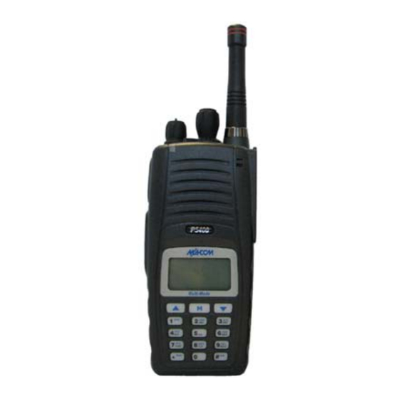
MM-012099-001 USER INTERFACE This section describes the primary user interface; the buttons, knob controls, indicators, and display. Figure 7-1: P5400 Portable Radio... -
Page 25: Controls
MM-012099-001 CONTROLS 7.1.1 Buttons and Knobs The P5400 portable radios feature two rotary control knobs, an emergency button, and a dual-position A/B switch located on the top of the radio (Figure 7-2). The Push-To-Talk (PTT) button and two option buttons are located on the side (Figure 7-3). Figure 7-2: Top View Figure 7-3: Side View... - Page 26 MM-012099-001 The functions of the button and knob controls vary depending on the mode of operation. The primary functions of the button and knob controls when in the EDACS mode of operation are listed in the following paragraphs. The functions while in other modes are discussed in later sections. POWER ON-OFF/VOLUME Applies power to the radio and adjusts audio volume.
-
Page 27: Keypad
MM-012099-001 7.1.2 Keypad The front mounted keypad of the P5450 “Scan” model has six buttons and P5470 “System” model has 15 buttons. Refer to Figure 7-4: P5450 “Scan” Radio Front Panel and Figure 7-5: P5470 “System” Model Front Panel, respectively. Figure 7-4: P5450 “Scan”... -
Page 28: Table 7-1: P5400 Front Keypad Functions
MM-012099-001 Alpha-numeric character entry is the secondary function of most of the P5400 keypad keys in the EDACS mode of operation. In addition, the (*) and (#) keys are also available. The primary and secondary functions of each key, where applicable, are described in Table 7-1 and the following section. Table 7-1: P5400 Front Keypad Functions FUNCTION Primary Function: Accesses the pre-stored menu. -
Page 29: Display
MM-012099-001 7.1.3 Display The P5400 display is made up of 3 lines. Lines 1 and 2 contain twelve alpha-numeric character blocks each. The 3 line also contains twelve blocks, each used to display radio status icons. If programmed, the display backlighting will illuminate upon power up or when radio controls are operated. Specific display characteristics will be discussed in following sub-sections. -
Page 30: Figure 7-7: Full Cycle Battery Charge Indicator
MM-012099-001 STATUS ICON DESCRIPTIONS EDACS, CONVENTIONAL, AND P25 ICONS Steady – group or channel in scan list. Appears in the 10th position of the display. Steady – priority 2 group or channel. Appears in the 10th position of the display. Steady –... -
Page 31: Tri-Color Led
MM-012099-001 Figure 7-8: Tri-Color LED 7.1.4 Tri-Color LED The Tri-Color LED changes color to indicate radio status and is visible from both the front and top of the radio (see Figure 7-2). In addition, the mode of operation may also help determine what the color of the LED represents. -
Page 32: Edacs Operation
MM-012099-001 EDACS OPERATION... -
Page 33: Edacs Operation
MM-012099-001 EDACS OPERATION TURNING ON THE RADIO 1. Power ON the radio by rotating the POWER ON-OFF/VOLUME knob clockwise. A short alert signal (if enabled through programming) indicates the radio is ready to use. 2. The display shows the last selected system and group or a default system and group (depending on programming). -
Page 34: Keypad
MM-012099-001 EMERGENCY/ Automatically selects the pre-programmed Group/System by pressing and holding HOME BUTTON for a programmed duration. It can also be used to declare an emergency by pressing and holding for a programmed duration. The button must be pre- programmed for either operation, but not both. PTT BUTTON Push-To-Talk must be pressed before voice transmission begins. -
Page 35: Figure 8-2: P5470 "System" Radio Front Panel
MM-012099-001 Figure 8-2: P5470 “System” Radio Front Panel FUNCTION Primary Function: Accesses the pre-stored menu. Secondary Function: Activates a selected item within the menu. This is similar to an “Enter” key. Primary Function: Allows the user to scroll through available systems, groups, or channels, depending on personality programming. -
Page 36: Display
MM-012099-001 DISPLAY The radio Display is made up of 3 lines (see Figure 8-3). Lines 1 and 2 contain eight alphanumeric character blocks and are used primarily to display system and group names. Line 1 also displays radio status messages. The 3rd line is used primarily to display radio status icons. All three lines are used to display menu options when in the menu mode. -
Page 37: Radio Status Icons
MM-012099-001 RADIO STATUS ICONS Status Icons indicate the various operating characteristics of the radio. The icons show operating modes and conditions and appear on the third line of the display (see Table 8-2). Table 8-2: Display Descriptions Steady – “Busy” transmitting or receiving. Appears in the 2 position of the display. -
Page 38: Tri-Color Led
MM-012099-001 Figure 8-4: Full Cycle Battery Charge Indicator The battery charge indicators illustrate approximate level only, based on battery voltage. Refer to Figure 8-4. TRI-COLOR LED Figure 8-5: Tri-Color LED The Tri-Color LED changes color to indicate radio status and is visible from both the front and top of the radio (see Figure 8-5). -
Page 39: Error Messages
MM-012099-001 MESSAGE NAME DESCRIPTION system and/or talkgroup. CC SCAN Control Indicates the control channel is lost and the radio has entered the Control Channel Scan Channel Scan mode to search for the control channel (usually out of range indication). WA SCAN Wide Area Indicates the radio has entered the Wide Area Scan mode to search for a Scan... -
Page 40: Alert Tones
MM-012099-001 ALERT TONES The P5400 radio provides audible Alert Tones or “beeps” to indicate the various operating conditions (see Table 8-3). Table 8-3: Alert Tones NAME TONE DESCRIPTION Call Originate one short mid-pitched OK to talk after pressing the push-to-talk button Call Queued one high-pitched... -
Page 41: Group/Channel Selection
MM-012099-001 Example: System: 1 = North Group: 1 = Group 1 2 = South 2 = Group 2 3 = East 3 = Group 3 4 = West 4 = Group 4 1. Press . (South is the currently selected system.) 2. -
Page 42: Backlight On/Off
MM-012099-001 5. Press twice to add as a Priority 2 group. 6. Press three times to add as a Priority 1 group. 7. Press to re-start scanning. 8.12 BACKLIGHT ON/OFF 1. Press to access the menu. 2. Press to scroll through menu until “BCKLGHT” appears. 3. -
Page 43: Using The Menu Button
MM-012099-001 8.16.1 Using the Menu Button 1. Press 2. Using the keys, scroll until the cursor (>) appears to the left of “TX POWER” in the display. 3. Press again to toggle between High and Low power. 4. “POWER = HIGH” or “POWER = LOW” will appear momentarily on the top line of the display. 8.16.2 Using the Pre-Programmed Option Button Press the Option button. -
Page 44: Figure 8-7: Backlight Menu Item Selection Parameter
MM-012099-001 Figure 8-7: Backlight Menu Item Selection Parameter 3. Press The backlight menu item is activated. Line one shows the active menu item and its current parameter setting. Line two shows the currently selected system or group name (see Figure 8-8). - Page 45 MM-012099-001 PARAMETER FEATURE DISPLAY COMMENT SETTING Display Current Home HOME Selects Home Group/Channel Group/Channel Select Desired System SYS SEL Selects a new system. Add Group/Channel to SCAN ADD Adds to Scan List. Scan List Delete Group/Channel SCAN DEL Deletes Group or Channel from Scan List. Add/Delete Scan List SCAN A/D Add or Delete from Scan List.
-
Page 46: Digital Voice Operation
MM-012099-001 Table 8-5: Information Display RADIO ID LID in EDACS/EA In CONV it has XXXXXXXX no meaning. RAM SIZ RAM Size FLSH SIZ Flash Size RF BAND Frequency Band PERS VER Software Version DSP DATE Date DSP code was built. DSP TIME Time DSP code was built. -
Page 47: Private Mode
MM-012099-001 call or hang time is still active. Individual phone, all call, and emergency calls are transmitted clear if the digital mode is disabled or inoperative. If receiving an analog message trunked call, the radio responds in the analog mode during the hang time on the working channel. -
Page 48: Private Operation
MM-012099-001 Figure 8-10: Group/Channel Encryption Key Display 8.18.3.2 Key Zero All cryptographic keys can be zeroed (erased from radio memory) by pressing the button and while still pressing this button, press and hold the OPTION button. Press both buttons for 2 seconds. A series of beeps will begin at the start of the 2 second period and then switch to a solid tone after the keys have been KEY ZERO zeroed. -
Page 49: Scanning Trunked Groups
MM-012099-001 group. If a group is entered in the scan list more than once, and in different modes (clear, digital, or private), only the first occurrence of the group will be used. Table 8-6: Transmit/Receive Mode Compatibility for Digital Voice Operation GROUP/CHANNEL CLEAR DIGITAL... - Page 50 MM-012099-001 4. Press the key a second time to set the group to Priority 2. A is displayed on line three. 5. Press a third time to set the group to Priority 1. A is displayed on line three. The priority level section sequence only advances the group to the next high priority level and stops at priority level 1.
-
Page 51: Deleting Groups From A Scan List
MM-012099-001 To quickly view multiple group scan status, press either or the key. Then slowly but consistently rotate the group knob. Each group status will appear on the display. 8.19.3 Deleting Groups from a Scan List P5450 Model Radio 1. With scan operation turned OFF, select the desired group to delete from the selected trunked system group scan list. -
Page 52: Wide Area System Scanning
8.20.1 Wide Area System Scanning The P5400 series radio can be programmed for Wide Area System Scan operation for roaming across mobile systems. Upon the loss of the currently selected system's control channel, radios can be programmed to automatically scan the control channels of other systems. If a new control channel is found, the radio will switch to the new system and sound an alert tone. -
Page 53: Receiving An Emergency Call
MM-012099-001 8.21.1 Receiving an Emergency Call When receiving an Emergency Call on the selected group and system, an alert beep is heard and *RXEMER* displayed. The message flashes in the display on line two until the emergency condition is cleared. 8.21.2 Declaring an Emergency Call Perform the following steps to send an emergency call to a selected system and group (or on an optionally... -
Page 54: Sending An Individual Call
MM-012099-001 Figure 8-11: Calls Received Lists To access the Calls Received List, press the key twice. Use the buttons to scroll through the list. Pressing the key will display the time elapsed since the call was received. After pressing the display will appear similar to Figure 8-12. Figure 8-12: WHC Individual Call Display Pressing the PTT will initiate an individual call to the displayed logical ID. -
Page 55: Call Storage Lists
Call Storage Lists There are two lists available for call storage in the P5400 series radios, the calls received list (1 - 10) and the personality list (1 - 99 as defined by the user). When the individual call mode is entered by pressing , the calls received list is available. -
Page 56: Sending A Telephone Interconnect Call
MM-012099-001 8.23.2 Sending a Telephone Interconnect Call 8.23.2.1 Pre-Stored Number Use the following procedures to initiate and complete a Telephone Interconnect call. 1. P5470 Model: To select a previously stored phone number, press the key. Use the buttons to scroll through the list of stored numbers. P5450 Model: To select a previously stored phone number, press the key. - Page 57 MM-012099-001 Overdial operation can also be used to initiate a telephone interconnect call via DTMF signaling if a dial tone has already been accessed on the system. This method makes a telephone interconnect call while operating in the conventional mode but will also function in trunked mode if a dial tone is directly accessible.
-
Page 58: Programmable Entries
MM-012099-001 METHOD 2: (P5470 model radios only) 1. Enter the overdial selection mode by pressing the button. 2. Press and hold the PTT button while entering the overdial number sequence from the keypad. This method sends DTMF tones during individual, telephone interconnect, trunked group, or conventional channel calls. -
Page 59: Status Operation
MM-012099-001 8.25.1 Status Operation P5470 Model Radio One of two methods can be used to transmit a status condition. METHOD 1: 1. Press the key, then use the buttons to scroll to the pre-programmed status condition. STATUS and 0 through 9 pre-programmed status selections are available from the menu. -
Page 60: Emergency Operation
8.28 PORTABLE DATA The P5400 series portable radios, when operating in the EDACS Trunked configuration, permit both voice and data calls to be transmitted and received. The radio can handle only one type of call at a time; however, either data or voice is selected transparently by the operator through normal usage of the radio. -
Page 61: Data Off Operation
MM-012099-001 DATA ON Appears for two seconds on top line of display when the radio is toggled to the data enabled state. 8.28.2 DATA OFF Operation The radio can be placed in the data disabled state by any of the following methods. When the data state is DATA OFF disabled, appears on the top line of the display. -
Page 62: Data Lockout Mode
MM-012099-001 • Receive an Agency, Fleet, or System All Call. • Press (P5450 model) or (P5470 model) to toggle Scan ON or OFF. 8.28.6 Data Lockout Mode During the voice call scan hang time (pre-programmed) the radio will not receive data calls. - Page 63 MM-012099-001 This page intentionally left blank...
-
Page 64: Conventional Operation
MM-012099-001 CONVENTIONAL OPERATION... -
Page 65: Controls
MM-012099-001 CONVENTIONAL OPERATION The radio functions in the conventional mode when using conventional communications channels (non- trunked). CONTROLS The radio features two rotary control knobs and an emergency button mounted on the top of the radio. Push-To-Talk and option buttons are mounted on the side. The front mounted keypad has six buttons on the P5450 Scan model and 15 buttons on the P5470 System model. -
Page 66: Keypad
MM-012099-001 9.1.2 Keypad The keys on the keypad have special functions and are labeled using a symbol or abbreviated word describing its primary function. Numeric entry is a secondary function of the keys. Each key is described in the following subsections. Figure 9-1: P5450 “Scan”... -
Page 67: Figure 9-2: P5470 "System" Radio Front Panel
MM-012099-001 Figure 9-2: P5470 “System” Radio Front Panel FUNCTION Primary Function: Allows the user to scroll through available systems, groups, or channels, depending on personality programming. Secondary Function: Changes the selection for an item within a list. Primary Function: Accesses the pre-stored menu. Secondary Function: Activates a selected item within a list. -
Page 68: Display
MM-012099-001 DISPLAY The radio display is made up of 3 lines (see Figure 9-3). Lines 1 and 2 contain eight alphanumeric character blocks and are used primarily to display system and group names. Line 1 also displays radio status messages. The 3rd line is used primarily to display radio status icons. All three lines are used to display menu options when in the menu mode. -
Page 69: Tri-Color Led
MM-012099-001 Steady – group or channel in scan list. Appears in the 10th position of the display. Steady – priority 2 group or channel. Appears in the 10th position of the display. Steady – priority 1 group or channel. Appears in the 10th position of the display. Steady (rotates clockwise) –... -
Page 70: Status Messages
MM-012099-001 STATUS MESSAGES During radio operation, various radio Status Messages can be displayed. The messages are described below. MESSAGE NAME DESCRIPTION TALKARND Talkaround Indicates the radio is operating on conventional channels in talkaround mode (no repeater). LOW BATT Battery voltage has dropped to the point to where the radio is no longer Battery able to transmit. -
Page 71: System Selection
MM-012099-001 3. Adjust the POWER ON-OFF/VOLUME knob to the desired volume level. 4. Select the desired system and group. The display indicates the current system and group names. 5. The radio is now ready to transmit and receive calls. SYSTEM SELECTION METHOD 1: From control... -
Page 72: Modify Scan List
MM-012099-001 (P5470 model radios only) Direct Access: Press to enter the group select mode. METHOD 3: . The radio will move to Press the numeric key mapped to the desired group. Press the selected group. MODIFY SCAN LIST 9.9.1 P5470 Model 1. -
Page 73: Contrast Adjust
MM-012099-001 9.12 CONTRAST ADJUST 1. Press to access the menu. 2. Press to scroll through menu until “CONTRAST” appears. 3. Press to select Contrast menu. 4. Press to adjust contrast setting from 1 - 4. 5. Press to select new contrast setting. 9.13 DECLARING AN EMERGENCY 1. -
Page 74: Menu
MM-012099-001 9.16 MENU The Menu function accesses features that are not available directly from the keypad. The order and actual menu items available is configurable through programming. At radio power up, the menu item that is at the top of the menu list will always be displayed first. Subsequent access to the menu function will return the last menu item that was shown in the display and cursor position. - Page 75 MM-012099-001 3. Press The backlight menu item is activated. Line one shows the active menu item and its current parameter setting. Line two shows the currently selected system or group name (see Figure 9-8). Figure 9-8: Backlight Menu Display 4. The menu item's parameter setting shown in the display can now be changed by using 5.
-
Page 76: Table 9-3: Menu Item Information
MM-012099-001 Table 9-3: Menu Item Information PARAMETER FEATURE DISPLAY COMMENT SETTING Keypad Lock Menu Item: Locked Locks the keypad. To unlock; press and release then within KEY LOCK 1 second press the option button (NOTE: this sequence is also a Unlocked short cut to locking the keypad.) Once Selected:... -
Page 77: Digital Voice Operation
MM-012099-001 Table 9-4: Information Display RADIO ID LID in EDACS/EA. In CONV it has XXXXXXXX no meaning. RAM SIZ RAM Size FLSH SIZ Flash Size RF BAND Frequency Band PERS VER Software Version DSP DATE Date DSP code was built. DSP TIME Time DSP code was built. -
Page 78: Receiving A Call
MM-012099-001 Individual phone, all call, and emergency calls are transmitted clear if the digital mode is disabled or inoperative. If receiving an analog I-Call, the radio responds in the analog mode during the hang time. *WHC* When using the feature to respond to an I-Call (after the hang time has expired), the call is transmitted in the mode defined by the system mode as programmed for the current system if the ID being called is not in the I-Call list. - Page 79 MM-012099-001 This page intentionally left blank...
- Page 80 MM-012099-001 P25 OPERATION...
-
Page 81: P25 Operation
MM-012099-001 10 P25 OPERATION Once a P25 system has been selected from the available systems on your P5400 series portable radio, the characteristics described in the following sections will govern operation. 10.1 TURNING ON THE RADIO 1. Power ON the radio by rotating the POWER ON-OFF/VOLUME knob clockwise. A short alert signal (if enabled through programming) indicates the radio is ready to use. -
Page 82: Keypad
MM-012099-001 PTT BUTTON Push-To-Talk must be pressed before voice transmission begins. In trunked mode the radio’s ID is transmitted upon depression of the PTT button. SIDE OPTION Exits the current operation (removing all displays associated with it) and returns BUTTON 1 the radio to the selected talk group. - Page 83 MM-012099-001 Figure 10-2: P5470 “System” Radio Front Panel FUNCTION Primary Function: Accesses the pre-stored menu. Secondary Function: Activates a selected item within the menu. This is similar to an “Enter” key. Primary Function: Allows the user to scroll through available systems, groups, or channels, depending on personality programming.
-
Page 84: Display
MM-012099-001 10.3 DISPLAY The radio Display is made up of 3 lines (see Figure 10-3). Lines 1 and 2 contain eight alphanumeric character blocks and are used primarily to display system and group names. Line 1 also displays radio status messages. The 3rd line is used primarily to display radio status icons. All three lines are used to display menu options when in the menu mode. -
Page 85: Radio Status Icons
MM-012099-001 10.4 RADIO STATUS ICONS Status Icons indicate the various operating characteristics of the radio. The icons show operating modes and conditions and appear on the third line of the display (see Table 10-2). Table 10-2: Display Descriptions Steady – “Busy” transmitting or receiving. Appears in the 2 position of the display. -
Page 86: Tri-Color Led
MM-012099-001 Figure 10-4: Full Cycle Battery Charge Indicator The battery charge indicators illustrate approximate level only, based on battery voltage. Refer to Figure 10-4. 10.5 TRI-COLOR LED Figure 10-5: Tri-Color LED The Tri-Color LED changes color to indicate radio status and is visible from both the front and top of the radio (see Figure 10-5). -
Page 87: Error Messages
MM-012099-001 MESSAGE NAME DESCRIPTION system and/or talkgroup. CC SCAN Control Indicates the control channel is lost and the radio has entered the Control Channel Scan Channel Scan mode to search for the control channel (usually out of range indication). WA SCAN Wide Area Indicates the radio has entered the Wide Area Scan mode to search for a Scan new system (if enabled through programming). -
Page 88: Alert Tones
MM-012099-001 10.7 ALERT TONES The P5400 radio provides audible Alert Tones or “beeps” to indicate the various operating conditions (see Table 10-3). Table 10-3: Alert Tones NAME TONE DESCRIPTION Call Originate one short mid-pitched OK to talk after pressing the push-to-talk button Call Queued one high-pitched... -
Page 89: Group/Channel Selection
MM-012099-001 Example: System: 1 = North Group: 1 = Group 1 2 = South 2 = Group 2 3 = East 3 = Group 3 4 = West 4 = Group 4 1. Press . (South is the currently selected system.) 2. -
Page 90: Backlight On/Off
MM-012099-001 5. Press twice to add as a Priority 2 group. 6. Press three times to add as a Priority 1 group. 7. Press to re-start scanning. 10.11 BACKLIGHT ON/OFF 1. Press to access the menu. 2. Press to scroll through menu until “BCKLGHT” appears. 3. -
Page 91: Using The Menu Button
MM-012099-001 10.15.1 Using the Menu Button 5. Press 6. Using the keys, scroll until the cursor (>) appears to the left of “TX POWER” in the display. 7. Press again to toggle between High and Low power. 8. “POWER = HIGH” or “POWER = LOW” will appear momentarily on the top line of the display. 10.15.2 Using the Pre-Programmed Option Button Press the Option button. -
Page 92: Table 10-4: Menu Item Information
MM-012099-001 Figure 10-7: Backlight Menu Item Selection Parameter 3. Press The backlight menu item is activated. Line one shows the active menu item and its current parameter setting. Line two shows the currently selected system or group name (see Figure 10-8). - Page 93 MM-012099-001 PARAMETER FEATURE DISPLAY COMMENT SETTING Display Current DISP KEY Displays current encryption key. Informational display Encryption Key only. No selectable settings. Display Current Home HOME Selects Home Group/Channel Group/Channel Select Desired System SYS SEL Selects a new system. Add Group/Channel to SCAN ADD Adds to Scan List.
-
Page 94: Digital Voice Operation
MM-012099-001 Table 10-5: Information Display RADIO ID LID in EDACS/EA In CONV it has XXXXXXXX no meaning. RAM SIZ RAM Size FLSH SIZ Flash Size RF BAND Frequency Band PERS VER Software Version DSP DATE Date DSP code was built. DSP TIME Time DSP code was built. -
Page 95: Private Mode
MM-012099-001 call or hang time is still active. Individual phone, all call, and emergency calls are transmitted clear if the digital mode is disabled or inoperative. If receiving an analog message trunked call, the radio responds in the analog mode during the hang time on the working channel. -
Page 96: Private Operation
MM-012099-001 Figure 10-10: Group/Channel Encryption Key Display 10.17.3.2 Key Zero All cryptographic keys can be zeroed (erased from radio memory) by pressing the button and while still pressing this button, press and hold the OPTION button. Press both buttons for 2 seconds. A series of beeps will begin at the start of the 2 second period and then switch to a solid tone after the keys have been KEY ZERO zeroed. -
Page 97: Scanning Trunked Groups
MM-012099-001 group. If a group is entered in the scan list more than once, and in different modes (clear, digital, or private), only the first occurrence of the group will be used. Table 10-6: Transmit/Receive Mode Compatibility for Digital Voice Operation GROUP/CHANNEL CLEAR DIGITAL... - Page 98 MM-012099-001 4. Press the key a second time to set the group to Priority 2. A is displayed on line three. 5. Press a third time to set the group to Priority 1. A is displayed on line three. The priority level section sequence only advances the group to the next high priority level and stops at priority level 1.
-
Page 99: Deleting Groups From A Scan List
MM-012099-001 To quickly view multiple group scan status, press either or the key. Then slowly but consistently rotate the group knob. Each group status will appear on the display. 10.18.3 Deleting Groups from a Scan List P5450 Model Radio 1. With scan operation turned OFF, select the desired group to delete from the selected trunked system group scan list. -
Page 100: Wide Area System Scanning
MM-012099-001 10.19.1 Wide Area System Scanning The P5400 series radio can be programmed for Wide Area System Scan operation for roaming across mobile systems. Upon the loss of the currently selected system's control channel, radios can be programmed to automatically scan the control channels of other systems. If a new control channel is found, the radio will switch to the new system and sound an alert tone. -
Page 101: Receiving An Emergency Call
MM-012099-001 10.20.1 Receiving an Emergency Call When receiving an Emergency Call on the selected group and system, an alert beep is heard and *RXEMER* displayed. The message flashes in the display on line two until the emergency condition is cleared. 10.20.2 Declaring an Emergency Call Perform the following steps to send an emergency call to a selected system and group (or on an optionally pre-programmed group). -
Page 102: Sending An Individual Call
MM-012099-001 Figure 10-11: Calls Received Lists To access the Calls Received List, press the key twice. Use the buttons to scroll through the list. Pressing the key will display the time elapsed since the call was received. After pressing the display will appear similar to Figure 10-12. Figure 10-12: WHC Individual Call Display Pressing the PTT will initiate an individual call to the displayed logical ID. -
Page 103: Call Storage Lists
10.21.3 Call Storage Lists There are two lists available for call storage in the P5400 series radios, the calls received list (1 - 10) and the personality list (1 - 99 as defined by the user). When the individual call mode is entered by pressing , the calls received list is available. -
Page 104: Sending A Telephone Interconnect Call
MM-012099-001 10.22.2 Sending a Telephone Interconnect Call 10.22.2.1 Pre-Stored Number Use the following procedures to initiate and complete a Telephone Interconnect call. 1. P5470 Model: To select a previously stored phone number, press the key. Use the buttons to scroll through the list of stored numbers. P5450 Model: To select a previously stored phone number, press the key. - Page 105 MM-012099-001 Overdial operation can also be used to initiate a telephone interconnect call via DTMF signaling if a dial tone has already been accessed on the system. This method makes a telephone interconnect call while operating in the conventional mode but will also function in trunked mode if a dial tone is directly accessible.
-
Page 106: Programmable Entries
MM-012099-001 METHOD 2: (P5470 model radios only) 1. Enter the overdial selection mode by pressing the button. 2. Press and hold the PTT button while entering the overdial number sequence from the keypad. This method sends DTMF tones during individual, telephone interconnect, trunked group, or conventional channel calls. -
Page 107: Status Operation
MM-012099-001 10.24.1 Status Operation P5470 Model Radio One of two methods can be used to transmit a status condition. METHOD 1: 1. Press the key, then use the buttons to scroll to the pre-programmed status condition. STATUS and 0 through 9 pre-programmed status selections are available from the menu. -
Page 108: Emergency Operation
10.27 PORTABLE DATA The P5400 series portable radios, when operating in the EDACS Trunked configuration, permit both voice and data calls to be transmitted and received. The radio can handle only one type of call at a time; however, either data or voice is selected transparently by the operator through normal usage of the radio. -
Page 109: Data Off Operation
MM-012099-001 DATA ON Appears for two seconds on top line of display when the radio is toggled to the data enabled state. 10.27.2 DATA OFF Operation The radio can be placed in the data disabled state by any of the following methods. When the data state is DATA OFF disabled, appears on the top line of the display. -
Page 110: Data Lockout Mode
MM-012099-001 • Receive an Agency, Fleet, or System All Call. • Press (P5450 model) or (P5470 model) to toggle Scan ON or OFF. 10.27.6 Data Lockout Mode During the voice call scan hang time (pre-programmed) the radio will not receive data calls. 10.28 GROUP CALLS IN P25 MODE 10.28.1 Transmitting a Group Call 1. -
Page 111: Emergency Group Calls In P25 Mode
MM-012099-001 3. When the radio receives a P25 call, the radio will unmute and the ID of the transmitting radio will appear in the display. 4. Press the PTT button to respond. 5. Unanswered calls will appear in the Who Has Called (WHC) list. 10.30 EMERGENCY GROUP CALLS IN P25 MODE There is no method available for a system-wide Emergency clear. -
Page 112: Warranty Information
MM-012099-001 TECHNICAL ASSISTANCE WARRANTY INFORMATION... -
Page 113: Technical Assistance
MM-012099-001 11 TECHNICAL ASSISTANCE The Technical Assistance Center's (TAC) resources are available to help with overall system operation, maintenance, upgrades and product support. TAC is the point of contact when answers are needed to technical questions. Product specialists, with detailed knowledge of product operation, maintenance and repair provide technical support via a toll-free (in North American) telephone number. -
Page 114: Basic Troubleshooting
MM-012099-001 12 BASIC TROUBLESHOOTING Use Table 12-1 as a troubleshooting guide if the radio is not functioning properly. If additional assistance is required, contact a qualified service technician or call M/A-COM at 1-800-528-7711. Table 12-1: Troubleshooting SYMPTOM POSSIBLE CAUSE POSSIBLE SOLUTION Radio will not turn on Low battery charge Change the battery pack to a fully... - Page 115 MM-012099-001 BATTERY WARRANTY A. M/A-COM, Inc. (hereinafter "Seller") warrants to the original purchaser for use (hereinafter "Buyer") that nickel-cadmium and nickel-metal hydride batteries supplied by Seller shall be free from defects in material and workmanship, and shall conform to its published specifications for a period of twelve (12) months from the date of purchase.
- Page 116 MM-012099-001 WARRANTY A. M/A-COM, Inc. (hereinafter "Seller") warrants to the original purchaser for use (hereinafter "Buyer") that Equipment manufactured by or for the Seller shall be free from defects in material and workmanship, and shall conform to its published specifications. With respect to all non-M/A-COM Equipment, Seller gives no warranty, and only the warranty, if any, given by the manufacturer shall apply.
- Page 117 Tyco Electronics Wireless Systems Segment 221 Jefferson Ridge Parkway Lynchburg, Virginia 24501 (Outside USA, 1-434-385-2400) Toll Free 1-800-528-7711 www.macom-wireless.com Printed in U.S.A.
- Page 118 Rev. p1, Jul/07 This booklet contains important safety information regarding specific absorption rate (SAR) and RF exposure limits included in United States and international standards. Read the information in this booklet before operating your radio. M/A-COM P5400 Series Portable Radios...
- Page 119 MANUAL REVISION HISTORY DATE DESCRIPTION Jul/07 Initial release ACKNOWLEDGEMENTS The software contained in this device is copyrighted by M/A-COM, Inc. Unpublished rights are reserved under the copyright laws of the United States. This device is made under license under one or more of the following U.S. Patents: 4,590,473;...
-
Page 120: Safety Symbol Conventions
TABLE OF CONTENTS Page SAFETY SYMBOL CONVENTIONS ........3 SAFETY TRAINING INFORMATION ........4 OPERATING TIPS ..............5 OPTIONS AND ACCESSORIES ..........7 BATTERIES................7 TECHNICAL ASSISTANCE ........... 7 BATTERY WARRANTY............10 WARRANTY ................11 SAFETY SYMBOL CONVENTIONS The following conventions are used to alert the user to general safety precautions that must be observed during all phases of operation, service, and repair of this product. -
Page 121: Safety Training Information
SAFETY TRAINING INFORMATION The M/A-COM P5400 portable radio generates RF electromagnetic energy during transmit mode. This radio is designed for and classified as “Occupational Use Only,” meaning it must be used only during the course of employment by individuals aware of the hazards and the ways to minimize such hazards. -
Page 122: Operating Tips
transmission, M/A-COM recommends you hold the microphone at least 5 cm (2 inches) from your mouth, and slightly off to one side. Table 1-1: RF Exposure Compliance Testing Distances RADIO FREQUENCY TESTED DISTANCES (worst case scenario) Body Face 378-430 MHz 1.1 cm 2.5 cm The information in this section provides the information needed to make the user aware... - Page 123 3.1.1 Antenna Care and Replacement Always keep the antenna at least 0.43 inches (1.1 cm.) away from the body and 1.0 inch (2.5 cm.) from the face when transmitting to ensure FCC RF exposure compliance requirements are not exceeded. Do not use the portable radio with a damaged or missing antenna. A minor burn may result if skin comes into contact with a damaged antenna.
-
Page 124: Options And Accessories
BATTERIES The P5400 series portable radios use rechargeable, recyclable Nickel Cadmium (NiCd), Nickel Metal Hydride (NiMH), or Lithium Ion (Li Ion) batteries. Please follow the directions below to maximize the useful life of each type of battery. - Page 125 If the battery is ruptured or is leaking electrolyte that results in skin or eye contact with the electrolyte, immediately flush the affected area with water. If the battery electrolyte gets in the eyes, flush with water for 15 minutes and consult a physician immediately.
-
Page 126: Technical Assistance
BATTERY DISPOSAL In no instance should a battery be incinerated. Disposing of a battery by burning will cause an explosion. CAUTION RECHARGEABLE BATTERY PACK DISPOSAL – The product you have purchased contains a rechargeable battery. The battery is recyclable. At the end of its useful life, under various state and local laws, it may be illegal to dispose of this battery into the municipal waste stream. -
Page 127: Battery Warranty
BATTERY WARRANTY M/A-COM, Inc. (hereinafter "Seller") warrants to the original purchaser for use (hereinafter "Buyer") that nickel-cadmium and nickel-metal hydride batteries supplied by Seller shall be free from defects in material and workmanship, and shall conform to its published specifications for a period of twelve (12) months from the date of purchase. -
Page 128: Warranty
WARRANTY M/A-COM, Inc. (hereinafter "Seller") warrants to the original purchaser for use (hereinafter "Buyer") that Equipment manufactured by or for the Seller shall be free from defects in material and workmanship, and shall conform to its published specifications. With respect to all non-M/A-COM Equipment, Seller gives no warranty, and only the warranty, if any, given by the manufacturer shall apply. - Page 129 Tyco Electronics Wireless Systems Segment 221 Jefferson Ridge Parkway Lynchburg, Virginia 24501 (Outside USA, 1-434-385-2400) Toll Free 1-800-528-7711 www.macom-wireless.com Printed in U.S.A.
Need help?
Do you have a question about the P5400 series and is the answer not in the manual?
Questions and answers